Installation Guide
Connect 2.0 Shelter, wiring guide for 12ft solar powered unit
www.landscapeforms.com Ph: 800.521.2546
Date: February 21, 2019
Page 1 of 5
1. Anchorkitinstallation
2. Frameassembly
3. Roofassembly
4. Wallglassassembly
5. Wiringconnections
Orderofoperations:
ToolsRequired
•wiringtools
•3/32”hexkey
•3/16”hexkey
•5/16”Socketwrench
•Flatheadscrewdriveror¼”socketwrench
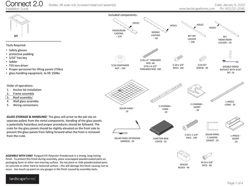
Includedcomponents:
•Uplights,withwiringharnesses,pre‐installedinfronthorizontalbeam
•Downlights,withwiringharnessandconnectors,oneperrafter
•Wayfindinglights,withwiringharness,twoperunit
•Glasssolarpanelwithbracketsandattachinghardware
•16batterieswithwiringharness
INSTALLATION:
Orderofinstallation:Installbatteriesinfronthorizontalbeam.BatteriesareinstalledinaVelcroharness
tofacilitateeasierremoval,ifneeded.Installdownlights.Installwayfindinglights.Connectwiring
harnessestodriver.Installfuse.Runtestoflights.
1. Removeaccesscoverinhorizontalbeamnearfrontrightpost.EnsureVelcrostripisinstalledon
fronthorizontalbeam.SecureoneendoflongVelcroharnesstothetophalfofthestripmountedin
thehorizontalbeam.Connect(‐)leadofthebatteryharnesstothefirstbattery(‐).Installshort
jumperharnesstothepositivepoleofthebatteryasshowninFig.2.Attachtheotherendofthe
jumperharnesstothesecondbattery.Installthesecondbattery.Repeatthisprocessforbatteries3
and4,withthe4th batteryhookinguptothemainwireharness(+)connector.Repeatthisprocess
fortheremainingbatteries.SeeFig.4forwiringreference.SlideeachbatteryintoVelcroharnessas
itisbeinginstalled.Onceallbatteriesareinstalled,twistVelcrostrapandsecureittothebottomof
thematingVelcrostripinthehorizontalbeam,seeFig.3.
2. Firstrafterdownlight:makeconnectionatfronthorizontaltoquickdisconnect.Pushrafterlight
connectionthroughgrommet.Grommetsmayberemovedtopushwiresthroughandthen
reinstalled,ifnecessary.SeeFig.5.Usinga3/32”hexkey,attachdownlighttorafterusing(6)#8‐32
x5/16socketbuttonheadcapscrews,locatedinhardwarepack#62599.Donotovertightenscrews.
3. Installremainingrafterdownlights:makeconnectiontoquickdisconnects.Pushconnectionthrough
grommetonfronthorizontalbeam.Attachdownlighttorafter,seeFig.5.
4. Unusedgrommetsonrearhorizontalbeamcanbesealedwithclearorblacksilicone(suppliedby
others).
5. Installleftandrightsiderafterskins,withthesharperangleoftheskintowardthefrontofthe
rafter.SeeFig.6.Rafterskinshaveabossonthebottomflangethathooksintothedownlight,see
Fig.6.Hookthebottomoftheskinintopositionandthenrotatethetopofskinuptotherafter
beam.Usinga3/16”hexkey,install(2)¼‐20x¾”socketheadcapscrews,locatedinhardwarepack
#62599.Tightenuntilgapbetweenlightandrafterskinisgoneandrafterskindoesnotrattle.Do
notovertightenscrews.
6. Wayfindinglights:Runwiringharnessupthroughfrontverticalpost.Onthefrontleftsideofthe
unit,removetheaccesscoveronthefronthorizontalbeam.Makeconnectionfromthewiring
harnesstothequickdisconnectlocatedinthebeam.SecureLEDtofrontverticalpost,using(4)8‐32
x½”hexheadmachinescrewswithexternaltoothlockwasher,locatedinhardwarepack#62810,
seeFig.7.Beforefinaltighteningofscrews,ensureonlythelensfromthelightisshowingthrough
thefrontopening.Repeatforoppositeside.Installcoverplates,using(2)¼‐20x½”socketheadcap
screws,locatedinhardwarepack#62607,seeFig.8.Makeconnectiontopre‐installedwiring
harnesslabeled“wayfindinglight”.
7. Driverplateassembly:Attachdriverplatetofronthorizontalbeam,inthefrontrightaccess
location,seeFig.9.
8. MakeconnectionstoPDMaslabeled:Uplight,Wayfinding(x2),Downlight,seeFigs10and11.Make
connectionstoMorningstarunit,intheordernotedonthedevice.Whenallofthewiring
connectionsarecomplete,installthefuse,seeFig.9.
9. FollowtheinstructionsfortheMorningstarunittotestthelights.Replaceaccesscover.
