ASSEMBLEWITHCARE! Pangard IIPolyesterPowdercoat isastrong,long‐lasting
finish.Toprotectthisfinishduringassembly,placeunwrappedpowdercoated partson
packagingfoamorothernon‐marringsurface.Donotplaceorslidepowdercoated parts
onconcreteorotherhardortexturedsurface– thiswilldamagethefinishcausingrust
tooccur.Usetouch‐uppaintonanygougesinthefinishcausedbyassemblytools.
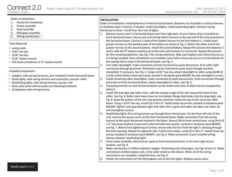
PROCEDUREFORINSTALLATION:
1. Prepareproperconcreteslabasrequired.
2. Freestandingunitshipswithglidesinstalled.Unitcanbesetinplace.
Note:DONOTDRAGunitacrossconcreteorotherroughsurfaces.Thiscoulddamagethe
finish.
ForSURFACEMOUNT:leaveglidesinstalled.
1. Turnunitupsidedownonprotectivepadding.Installsurfacemountboltsasshownin
Fig.4.
2. Setunitinposition.Tracearoundanchorstomarkholelocations.
3. Moveunit.Drillholesaccordingtoanchormanufacturer’srecommendations.Clear
holesofdebris.
4. Testfitunittomakesureholesalignwithanchorbolts.
5. Installdrop‐inanchors(orotheranchoringoption).
6. Removesurfacemountboltsfromunit.Installintodrop‐inanchors.Usethesupplied
washerasaheightgauge,seeFig.1,forthesurfacemountbolt.Thetopofthe
threadedportionofthesurfacemountboltshouldbeflushwiththetopofthe
washer.Removethewasheraftersettingtheheight,andreuseforthesecondsurface
mountbolt.
7. Setunitoversurfacemountanchors.Verifythattherubberpads(glides)aresitting
firmlyonthehardsurface.Donotallowtheweightofthebenchtositontopofthe
surfacemountboltasthiswillcausedamage.
8. Installsetscrewstosecure,seeFig.2.Gentlyliftupontheendsofthebenchtoverify
propermounting.
ForEMBEDDEDMOUNT:leaveglidesinstalled.
1. Turnunitupsidedownonprotectivepadding.
2. RemoveonescrewfromeachglidepadasshowninFig.5.
3. InstallthreadedrodsasshowninFig.6.
4. Setunitinposition.Tracearoundrodstomarkholelocations.
5. Moveunit.Drillholesaccordingtoanchormanufacturer’srecommendations,seeFig.
3.Clearholesofdebris.
6. Testfitunittomakesureholesalignandembeddedrodsarenotrestingonthe
bottomoftheholes.
7. Removeunitandfillholeswithanchoringadhesiveasrecommendedby
manufacturer.Fillholesfromthebottomuptopreventairpockets.Donotfillholes
tothetop.
8. Setunitinplace.Wipeawayexcessadhesivebeforeitcures.
9. Allowbenchtositundisturbeduntiladhesivefullycures.
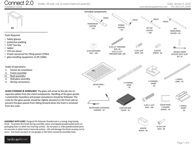
Includedcomponents:
ToolsRequiredforsurfacemountorembeddedoptions:
•Safetyglasses
•Hammerdrillwithmasonrybits
•Hexkey,1/8”(surfacemount)7/32”(embedded)
•Flatbladescrewdriver(surfacemount)
•Chemicalanchoringadhesive(HiltiHITRE500orequivalent)(embedded)
•(2)Zinc‐plateddrop‐inanchorsfor5/8‐11threadsize(surfacemount),for
usewithMagni‐coatedbolts
Installation Guide
Rest bench
www.landscapeforms.com Ph: 800.521.2546
Date: November 6, 2017
Page 1 of 2
5/8‐11threaded
Bolt
2x‐ surfacemount
1/4‐20x1‐1/2”hex
Setscrew
2x–surfacemount
3/8‐16x5‐1/8”
Threadedrod
4x– embedmount
Backedbench
Backlessbench
5/8washerforspacing
1x–surfacemount
