manuals.online logo
Brands
  1. Home
  2. •
  3. Brands
  4. •
  5. Landscape Forms
  6. •
  7. Outdoor Furnishing
  8. •
  9. Landscape Forms Typology 800.521.2546 User manual

Landscape Forms Typology 800.521.2546 User manual

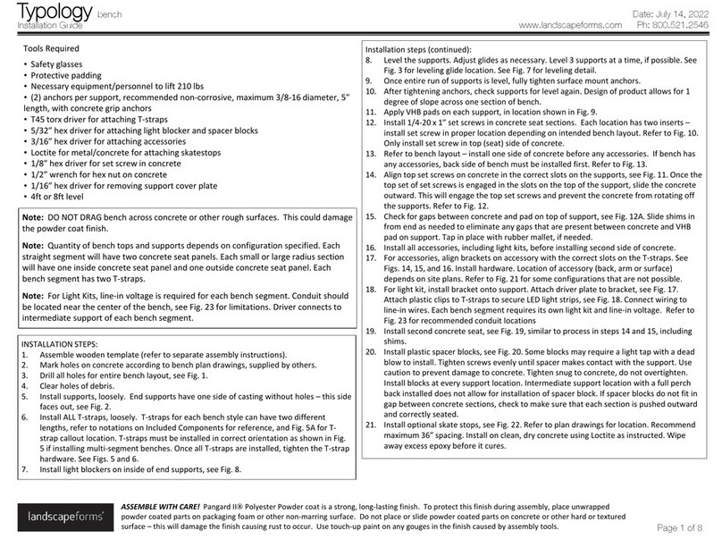
Installation steps (continued):
8. Level the supports. Adjust glides as necessary. Level 3 supports at a time, if possible. See
Fig. 3 for leveling glide location. See Fig. 7 for leveling detail.
9. Once entire run of supports is level, fully tighten surface mount anchors.
10. After tightening anchors, check supports for level again. Design of product allows for 1
degree of slope across one section of bench.
11. Apply VHB pads on each support, in location shown in Fig. 9.
12. Install 1/4-20 x 1” set screws in concrete seat sections. Each location has two inserts –
install set screw in proper location depending on intended bench layout. Refer to Fig. 10.
Set aside washers and nuts for installation in future step.
13. Refer to bench layout –install one side of concrete before any accessories. If bench has
any accessories, back side of bench must be installed first. Refer to Fig. 13.
14. Align bottom set screws on concrete in the correct slots on the supports, see Fig. 11. Lift
concrete into bottom set of slots, then rotate up and toward the center of the bench. Use
caution to prevent set screws from scraping or damaging concrete. Once the top set of
set screws is engaged in the slots on the top of the support, slide the concrete outward.
This will engage the top set screws and prevent the concrete from rotating off the
supports. Refer to Figs. 12A and 12B.
15. Install all accessories, including light kits, before installing second side of concrete.
16. For accessories, align brackets on accessory with the correct slots on the T-straps. See
Figs. 14, 15, and 16. Install hardware. Location of accessory (back, arm or surface)
depends on site plans. Refer to Fig. 23 for some configurations that are not possible.
17. For light kit, install bracket onto support. Attach driver plate to bracket, see Fig. 17.
Attach plastic clips to T-straps to secure LED light strips, see Fig. 18. Connect wiring to
line-in wires. Each bench segment requires its own light kit and line-in voltage. Refer to
Fig. 25 for recommended conduit locations
18. Install second concrete seat, see Fig. 19, similar to process in step 14.
19. Install spacer blocks, see Fig. 22. Some block may require a light tap with a dead blow to
install. Use caution to prevent damage to concrete. Tighten snug to concrete, do not
overtighten. Install blocks at every support location. Intermediate support location with a
full perch back installed does not allow for installation of spacer block. If spacer blocks do
not fit in gap between concrete sections, check to make sure that each section is pushed
outward and correctly seated.
20. Remove end cap from each support, see Fig. 20.
21. Install nut and washer (set aside in step 12) on bottom of concrete, up from bottom at
the support, see Fig. 21. The set screw located in the concrete at the top of the section
does not receive a washer/nut. Do not overtighten.
22. Tighten washer and nut on concrete, do not overtighten. Reinstall support end caps.
23. Install optional skatestops, see Fig. 24. Refer to plan drawings for location. Recommend
maximum 36” spacing. Install on clean, dry concrete using Loctite as instructed. Wipe
away excess epoxy before it cures.
Installation Guide
Typology bench
www.landscapeforms.com Ph: 800.521.2546
ASSEMBLE WITH CARE! Pangard IIPolyester Powder coat is a strong, long-lasting finish. To protect this finish during assembly, place unwrapped
powder coated parts on packaging foam or other non-marring surface. Do not place or slide powder coated parts on concrete or other hard or textured
surface –this will damage the finish causing rust to occur. Use touch-up paint on any gouges in the finish caused by assembly tools.
Note: DO NOT DRAG bench across concrete or other rough surfaces. This could damage
the powder coat finish.
Note: Quantity of bench tops and supports depends on configuration specified. Each
straight segment will have two concrete seat panels. Each small or large radius section
will have one inside concrete seat panel and one outside concrete seat panel. Each
bench segment has two T-straps.
Note: For Light Kits, line-in voltage is required for each bench segment. Conduit should
be located near the center of the bench, see Fig. 25 for limitations. Driver connects to
intermediate support of each bench segment.
Tools Required
•Safety glasses
•Protective padding
•Necessary equipment/personnel to lift 210 lbs
•(2) anchors per support, recommended non-corrosive, maximum 3/8-16 diameter, 5”
length, with concrete grip anchors
•T45 torx driver for attaching T-straps
•5/32” hex driver for attaching light blocker and spacer blocks
•3/16” hex driver for attaching accessories
•Loctite for metal/concrete for attaching skatestops
•1/8” hex driver for set screw in concrete
•1/2” wrench for hex nut on concrete
•1/16” hex driver for removing support cover plate
•4ft or 8ft level
Date: January 27, 2022
Page 1 of 8
INSTALLATION STEPS:
1. Assemble wooden template (refer to separate assembly instructions).
2. Mark holes on concrete according to bench plan drawings, supplied by others.
3. Drill all holes for entire bench layout, see Fig. 1.
4. Clear holes of debris.
5. Install supports, loosely. End supports have one side of casting without holes –this side
faces out, see Fig. 2.
6. Install ALL T-straps, loosely. T-straps for each bench style can have two different
lengths, refer to notations on Included Components for reference, and Fig. 5A for T-
strap callout location. T-straps must be installed in correct orientation as shown in Fig.
5 if installing multi-segment benches. Once all T-straps are installed, tighten the T-strap
hardware. See Figs. 5 and 6.
7. Install light blockers on inside of end supports, see Fig. 8.
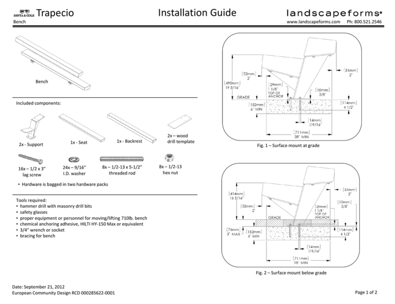
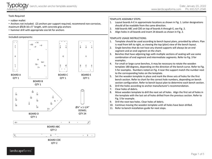
Included components:
Installation Guide
Typology bench
www.landscapeforms.com Ph: 800.521.2546
Date: January 27, 2022
End support Light blocker
2X per light blocker
1/4-20 X 3/8” socket
Button head cap screw Intermediate support
T-strap, straight, end segment “T”
T-strap, straight, intermediate segment “V”
T-strap, small radius,
end segment “J”
T-strap, small radius,
intermediate segment “L”
T-strap, large radius,
end segment “H”
T-strap, large radius,
intermediate segment “C”
8X per T-strap
3/8-16 x 1” torx
Button head cap screw
Concrete seat, straight –2X per bench segment
Concrete seat profile
(for reference)
top
1/4-20 x 1” set screw
4X per concrete section
3/4” O.D. washer
2X per concrete section
1/4-20 hex nut
2X per concrete section
Spacer block kit
1X per support
Plastic support pad
2X per support
Plastic support pad
1X per support
Concrete seat, small radius
Outside section
Concrete seat, small radius
Inside section
Concrete seat, large radius
Outside section
Concrete seat, large radius
Inside section
Page 2 of 8
Included components (continued):
Installation Guide
Typology bench
www.landscapeforms.com Ph: 800.521.2546
Lean back, right arm Lean back, left arm
Lean back, full Lean back, partial
Perch back, full Perch back, partial Perch back, right arm Perch back, left arm
Backless arm
Perpendicular
surface
Left angled
surface
Right angled
surface
5/16-18 x 1-1/4”
socket button
head cap screw
4X in hardware
pack 64824
5/16” I.D. washer
4X in hardware
pack 64824
HARDWARE PACK #64824
1X –ALL ARM STYLES
1X – ALL SURFACES
2X –ALL PARTIAL BACKS
4X –ALL FULL BACKS
Skatestop
Light kit
Date: January 27, 2022
Page 3 of 8
Installation Guide
Typology bench
www.landscapeforms.com Ph: 800.521.2546
Fig. 1 Fig. 2
HOLES ON
BOTH FACES OF
INTERMEDIATE
SUPPORT
OUTSIDE FACE
OF END SUPPORT
NO HOLES
Fig. 3
LEVELING
GLIDES
HOLES
FOR
ANCHORS
Fig. 4
INTERMEDIATE
SEGMENT
END SEGMENT
STRAIGHT BENCH SHOWN
Fig. 6
3/8-16 x 1”
TORX BUTTON
HEAD CAP SCREW
4X PER SIDE
Fig. 7
LEVEL ACROSS
3 SUPPORTS ON
STRAIGHT BENCH
Date: January 27, 2022
Page 4 of 8
Fig. 5
OFFSET SIDE
OF T-STRAP
INTERMEDIATE
SEGMENT
END SEGMENT
NEXT SEGMENT
OF T-STRAPS
SHARED
SUPPORT
NO OFFSET SIDE
OF T-STRAP
Fig. 5A
LETTER CUTOUT
IN STRAP
REFER TO INCLUDED
COMPONENTS
Installation Guide
Typology bench
www.landscapeforms.com Ph: 800.521.2546
Fig. 8
1/4-20 x 3/8”
SOCKET BUTTON
HEAD CAP SCREW
2X PER PANEL
Fig. 9 Fig. 10
INSIDE HOLES
FOR END
SUPPORT
LOCATION
OUTSIDE
HOLES FOR
INTERMEDIATE
SUPPORT
LOCATION
Fig. 12AFig. 11
Date: January 27, 2022
Page 5 of 8
Fig. 13
INSTALL THESE SECTIONS
OF CONCRETE FIRST
Fig. 12B
Installation Guide
Typology bench
www.landscapeforms.com Ph: 800.521.2546
Fig. 14
5/16-18 x 1-1/4”
SBHCS
4X PER SURFACE
SURFACE
WASHER
Fig. 16
BACKLESS ARM
LEAN BACK WITH ARM PERCH BACK WITH ARM
Fig. 15
5/16-18 x 1-1/4” SBHCS
16X PER FULL BACK
FULL BACK
WASHER
Date: January 27, 2022
Page 6 of 8
Installation Guide
Typology bench
www.landscapeforms.com Ph: 800.521.2546
Fig. 20
WASHER
Fig. 19
Fig. 21
SET SCREW
IN CONCRETE
WASHER
HEX NUT
Fig. 17
LED DRIVER
BRACKET
1/4-20 x 3/8”
SBHCS
Fig. 18
CUTOUT IN
T-STRAP
LED
STRIP
PLASTIC
CLIP
ZIP TIE
Date: January 27, 2022
Page 7 of 8
Installation Guide
Typology bench
www.landscapeforms.com Ph: 800.521.2546
Page 8 of 8
Fig. 24
Fig. 22
1/4-20 x 2”
BHCS
WASHER
SPACER
BLOCK
Fig. 23
Date: January 27, 2022
Fig. 25
CONDUIT
LOCATION
OPTIONAL
CONDUIT LOCATION IF
CENTERED UNDER
INTERMEDIATE SUPPORT
OUTER EDGE OF CONCRETE
TO INTERMEDIATE SUPPORT

Other Landscape Forms Outdoor Furnishing manuals

Landscape Forms Trapecio User manual

Landscape Forms

Landscape Forms Trapecio User manual

Landscape Forms Typology User manual

Landscape Forms

Landscape Forms Typology User manual

Landscape Forms Connect 2.0 User manual

Landscape Forms

Landscape Forms Connect 2.0 User manual

Landscape Forms Carousel User manual

Landscape Forms

Landscape Forms Carousel User manual

Landscape Forms Rest bench User manual

Landscape Forms

Landscape Forms Rest bench User manual

Landscape Forms Perisphere User manual

Landscape Forms

Landscape Forms Perisphere User manual

Landscape Forms Marneaux Table User manual

Landscape Forms

Landscape Forms Marneaux Table User manual

Landscape Forms Connect 2.0 User manual

Landscape Forms

Landscape Forms Connect 2.0 User manual

Landscape Forms Connect 2.0 User manual

Landscape Forms

Landscape Forms Connect 2.0 User manual

Landscape Forms Sophie User manual

Landscape Forms

Landscape Forms Sophie User manual

Landscape Forms Typology User manual

Landscape Forms

Landscape Forms Typology User manual

Popular Outdoor Furnishing manuals by other brands

Sunjoy D-BS692SAL Assembly instructions

Sunjoy

Sunjoy D-BS692SAL Assembly instructions

Great Gazebo CROWN Assembly instructions

Great Gazebo

Great Gazebo CROWN Assembly instructions

Gazebo penguin 43224 Assembly instructions

Gazebo penguin

Gazebo penguin 43224 Assembly instructions

Forever Redwood ALAN'S REDWOOD STORAGE BENCH Assembly instructions

Forever Redwood

Forever Redwood ALAN'S REDWOOD STORAGE BENCH Assembly instructions

Gronomics EPB 24-82 Assembly instruction

Gronomics

Gronomics EPB 24-82 Assembly instruction

Backyard Creations Ellington FTS61288 Assembly instructions

Backyard Creations

Backyard Creations Ellington FTS61288 Assembly instructions

Field & Hawken Ambleside Extending Table Assembly instructions

Field & Hawken

Field & Hawken Ambleside Extending Table Assembly instructions

Voyager Dock T-Brace instructions

Voyager Dock

Voyager Dock T-Brace instructions

Sunjoy L-DN879SAL-1-OT Assembly instructions

Sunjoy

Sunjoy L-DN879SAL-1-OT Assembly instructions

Hanover Asher ASHER7PCDN-GRY manual

Hanover

Hanover Asher ASHER7PCDN-GRY manual

Grange TOSCANA CORNER ARBOUR Assembly instructions

Grange

Grange TOSCANA CORNER ARBOUR Assembly instructions

Sunjoy A102023800 Assembly and safety instructions

Sunjoy

Sunjoy A102023800 Assembly and safety instructions

TOPMAQ TSA4524C Assembly instructions

TOPMAQ

TOPMAQ TSA4524C Assembly instructions

Uberhaus 77705076 Operator's manual

Uberhaus

Uberhaus 77705076 Operator's manual

AXI.COM Plantbin user manual

AXI.COM

AXI.COM Plantbin user manual

Costway HW66529 manual

Costway

Costway HW66529 manual

BENITO Iris MA02-1 Assembly instructions

BENITO

BENITO Iris MA02-1 Assembly instructions

Country Living D71 M80480 owner's manual

Country Living

Country Living D71 M80480 owner's manual

manuals.online logo
manuals.online logoBrands
  • About & Mission
  • Contact us
  • Privacy Policy
  • Terms and Conditions

Copyright 2025 Manuals.Online. All Rights Reserved.