Installation Guide
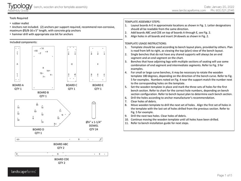
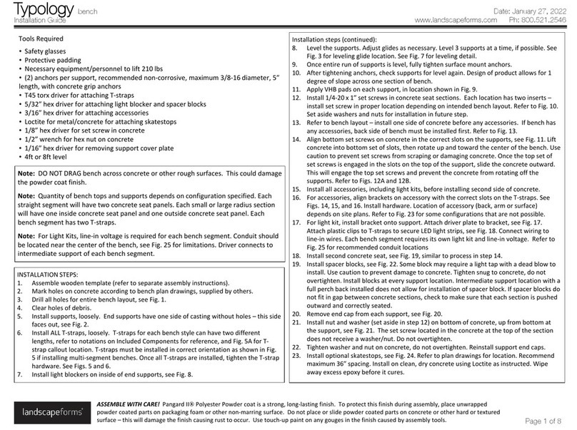
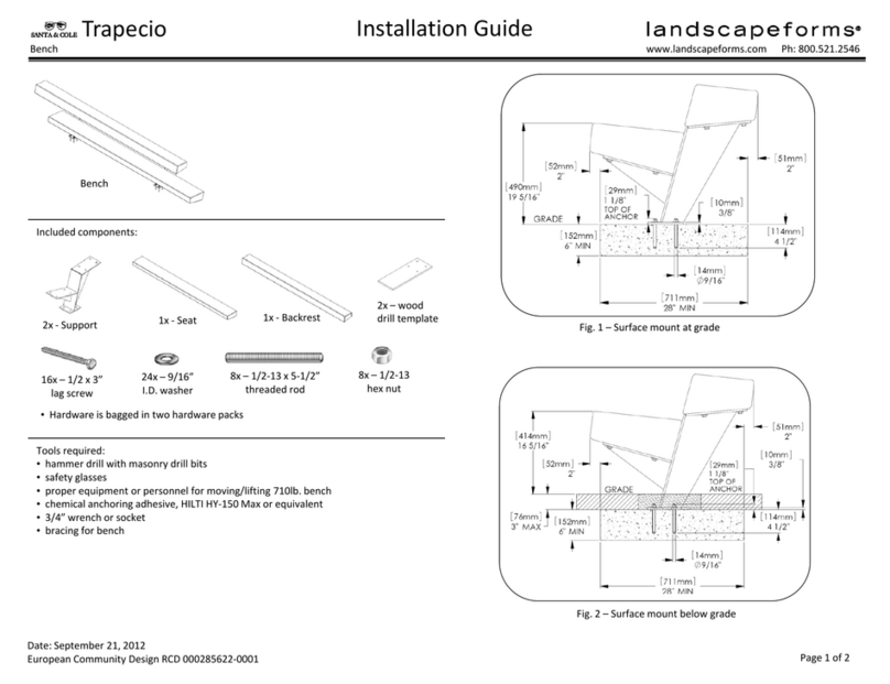
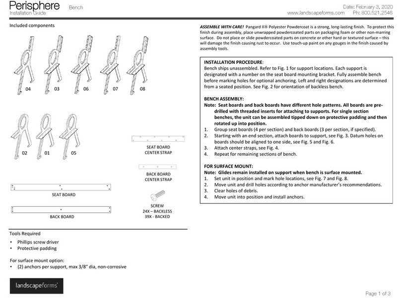
Connect 2.0 Shelter, 8ft solar unit, louvered metal roof assembly
www.landscapeforms.com Ph: 800.521.2546
Date: January 9, 2023
Page 2 of 4
ASSEMBLE WITH CARE! Pangard IIPolyester Powdercoat is a strong, long-lasting finish. To protect this finish during
assembly, place unwrapped powdercoated parts on packaging foam or other non-marring surface. Do not place or slide
powdercoated parts on concrete or other hard or textured surface –this will damage the finish causing rust to occur.
Use touch-up paint on any gouges in the finish caused by assembly tools.
INSTALLATION:
1. Install one set screw in the center threaded hole of each rafter. Head of screw should be flush or just below top
of rafter.
2. Install threaded rods into rafters, see Fig. 4 and Fig. 4A for locations of 6” and 6-1/2” long rods.
3. Set castings in position on rafter, installing over threaded rods. Front and rear castings will overhang the edge of
the rafter, with the hole in the end face of each casting oriented on the outside edge, see Fig. 4.
4. Set louvers in position. The front and rear louvers have holes on the face of the slat. Those holes should be
oriented to the inside of the roof. Each location on the casting for accepting louvers, that isn’t drilled, will have a
locating bump. The holes in the short side of the louver should sit on those bumps.
5. Set second set of castings on top of louvers. Install camtainer nuts loosely on the six 6” threaded rods in the
middle of the center rafter.
6. Using the double ended ratchet and 3/16” bit, install button head cap screws on the front and rear louvers, see
Fig. 4.
7. Install panel stop blocks on rear ends of long c-channels, see Fig. 3, found in hardware pack #62946.
8. Place C channel extrusions on roof, with open channels facing each other as shown in Fig. 4.
9. Loosely install camtainer nuts on threaded rods as shown in Fig. 4. Adjust position of the C channel until the
width between them is 71-1/2” on both ends and the cross diagonal dimensions measure the same. Distance
between short c-channels should be 42-9/16”. See Fig 5.
10. Tighten all hardware.
11. Connect solar panel extension harnesses as shown in Fig. 2.
12. Install junction box cover on solar panel. See Fig. 1 for location. Remove backing on VHB strips and adhere to
clean, dry solar panel.
13. Install long U-shaped gaskets on short edges of solar panel. Install short U-shaped gaskets, centered on long
sides of panel.
14. Using proper glass handling techniques, set solar panel in position on top of C-channels in center of roof.
Junction box should be on the underside of the panel, toward the front of the shelter, see Fig. 6. Connect wires
to connectors that are factory-installed in front horizontal beam. Route wires in between roof panels, down
along front of center rafter, tucking excess wires along side of rafter, see Fig. 8. Rafter skin will be installed after
downlight is installed (see separate instructions).
15. Install L-angles as shown in Fig. 6, placing on top of C-channels until mounting holes align. Use hardware pack
#62946.
16. Proceed to Wall Glass Installation Guide if applicable. If unit is specified with no wall glass, proceed to Solar
Wiring Installation Guide.
WIRING
CONNECTIONS
JUNCTION
BOX
Fig. 1 –install junction box
SHORT U-
GASKET -
2X
LONG U-
GASKET -
2X
Fig. 2 –install junction box
