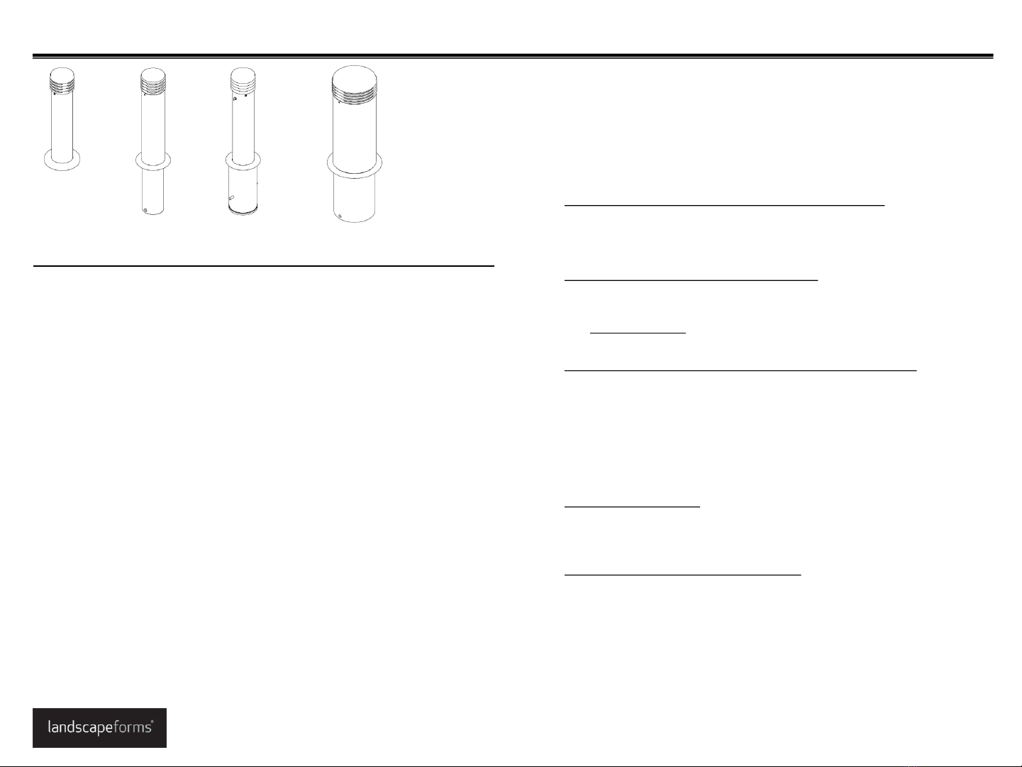
Landscape Forms Annapolis Bollard User manual
Other Landscape Forms Outdoor Light manuals

Landscape Forms
Landscape Forms Typology User manual

Landscape Forms
Landscape Forms Profile Area Light BW402 User manual

Landscape Forms
Landscape Forms Motive User manual

Landscape Forms
Landscape Forms Connect 2.0 User manual

Landscape Forms
Landscape Forms Torres User manual

Landscape Forms
Landscape Forms FGP Path Light User manual

Landscape Forms
Landscape Forms Annapolis Bollard User manual

Landscape Forms
Landscape Forms Lo-Glo User manual

Landscape Forms
Landscape Forms Connect 2.0 User manual

Landscape Forms
Landscape Forms FGP User manual

Landscape Forms
Landscape Forms Ashbery User manual

Landscape Forms
Landscape Forms MultipliCITY Path Light User manual

Landscape Forms
Landscape Forms Torres User manual

Landscape Forms
Landscape Forms Hawthorne User manual

Landscape Forms
Landscape Forms Ashbery User manual

Landscape Forms
Landscape Forms Signal User manual

Landscape Forms
Landscape Forms Profile BW103-2 User manual
Popular Outdoor Light manuals by other brands


HEPER
HEPER DOGO Side LW6048.585-US Installation & maintenance instructions

Maretti
Maretti VIBE S 14.6080.04.A quick start guide

BEGA
BEGA 84 253 Installation and technical information

HEPER
HEPER LW8034.003-US Installation & maintenance instructions

HEPER
HEPER MINIMO Installation & maintenance instructions

LIGMAN
LIGMAN BAMBOO 3 installation manual

Maretti
Maretti TUBE CUBE WALL 14.4998.04 quick start guide

Maxim Lighting
Maxim Lighting Carriage House VX 40428WGOB installation instructions

urban ambiance
urban ambiance UQL1273 installation instructions

TotalPond
TotalPond 52238 instruction manual

Donner & Blitzen
Donner & Blitzen 0-02661479-2 owner's manual

LIGMAN
LIGMAN DE-20023 installation manual