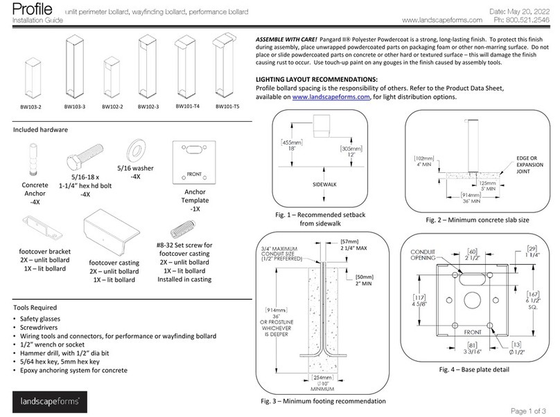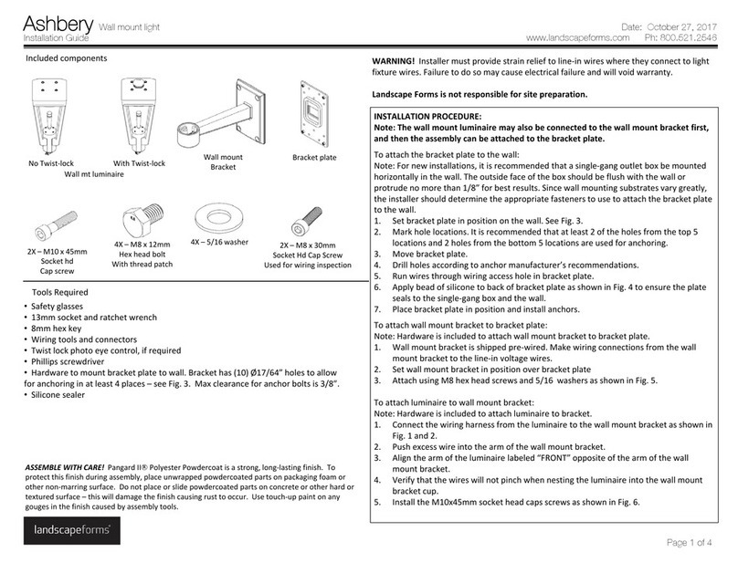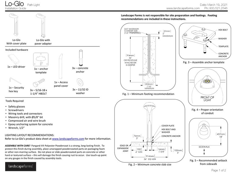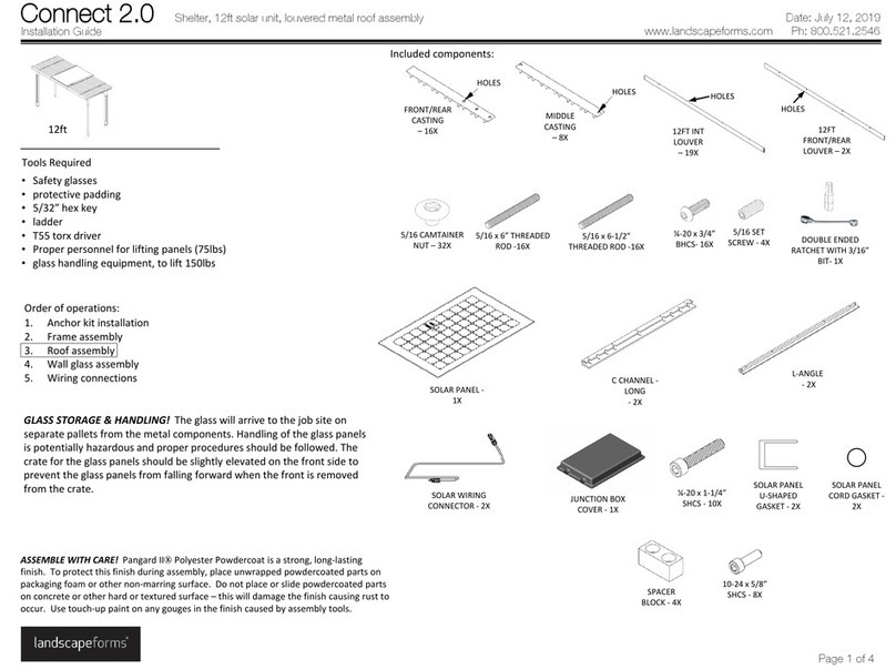
INSTALLATIONPROCEDUREFORLIGHTPOLE:
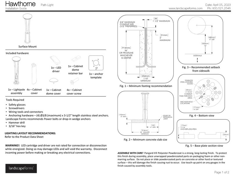
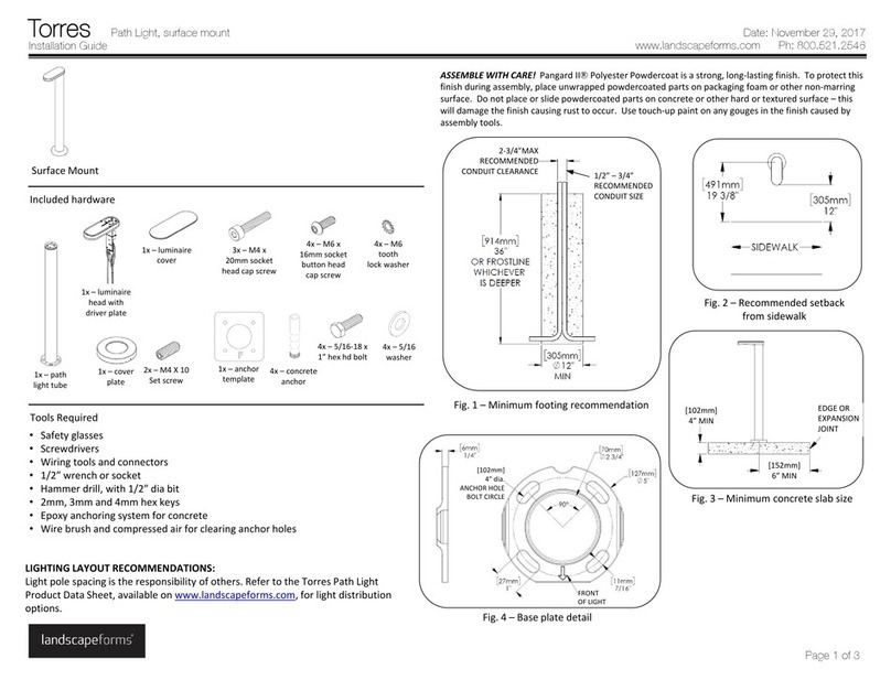
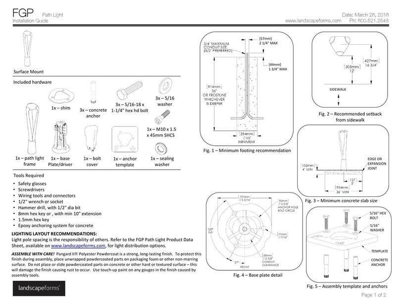
1. Liftthelightpoleintopositionovertheinstalledanchors(refertoFGParealight
anchorkitinstallationguide)asshowninFig.1.Ensurethatthebaseplateisresting
onallfourwashers.
2. Installwashersandhexs nutasshowninFig.2.
3. Plumbandlevelthepoleandtightenallanchors.
4. Connectline‐inwirestodriverplateassembly.Passwiresthroughstrainrelief.See
Fig.3.Refertowiringdiagramsonpage3.
5. Ensurethatthewireharnessconnectorsarepulledthroughthetopofthedriver
plateassemblythroughthefrontcavity.Thisistoconnecttheluminairewiring.
6. Gentlyinsertthedriverplateassemblyintothetopofthepole.Ensurethefrontof
driverplateassemblyisinthecorrectorientation.SeeFig.3and4.
7. Applydownwardpressuretocompressthegasket.Tightenthesixhexboltsequally
usinga13mmwrenchuntilsnug.Ensurethatoncetightened,thedriverplate
assemblyrestsinthecenterofthepole.
8. Connectluminairewiringtodriverplateassembly,seeFig.5.
9. Gentlypushwiresdowninsideofdriverplateassembly.SetLuminaireontopof
driverplateassembly,ensuringthattheluminairemountplateisseatedproperlyon
thetopofthedriverplateassembly.Usean8mmhexkeytoinstallM10x55msocket
headcapscrewandsealingwashertosecureluminairetotopofpole.
10. Iftwistlockreceptacleisspecified,removeshortingcapandinstallphoto‐eyecontrol
(notincluded),seeFig.6.
11. InstallthecoverplateasshowninFig.7and8.Usea5mmhexkeytotighteninternal
socketheadcapscrewstosecurethetwohalvestogether.
ToolsRequired
•Safetyglasses
•Wrenches,1‐1/4”,13mm
•Screwdrivers,Phillipsandstraightblade
•Wiringtoolsandconnectors
•Properpersonnel,craneorliftforhoistingunitontoanchors
•Level
•Dimmingcontrol,ifrequired
•Hexkeys,8mmwith10‐12”extension,5mm
•Twistlockphotoeyecontrol,ifrequired
LandscapeFormsisnotresponsibleforsitepreparationandfootings.Refertothe
installationguidefortheFGPlightanchorkitforinstallingtheanchorbolts.
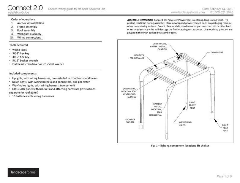
CAUTION! Thisunitisheavy.Toavoidinjuryordamagetothefinish,werecommend
usingacraneorliftforhoistingtheunitontotheanchors.
WARNING! Polemountedluminairesmustbeattachedeitherbeforeorimmediately
afterpoleinstallation. Failuretodosomaycausevibrationdamagetothepoleandwill
voidthepolewarranty.
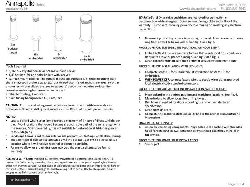
ASSEMBLEWITHCARE! Pangard IIPolyesterPowdercoat isastrong,long‐lastingfinish.To
protectthisfinishduringassembly,placeunwrappedpowdercoated partsonpackagingfoamor
othernon‐marringsurface.Donotplaceorslidepowdercoated partsonconcreteorotherhard
ortexturedsurface– thiswilldamagethefinishcausingrusttooccur.Usetouch‐uppaintonany
gougesinthefinishcausedbyassemblytools.
Luminaire
2x‐ Coverplatehalf Twistlockreceptacle,
optional
Installation Guide
FGP Area Light
www.landscapeforms.com Ph: 800.521.2546
Date: October 5, 2018
Page 1 of 3
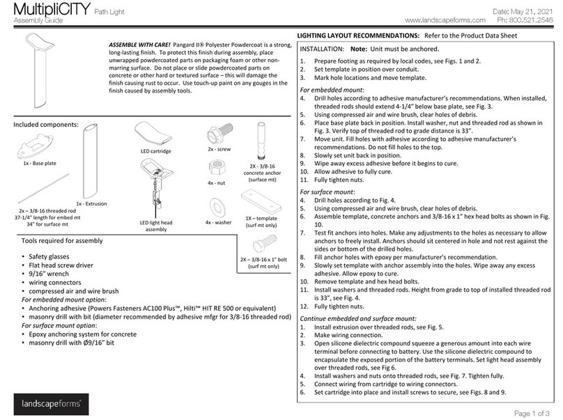
Includedcomponents
Shortingcapfor
Twistlock,optional
Pole
Driverplate
assembly 1x‐ M10x1.5x55mm
socketheadcapscrew
withsealingwasher
INSTALLATIONPROCEDURE FOROPTIONALPHOTOEYE:
Refertowiringdiagramforwiringdetails.
1. Removethetwistlockcapfromthetopofthelight.
2. Loosenthetwophillips headscrewstwoturns.
IMPORTANT!Donotremovethescrews.Loosenjustenoughtorotatethereceptacle.
3. Rotatethereceptacleuntilthearrowpointsnorth.Tightenthescrews.
4. Installthephotoeye(notsuppliedwithunit)ratedforproperlinevoltage(277v,
1.5A).

