ASSEMBLEWITHCARE! Pangard IIPolyesterPowdercoat isastrong,long‐lastingfinish.To
protectthisfinishduringassembly,placeunwrappedpowdercoated partsonpackagingfoamor
othernon‐marringsurface.Donotplaceorslidepowdercoated partsonconcreteorotherhardor
texturedsurface– thiswilldamagethefinishcausingrusttooccur.Usetouch‐uppaintonany
gougesinthefinishcausedbyassemblytools.
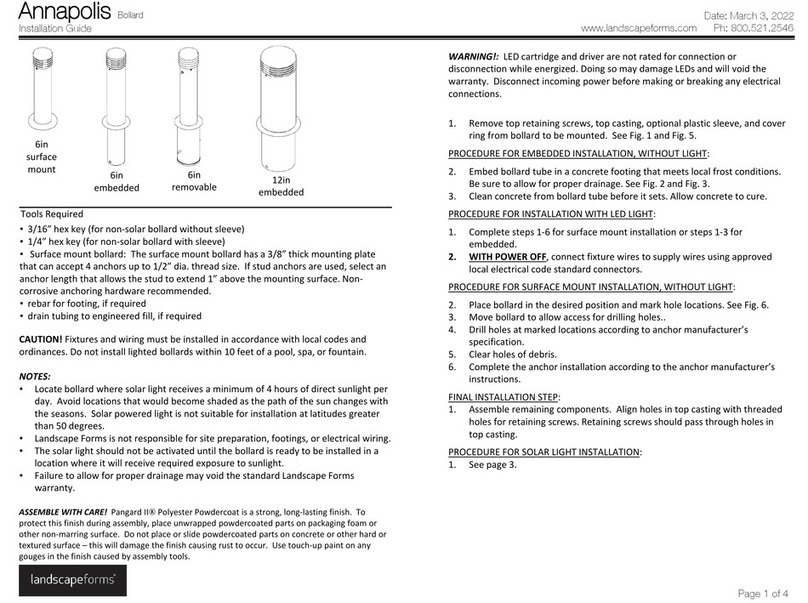
1. Removetopretainingscrews,topcasting,optionalplasticsleeve,andcoverringfrom
bollardtobemounted.SeeFig.1andFig.5.
PROCEDUREFOREMBEDDEDINSTALLATION,WITHOUTLIGHT:
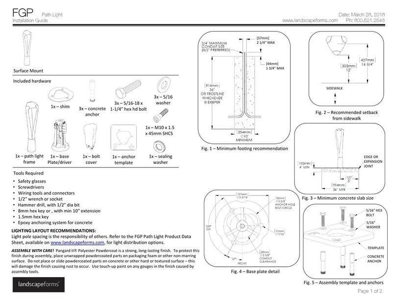
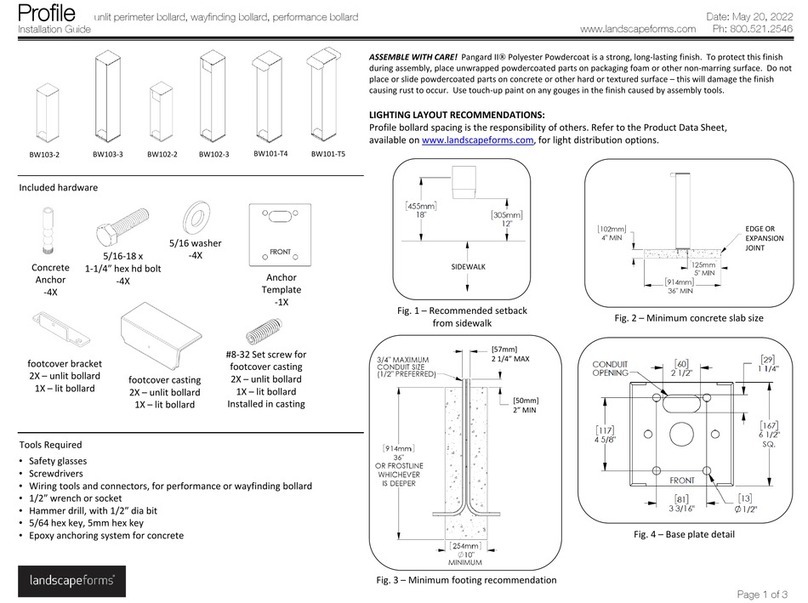
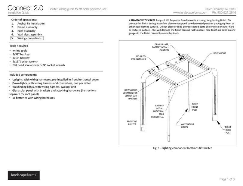
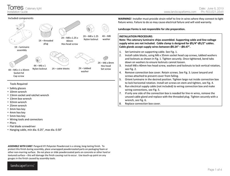
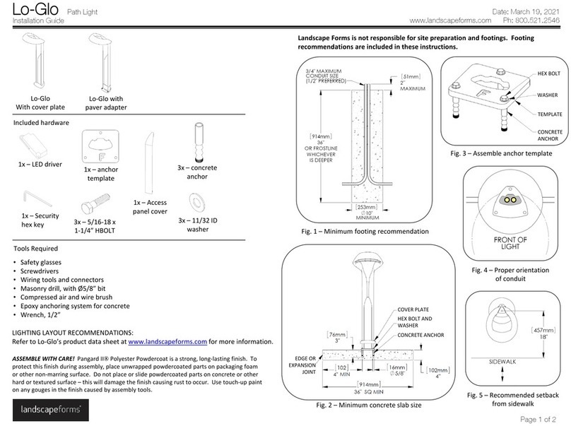
2. Embedbollardtubeinaconcretefootingthatmeetslocalfrostconditions.Besureto
allowforproperdrainage.SeeFig.2andFig.3.
3. Cleanconcretefrombollardtubebeforeitsets.Allowconcretetocure.
PROCEDUREFORINSTALLATIONWITHLEDLIGHT:
1. Completesteps1‐6forsurfacemountinstallationorsteps1‐3forembedded.
2. UnpacktheLEDlightfixture.Refertolightmanufacturer’sinstructionspackedwith
fixture.
3. WITHPOWEROFF,connectfixturewirestosupplywiresusingapprovedlocal
electricalcodestandardconnectors.
4. AttachLEDlightassemblytoLEDmountingbracketwithtwo8‐32x1/2”socketbutton
headcapscrews.Tightensecurely.SeeFig.4andFig.6.
5. Feedfixturewireintobollard.Usingtwo8‐32x1/2”buttonheadcapscrews,attach
LEDlightassemblytoretainerbracket.Tightensecurely.
PROCEDUREFORSURFACEMOUNTINSTALLATION,WITHOUTLIGHT:
2. Placebollardinthedesiredpositionandmarkholelocations.SeeFig.6.
3. Movebollardtoallowaccessfordrillingholes..
4. Drillholesatmarkedlocationsaccordingtoanchormanufacturer’sspecification.
5. Clearholesofdebris.
6. Completetheanchorinstallationaccordingtotheanchormanufacturer’sinstructions.
FINALINSTALLATIONSTEP:
1. Assembleremainingcomponents.Alignholesintopcastingwiththreadedholesfor
retainingscrews.Retainingscrewsshouldpassthroughholesintopcasting.
PROCEDUREFORSOLARLIGHTINSTALLATION:
1. Removetopretainingscrews,topcastingwithsolarlight,optionalplasticsleeve,and
coverringfrombollardtobemounted.Solarlightandbatterybracketremainattached
totopcastingwithwingnuts.
NOTE:Solarbollardsareshippedwithapin‐in‐hexkeyforsecurityscrews.DoNOTconnect
thebatterywireuntilStep4.
2. Completesurfacemountinstallationsteps1‐6orembeddedinstallationsteps1‐3.
3. Assemblecoverringandoptionalsleeve.
4. SetbatteryonshelfofbracketandsecurewithVelcrostrap.
5. Connectredbatterywiretored(positive)batteryterminal,seeFig.7.Connectblack
batterywiretoblack(negative)terminal.
6. Assembletopcastingwithsolarlightandbatterytothebollardtube.Alignholesin
topcastingwiththreadedholesforretainingscrews.Retainingscrewsshouldpass
throughholesintopcasting.
•3/16”hexkey(fornon‐solarbollardwithoutsleeve)
•1/4”hexkey(fornon‐solarbollardwithsleeve)
•Surfacemountbollard:Thesurfacemountbollardhasa3/8”thickmountingplate
thatcanaccept4anchorsupto1/2”threadsize.Ifstudanchorsareused,selectan
anchorlengththatallowsthestudtoextend1”abovethemountingsurface.Non‐
corrosiveanchoringhardwarerecommended.
•rebarforfooting,ifrequired
•draintubingtoengineeredfill,ifrequired
ToolsRequired
Installation Guide
Annapolis Bollard
www.landscapeforms.com Ph: 800.521.2546
Date: July 20, 2018
Page 1 of 4
6in
surface
mount 6in
embedded
6in
removable 12in
embedded
CAUTION!Fixturesandwiringmustbeinstalledinaccordancewithlocalcodesand
ordinances.Donotinstalllightedbollardswithin10feetofapool,spa,orfountain.
NOTES:
•Locatebollardwheresolarlightreceivesanaverageof4hoursofdirectsunlightper
day.Avoidlocationsthatwouldbecomeshadedasthepathofthesunchangeswith
theseasons.Solarpoweredlightisnotsuitableforinstallationatlatitudesgreater
than50degrees.
•LandscapeFormsisnotresponsibleforsitepreparation,footings,orelectricalwiring.
•Thesolarlightshouldnotbeactivateduntilthebollardisreadytobeinstalledina
locationwhereitwillreceiverequiredexposuretosunlight.
•FailuretoallowforproperdrainagemayvoidthestandardLandscapeForms
warranty.

