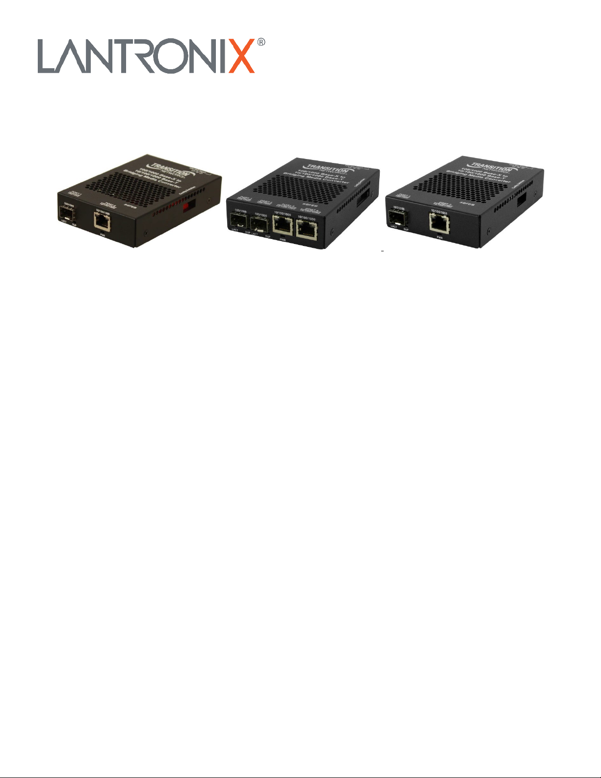
Lantronix SGFEB Series User Guide
33601 Rev. E https://www.lantronix.com 3
Contents
Introduction .......................................................................................................................................................................... 4
Ordering Information............................................................................................................................................................ 4
Optional Accessories (sold separately) ............................................................................................................................... 4
Power Supply Included .................................................................................................................................................... 4
For More Information ........................................................................................................................................................... 5
Package Contents ............................................................................................................................................................... 7
Status LEDs ................................................................................................................................................................... 13
Fiber Status LEDs.......................................................................................................................................................... 13
Copper Status LEDs ...................................................................................................................................................... 13
Auto-Negotiation ............................................................................................................................................................ 14
Link Pass-Through (LPT)............................................................................................................................................... 14
Full-Duplex Network....................................................................................................................................................... 14
Half-Duplex Network (512-Bit Rule)............................................................................................................................... 14
AutoCross™................................................................................................................................................................... 14
Automatic Link Restoration ............................................................................................................................................ 15
Far End Fault (FEF) ....................................................................................................................................................... 15
Remote Fault Detect (RFD) ........................................................................................................................................... 15
Fiber Redundancy (Revertive / Non-revertive) .............................................................................................................. 15
New Features................................................................................................................................................................. 15
Port Isolation on 3-Port Models ..................................................................................................................................... 16
Port Isolation on 4-Port Models ..................................................................................................................................... 17
Cable Specifications .......................................................................................................................................................... 18
Copper Cable Specs...................................................................................................................................................... 18
TP Port Specs ................................................................................................................................................................ 18
Fiber Cable Specs ......................................................................................................................................................... 19
Technical Specifications................................................................................................................................................. 20
Declaration of Conformity .............................................................................................................................................. 24
CE .................................................................................................................................................................................. 24
FCC................................................................................................................................................................................ 24
Canadian........................................................................................................................................................................ 24
European........................................................................................................................................................................ 25
RoHS, WEEE, and Environmental Programs ................................................................................................................ 25
Product Registration .......................................................................................................................................................... 25