Lantronix ION C2210 User manual

ION C2210
Fast Ethernet Media and Rate Converter Module
10/100Base-TX to 100Base-FX
Installation Guide
Part Number 33416
Revision B August 2023

Lantronix ION C2210 Installation Guide
33416 Rev. B https://www.lantronix.com Page 2of 17
Intellectual Property
© 2022, 2023 Lantronix, Inc. All rights reserved. No part of the contents of this publication may be transmitted or
reproduced in any form or by any means without the written permission of Lantronix.
Lantronix is a registered trademark of Lantronix, Inc. in the United States and other countries.
All other trademarks and trade names are the property of their respective holders.
Patented: https://www.lantronix.com/legal/patents/; additional patents pending.
Warranty
For details on the Lantronix warranty policy, go to http://www.lantronix.com/support/warranty.
Contacts
Lantronix Corporate Headquarters
48 Discovery, Suite 250
Irvine, CA 92618, USA
Toll Free: 800-526-8766
Phone: 949-453-3990
Fax: 949-453-3995
Technical Support
Online: https://www.lantronix.com/technical-support/
Sales Offices
For a current list of our domestic and international sales offices, go to www.lantronix.com/about/contact.
Disclaimer
All information contained herein is provided “AS IS.” Lantronix undertakes no obligation to update the information
in this publication. Lantronix does not make, and specifically disclaims, all warranties of any kind (express, implied
or otherwise) regarding title, non-infringement, fitness, quality, accuracy, completeness, usefulness, suitability or
performance of the information provided herein. Lantronix shall have no liability whatsoever to any user for any
damages, losses and causes of action (whether in contract or in tort or otherwise) in connection with the user’s
access or usage of any of the information or content contained herein. The information and specifications
contained in this document are subject to change without notice.
Revision History
Rev
Date
Description
A
7/29/2010
Initial release.
B 8/31/23
Initial Lantronix re-brand. FW v 1.2.0: add note on DIP switches. Add minor editorial and
technical changes. FW v 2.0.0 and Boot Loader v 0.1.5: change slot ID to read an analog
voltage to prevent a wrong slot number.

Lantronix ION C2210 Installation Guide
33416 Rev. B https://www.lantronix.com Page 3of 17
Contents
Product Description ............................................................................................................................................. 4
Ordering Information............................................................................................................................................ 4
Features ................................................................................................................................................................. 4
Manageable Features ..................................................................................................................................... 4
Specifications ....................................................................................................................................................... 5
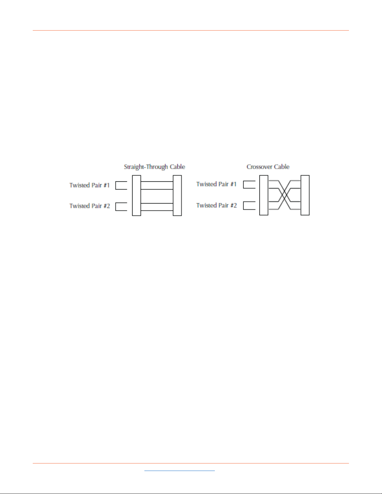
Cable Specifications............................................................................................................................................ 7
Fiber cable....................................................................................................................................................... 7
Copper cable ................................................................................................................................................... 8
Installation ............................................................................................................................................................. 9
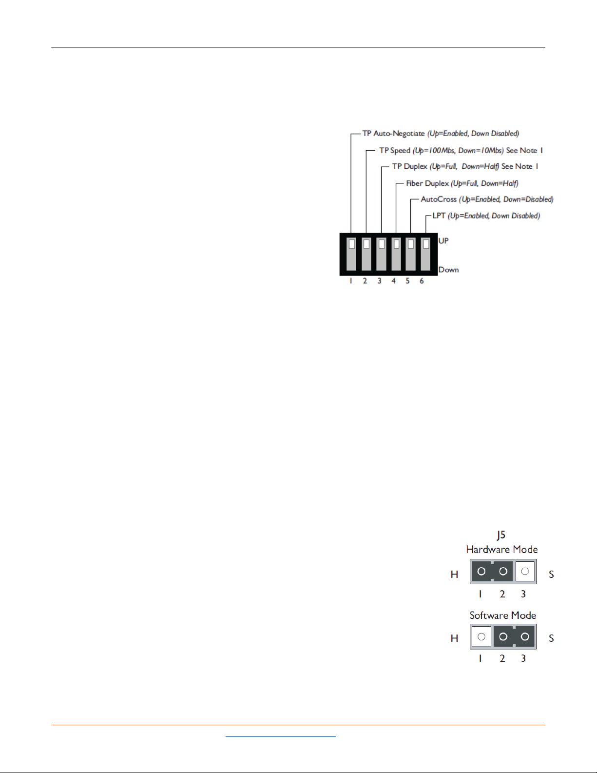
Set the 6-position DIP Switch ............................................................................................................................. 9
Hardware/software Mode Jumper....................................................................................................................... 9
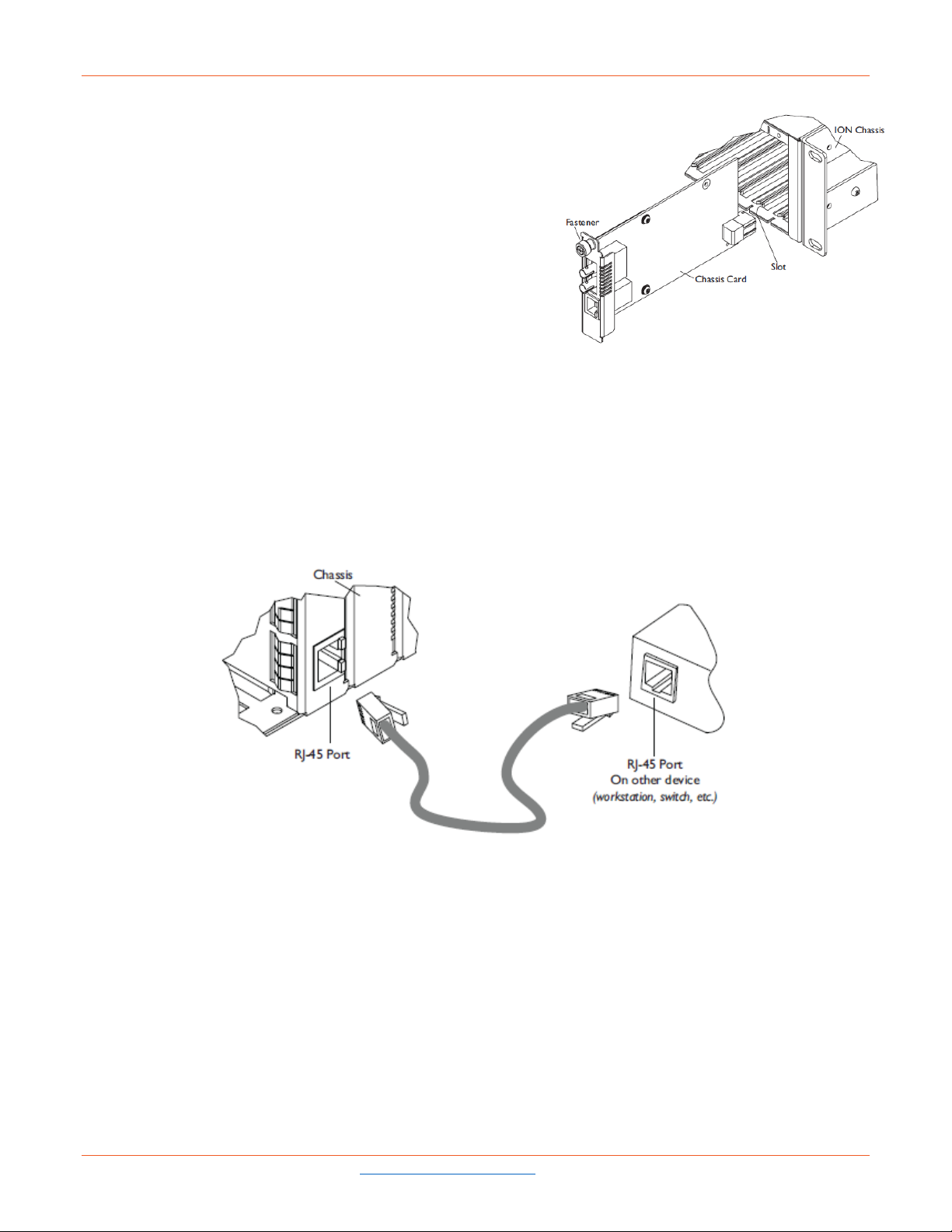
Install the C2210 SIC ........................................................................................................................................ 10
Power the C2210 SIC ....................................................................................................................................... 10
Install the Twisted-pair Copper Cable ............................................................................................................... 10
Install the Fiber Cable ........................................................................................................................................11
Operation............................................................................................................................................................. 11
Status LEDs .......................................................................................................................................................11
Product features................................................................................................................................................ 12
AutoCross™ .................................................................................................................................................. 12
Link pass-through .......................................................................................................................................... 12
Far-end fault .................................................................................................................................................. 12
Auto-Negotiation............................................................................................................................................ 12
Parallel detection ........................................................................................................................................... 12
SNMP ............................................................................................................................................................ 13
Troubleshooting ................................................................................................................................................. 14
Compliance Information .................................................................................................................................... 15
FCC regulations ................................................................................................................................................ 15
Canadian regulations ........................................................................................................................................ 15
European regulations ........................................................................................................................................ 15
Declaration of Conformity ................................................................................................................................. 16

Lantronix ION C2210 Installation Guide
33416 Rev. B https://www.lantronix.com Page 4of 17
Product Description
The ION C2210 is a media converter module that provides an interface between 10/100Base-TX ports and
100Base-FX ports, allowing users to integrate fiber optic cabling into 10/100 copper environments. Operating at
Layer 2, the data link layer, this converter not only converts copper to fiber, it also provides rate conversion
allowing legacy 10Base-T copper devices to connect to 100Base-FX fiber. The ION C2210 is a manageable
device when installed in a managed ION chassis.
Ordering Information
Part Number Port 1 – Copper 10/100-Base-T Port 2 - Duplex Fiber-Optic 100Base-FX
C2210-1011 RJ-45; 100 m (328 ft) ST, 1300 nm multimode; 2 km (1.2 miles)*
C2210-1013 RJ-45; 100 m (328 ft) SC, 1300 nm multimode; 2 km (1.2 miles)*
C2210-1014 RJ-45; 100 m (328 ft) SC, 1300 nm single mode; 20 km (12.4 miles)
C2210-1019 RJ-45; 100 m (328 ft) LC, 1300 nm multimode; 2Km (1.2 miles)*
C2210-1039 RJ-45; 100 m (328 ft) LC, 1300 nm multimode; 20Km (12.4 miles)*
C2210-1040 RJ-45; 100 m (328 ft) SFP slot (empty)
*Typical maximum cable distance. Actual distance depends on network physical characteristics.
** Install C2210-1029-xx and C2210-1029-xx single-fiber optic in the same network where one is the local
converter and the other is the remote converter.
Features
•Fast Ethernet
•One Copper & One Fiber Port
•10/100Base-TX to 100Base-FX Connectivity
•Auto-Negotiation of speed and duplex on TP port
•Auto-MDI/MDIX on TP port
•Link Pass Through (LPT)
•Far-End-Fault (FEF) detection
•Pause (Software Controlled)
•Automatic Link Restoration
•Field Upgradeable Firmware
•Can be used in any ION Platform Chassis
•Standards based, will link with any Standard 10/100Base-TX and any Standard 100Base-FX ports
Manageable Features
•Report converter status to chassis management software:
oTP and Fiber Link Status
oHardware switch settings
oCopper Port Speed
oTP and Fiber Port Duplex
oFault condition
•Write operation includes:
oPower on/off device
oAuto-Negotiation enable/disable
oForce 10 Mbps or 100 Mbps
oForce half or full-duplex
oSelect advertising modes when
oAuto-Negotiation is enabled

Lantronix ION C2210 Installation Guide
33416 Rev. B https://www.lantronix.com Page 5of 17
oLPT enable/disable
oFEF enable/disable
oPause enable/disable
oAuto-MDI/MDIX enable/disable
Note: Manageable Features are available when used in an ION Platform chassis along with an ION Management
Module.
Specifications
Standards: IEEE 802.3u, IEEE 802.3x
Data Rate: 10 Mbps; 100 Mbps Layer 2
MAC Address Table: 1K
Frame Buffer Memory: 512 Kbits
Max Frame Size: 2048 bytes
Packet Size: Unicast MAC address: 1K
Maximum packet size:
- 2048 bytes untagged bytes
- 2044 bytes tagged bytes
DIP Switch:
SW1: Auto-Negotiation (UP = enabled)
SW2: Forced 100 Mbps/10 Mbps with Auto-Neg. off (UP = 100 Mbps)
SW3: Forced Full/Half-Duplex with Auto-Neg. off (UP = Full)
SW4: Full/Half-Duplex on fiber port (UP = Full)
SW5: Auto-MDI/MDIX on UTP (UP = enabled)
SW6: Link Pass Through (UP = enabled)
Internal Jumpers: Auto-MDI/MDIX: Enable/Disable
Jumpers:
Hardware: Mode of operation is determined by the settings on the 4-position switch.
Software: Mode of operation is determined by the most recently saved on-board microprocessor settings.
Status LEDs:
FD (Fiber Duplex): ON= Full-duplex on fiber
LACT (Fiber Link/Activity): ON = Fiber Link
PWR (Power): ON=Connection to powered backplane
(TP. Duplex/Link): Yellow = Half duplex, Green = Full-Duplex
(TP. Speed): Yellow = 10Mbps, Green = 100 Mbps
Dimensions: Width: 0.86” [22 mm] x Depth: 6.5” [165 mm] x Height: 3.4”[86 mm]
Power Consumption: 2.5 Watts, 200 mA @ 13.9 VDC
Environment: Environment specs depend on the chassis chosen.
Operating Temp: 0°C to 50°C
Humidity: 5% to 95% (non-condensing)
Altitude: 0 – 10,000 ft.
Weight: 1 lb. [0.45 kg]

Lantronix ION C2210 Installation Guide
33416 Rev. B https://www.lantronix.com Page 6of 17
MTBF:
Greater than 250,000 hours (MIL-HDBK-217F)
Greater than 667,500 hours (Bellcore)
Certifications: CISPR/EN55022 Class A, FCC Class A, CE Mark, EN55024
Warranty: Lifetime
The information in this user’s guide is subject to change. For the most up-to-date information on the C2210 SIC,
view the user’s guide on-line at https://www.lantronix.com/products/c2210-series/.
CAUTION: Visible and invisible laser radiation when open. Do not stare into beam or view directly with optical
instruments.
CAUTION: Use of controls, adjustments or the performance of procedures other than those specified herein may
result in hazardous radiation exposure.
The fiber optic transmitters on this device meet Class I Laser safety requirements per IEC-825/CDRH standards
and comply with 21 CFR1040.10 and 21CFR1040.11.
CAUTION: Copper based media ports, e.g., Twisted Pair (TP) Ethernet, USB, RS232, RS422, RS485, DS1, DS3,
Video Coax, etc., are intended to be connected to intrabuilding (inside plant) link segments that are not subject to
lightening transients or power faults. Copper based media ports, e.g., Twisted Pair (TP) Ethernet, USB, RS232,
RS422, RS485, DS1, DS3, Video Coax, etc., are NOT to be connected to interbuilding (outside plant) link
segments that are subject to lightening transients or power faults. Failure to observe this caution could result in
damage to equipment.

Lantronix ION C2210 Installation Guide
33416 Rev. B https://www.lantronix.com Page 7of 17
Cable Specifications
The physical characteristics must meet or exceed IEEE 802.3™ specifications.
Fiber cable
Bit Error Rate: <10-9
Single mode fiber (recommended): 9 μm
Multimode fiber (recommended): 62.5/125 μm
Multimode fiber (optional): 50/125 μm
C2210-1011 1300 nm multimode
Fiber Optic Transmitter Power: min: -19.0 dBm max: -14.0 dBm
Fiber Optic Receiver Sensitivity: min: -30.0 dBm max: -14.0 dBm
Link Budget: 11.0 dB
C2210-1013 1300 nm multimode
Fiber Optic Transmitter Power: min: -19.0 dBm max: -14.0 dBm
Fiber Optic Receiver Sensitivity: min: -30.0 dBm max: -14.0 dBm
Link Budget: 11.0 dB
C2210-1014 1300 nm single mode
Fiber-optic Transmitter Power: min: -15.0 dBm max: -8.0 dBm
Fiber-optic Receiver Sensitivity: min: -31.0 dBm max: -8.0 dBm
Link Budget: 16.0 dB
C2210-1019 1300 nm single mode
Fiber-optic Transmitter Power: min: -15.2 dBm max: -8.0 dBm
Fiber-optic Receiver Sensitivity: min: -32.5 dBm max: -3.0 dBm
Link Budget: 17.3 dB
C2210-1039 1300 nm multimode
Fiber-optic Transmitter Power: min: -19.0 dBm max: -8.0 dBm
Fiber-optic Receiver Sensitivity: min: -30.0 dBm max: -3.0 dBm
Link Budget: 11 dB
The fiber optic transmitters on this device meet Class I Laser safety requirements per IEC-825/CDRH standards
and comply with 21 CFR1040.10 and 21CFR1040.11.

Lantronix ION C2210 Installation Guide
33416 Rev. B https://www.lantronix.com Page 8of 17
Copper cable
Category 3: (Minimum requirement for 10 Mb/s operation)
Gauge 24 to 22 AWG
Attenuation 11.5 dB/100m @ 5-10 MHz
Category 5: (Minimum requirement for 100 Mb/s operation)
Gauge 24 to 22 AWG
Attenuation 22.0 dB /100m @ 100 MHz
•Straight-through (MDI) or crossover (MDI-X) twisted-pair cable must be used.
•Shielded twisted-pair (STP) or unshielded twisted-pair (UTP) may be used.
•Pins 1&2 and 3&6 are the two active pairs in an Ethernet network .
•Use only dedicated wire pairs for the active pins (e.g., blue/white & white/blue, orange/white & white/orange,
etc.)
•Do not use flat or silver satin wire.

Lantronix ION C2210 Installation Guide
33416 Rev. B https://www.lantronix.com Page 9of 17
Installation
CAUTION: Wear a grounding device and observe electrostatic discharge precautions when setting the 6-position
switch, removing and inserting circuit board jumper(s), and installing the SIC. Failure to observe this caution could
result in damage to or failure of the SIC.
Set the 6-position DIP Switch
•The 6-position DIP switch is located on the side of the SIC.
•Use a small flat blade screwdriver or a similar tool to set
the recessed switches.
•Refer to the drawing to the right for the locations of the
individual switches.
Note 1: Auto-Negotiation must be OFF.
1. TP Auto-Negotiation (See Note 1.)
up Enables Auto-Negotiation on the copper port.
down Disables Auto-Negotiation on the copper port.
2. TP Speed (See Note 1.)
up 100 Mbps operation on the copper port.
down 10 Mbps operation on the copper port.
3. TP Copper Mode
up full duplex operation on the copper port.
down half duplex operation on the copper port.
4. Fiber Mode
up Forces full duplex operation on the fiber port.
down Forces half duplex operation on the fiber port.
5. TP AutoCross
up Enabled.
down Disabled
6. Link Pass Through (LPT)
up Enabled
down Disabled
Hardware/software Mode Jumper
The jumpers are located on the SIC circuit board. Use a small needle-nosed pliers or a
similar tool to set the jumper.
The Hardware/Software jumper is labeled “H” for hardware and “S” for software.
Hardware: The mode of operation of the media converter is determined by the 6-position
switch settings. The default is the Hardware mode position.
Software: The mode of operation of the media converter is determined by the most
recently saved on-board microprocessor settings.

Lantronix ION C2210 Installation Guide
33416 Rev. B https://www.lantronix.com Page 10 of 17
Install the C2210 SIC
To install the C2210 SIC:
1. Locate an empty installation slot on the ION chassis.
2. Carefully slide the module into the installation slot, aligning the
module with the installation guides.
3. Ensure that the module is firmly seated to the chassis
backplane.
4. Push in and rotate the panel fastener screw to secure the
module to the chassis front.
Power the C2210 SIC
The C2210 module SIC is powered through the ION chassis.
Install the Twisted-pair Copper Cable
1. Locate IEEE 803.2 compliant 10Base-T or 100Base-TX cable with RJ-45 connectors installed on both ends.
2. Connect the RJ-45 connector at one end of the cable to the RJ-45 port connector on the SIC.
3. Connect the RJ-45 connector at the other end of the cable to the RJ-45 port connector on the other device
(switch, workstation, etc.).
Note: The MDI (straight-through) or MDI-X (crossover) cable connection is configured automatically, when the
AutoCross jumper is in the enabled position.

Lantronix ION C2210 Installation Guide
33416 Rev. B https://www.lantronix.com Page 11 of 17
Install the Fiber Cable
1. Locate or build IEEE 803.2™ compliant 100Base-FX fiber cable with male, two-stranded TX to RX connectors
installed at both ends.
2. Connect the fiber cables to the C2210 SIC as described:
• Connect the male TX cable connector to the female TX connector.
• Connect the male RX cable connector to the female RX connector.
3. Connect the fiber cables to the other device (SIC, hub, etc.) as described:
• Connect the male TX cable connector to the female RX connector.
• Connect the male RX cable connector to the female TX connector.
Operation
Status LEDs
Use the status LEDs to monitor the SIC and the network connections.
FD (Fiber Duplex)
ON = Full duplex fiber connection.
OFF = Half duplex fiber connection.
LACT (Fiber Link)
ON = Fiber link connection.
Blink = Fiber network activity
PWR (Power)
ON = Power applied to chassis card
TP LED 1 (Twisted-Pair Speed)
ON Green = 100 Mb/s
ON Yellow = 10 Mb/s
TP LED 2 (Twisted Pair Duplex)
ON Green = Full duplex, blink activity
ON Yellow = Half duplex, blink activity

Lantronix ION C2210 Installation Guide
33416 Rev. B https://www.lantronix.com Page 12 of 17
Product features
AutoCross™
The AutoCross feature detects and configures the twisted-pair copper port on the C2210 SIC for the correct
straight-through (MDI) or crossover (MDI-X) configuration. This feature allows either MDI or MDI-X cable to
connect the SIC to devices such as hubs, transceivers, or network interface cards (NICs). (This feature does not
require operator intervention.)
Link pass-through
The Link Pass-Through feature allows the SIC to monitor RX (receive) ports for loss of signal. In the event of a
loss of an RX signal on one media port, the SIC will automatically disable the TX (transmit) signal of the other
media port, thus “passing through” the link loss.
Far-end fault
When a fault occurs on an incoming fiber link (1), the SIC transmits a Far-End Fault signal on the outgoing fiber
link (2). In addition, the Far-End Fault signal also activates Link Pass-Through, which, in turn, disables the link on
the copper portion of the network (3) and (4).
Auto-Negotiation
The Auto-Negotiation feature allows the C2210 SIC to automatically configure itself to achieve the best possible
mode of operation over a link. The SIC will broadcast its speed (10 Mbps or 100 Mbps) and duplex capabilities
(full or half) to the other devices and negotiates the best mode of operation. Auto-Negotiation allows quick and
easy installation because the optimal link is established automatically. No user intervention is required to
determine the best mode of operation.
A scenario where the SIC is linked to a non-negotiating device, you may want to disable Auto-Negotiation. In this
instance, the mode of operation will drop to the least common denominator between the two devices (e.g. 100
Mbps, half duplex). Disabling this feature gives the user the ability to force the connection to the best mode of
operation.
Parallel detection
Parallel detection is the method used to link when an auto negotiating port detects a link partner that is in forced
mode and therefore cannot participate in the auto negotiating process. Parallel Detection can be set to IEEE
Standard half duplex, or the non-standard full duplex. Switch settings for parallel detection are valid in hardware
or software mode, only when Auto-Negotiation is enabled.

Lantronix ION C2210 Installation Guide
33416 Rev. B https://www.lantronix.com Page 13 of 17
Per the IEEE method, an auto negotiating port that detects a forced link partner should drop to the detected
speed (10Mbps or 100Mbps) and default to HALF DUPLEX. The C2210 allows bypassing the IEEE method by
setting the parallel detection default mode to half or full duplex DIP SW 3, disabling SW 1, auto-negotiation and
configuring SW 2, speed.
Full duplex network
In a full duplex network, maximum cable lengths are determined by the type of cables that are used.
Half duplex network (512-Bit Rule)
In a half-duplex network, the maximum cable lengths are determined by the round trip delay limitations of each
Fast Ethernet collision domain. (A collision domain is the longest path between any two terminal devices, e.g., a
terminal, switch, or router, etc.)
The 512-Bit Rule determines the maximum length of cable permitted by calculating the round-trip delay in bit-
times (BT) of a particular collision domain. If the result is less than or equal to 512 BT, the path is good.
SNMP
Use SNMP at an attached terminal or at a remote location to monitor the SIC by monitoring:
• Power
• Serial and part number
• Port number
• Copper and fiber link status
• Copper and fiber duplex mode
• Copper port speed
• Hardware switch setting
Also, use SNMP to enter network commands that do the following:
• Enable/disable Auto-Negotiation on copper
• Force 10Mbps or 100Mbps on copper
• Force full duplex or half duplex on copper
• Force full duplex or half duplex on fiber
• Enable/disable Far-End Fault on fiber
• Enable/disable Link Pass Through
• Enable/disable Pause

Lantronix ION C2210 Installation Guide
33416 Rev. B https://www.lantronix.com Page 14 of 17
Troubleshooting
If the C2210 SIC fails, isolate and correct the failure by determining the answers to the following questions and
then taking the indicated action:
1. Is the PWR (power) LED lit?
NO
• Is the SIC inserted properly into the chassis?
• Is the power cord properly installed in the chassis and in to the external power source; is the external power
source active?
• Contact Technical Support.
YES
• Proceed to step 2.
2. Is the TP LED 1 (twisted-pair) LED lit?
NO
• Check the copper cables for proper connection and pin assignment.
• Contact Technical Support.
YES
• Proceed to step 3.
3. Is the LACT (fiber link) LED lit?
NO
• Check the fiber cable for proper connection.
• Verify that the TX and RX cables are connected to the RX and TX ports, respectively, on the 100Base-FX
device.
• Contact Technical Support.
YES
• Proceed to step 4.
4. Is the TP LED 2 (twisted-pair speed) LED lit?
NO
• Check the copper cables for proper connection.
• Off = The SIC has selected 10Mbps operation.
• If the speed is not correct, disconnect and reconnect the twisted pair cable to restart the initialization process.
• Contact Technical Support.
YES
• On = The SIC has selected 100Mbps operation.
• If the speed is not correct, disconnect and reconnect the twisted pair cable to restart the initialization process.
• Contact Technical Support.

Lantronix ION C2210 Installation Guide
33416 Rev. B https://www.lantronix.com Page 15 of 17
Compliance Information
FCC regulations
This equipment has been tested and found to comply with the limits for a Class A digital device, pursuant to part
15 of the FCC rules. These limits are designed to provide reasonable protection against harmful interference
when the equipment is operated in a commercial environment. This equipment generates, uses, and can radiate
radio frequency energy and, if not installed and used in accordance with the instruction manual, may cause
harmful interference to radio communications.
Operation of this equipment in a residential area is likely to cause harmful interference, in which case the user will
be required to correct the interference at the user's own expense.
Canadian regulations
This digital apparatus does not exceed the Class A limits for radio noise for digital apparatus set out on the radio
interference regulations of the Canadian Department of Communications.
Le présent appareil numérique n'émet pas de bruits radioélectriques dépassant les limites applicables aux
appareils numériques de la Class A prescrites dans le Règlement sur le brouillage radioélectrique édicté par le
ministère des Communications du Canada.
European regulations
Warning This is a Class A product. In a domestic environment this product may cause radio interference in which
case the user may be required to take adequate measures.
Achtung! Dieses ist ein Gerät der Funkstörgrenzwertklasse A. In Wohnbereichen können bei Betrieb dieses
Gerätes Rundfunkstörungen auftreten. In diesem Fäll ist der Benutzer für Gegenmaßnahmen verantwortlich.
Attention! Ceci est un produit de Classe A. Dans un environment domestique, ce produit risqué de créer des
interférences radioélectriques, il appartiendra alors à l'utilsateur de prende les measures spécifiques appropriées.
CAUTION: RJ connectors are NOT INTENDED FOR CONNECTION TO THE PUBLIC TELEPHONE
NETWORK. Failure to observe this caution could result in damage to the public telephone network.
Der Anschluss dieses Gerätes an ein öffentlickes Telekommunikationsnetz in den EGMitgliedstaaten verstösst
gegen die jeweligen einzelstaatlichen Gesetze zur Anwendung der Richtlinie 91/263/EWG zur Angleichung der
Rechtsvorschriften der Mitgliedstaaten über Telekommunikationsendeinrichtungen einschliesslich der
gegenseitigen Anerkennung ihrer Konformität.
In accordance with European Union Directive 2002/96/EC of the European Parliament and of the Council
of 27 January 2003, Lantronix will accept post usage returns of this product for proper disposal. The contact
information for this activity can be found in the 'Contact Us' portion of this document.

Lantronix ION C2210 Installation Guide
33416 Rev. B https://www.lantronix.com Page 16 of 17
Declaration of Conformity
Manufacture’s Name: Lantronics, Inc.
Manufacture’s Address: 48 Discovery, Suite 250, Irvine, California 92618 USA
Declares that the product(s):
C2210-1011, C2210-1013, C2210-1014, C2210-1015, C2210-1016, C2210-1017, C2210-1019, C2210-1035,
C2210-1039, C2210-1040, C2210-1029-A1, C2210-1029-A2, C2210-1029-B1, C2210-1029-B2.
Conforms to the following Product Regulations:
EMC Directive 2004/108/EC; EN 55022:2006+A1:2007 Class A;
EN55024:1998+A1:2001+A2:2003; EN61000-3-2; EN61000-3-3; CFR Title 47 Part
15 Subpart B Class A; Low Voltage Directive: 2006/95/EC; CFR Title 21 Section 1040.10 Class I.
With the technical construction on file at the above address, this product carries the CE Mark
I, the undersigned, hereby declare that the equipment specified above conforms to the above Directive(s) and
Standard(s).
Place: Irvine, California
Date: April 27, 2023
Signature: Eric Bass
Full Name: Eric Bass
Position: Vice President of Engineering

Lantronix ION C2210 Installation Guide
33416 Rev. B https://www.lantronix.com Page 17 of 17
Lantronix Corporate Headquarters
48 Discovery, Suite 250
Irvine, CA 92618, USA
Toll Free: 800-526-8766
Phone: 949-453-3990
Fax: 949-453-3995
Technical Support
Online: https://www.lantronix.com/technical-support/
Sales Offices
For a current list of our domestic and international sales offices, go to the Lantronix web site at
www.lantronix.com/about/contact
Table of contents
Other Lantronix Media Converter manuals

Lantronix
Lantronix C3100 Series User manual

Lantronix
Lantronix M/GE-ISW 01 Series User manual

Lantronix
Lantronix M/GE-T 01 Series User manual

Lantronix
Lantronix M/E-TX-FX Series User manual

Lantronix
Lantronix SI-IES-111D-LRT User manual

Lantronix
Lantronix SISTG10xx-211-LRT-B Series User manual

Lantronix
Lantronix 4120 Series User manual

Lantronix
Lantronix ION C3110 User manual

Lantronix
Lantronix 6310 Series User manual

Lantronix
Lantronix S3100 Series User manual