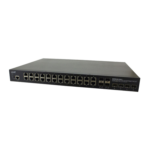
SISPM1040-xxxx-L3 Quick Start Guide
33854 Rev. A https://www.lantronix.com/ Page 3 of 4
Install the Switch: Note that if you must use the switch to connect outdoor devices such as outdoor IP
cameras with cable, then you must install an arrester on the cable between outdoor device and the switch.
Grounding: The switch has a grounding screw provided for grounding. Equipment
grounding is vital to ensure safe operation. The installer must ensure that the switch is
properly grounded during and after installation.
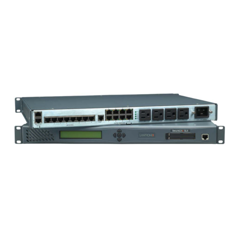
Mount the Switch in a 19-inch Rack: 1. Attach the mounting brackets to
both sides of the chassis. Insert screws and tighten then with a screwdriver to secure the brackets. 2. Place the
switch on a rack shelf in the rack. Push it in until the oval holes in the brackets align with the mounting holes in
the rack posts. 3. Attach the brackets to the posts. Insert screws and tighten them.
Mounting the Switch on Desk or Shelf: 1. Verify that the workbench is sturdy and reliably grounded.
2. Attach the four adhesive rubber feet to the bottom of the switch.
Installing SFP/SFP+ Modules: You can install or remove a mini-GBIC SFP/SFP+ module from an
SFP/SFP+ port without having to power off the switch. 1. Insert the module into the SFP/SFP+ port.
2. Press firmly to ensure that the module seats into the connector. Note: The SFP/SFP+ ports should use
UL Listed Optional Transceiver product, Rated 3.3Vdc, Laser Class 1. See the related SFP manual for details.
Installing DAC Cables: You can install or remove DAC-1m, DAC-2m, DAC-3m, and DAC-5m cables in ports
29-32. See the Install Guide for more information.
Connecting PDs: Note that this device does not comply with IEEE 802.3at at 48‐51.4 VDC. This device drops
~1.3V from Vin to PSEout. IEEE requires these PSEout voltages at the PSE output into the cable: 802.3af:
44VDC, 802.3at: 50VDC. Not meeting this PSEout requirement may cause power up failures or power cycling
with devices drawing maximum power with maximum cable loss.
Power can be from either of the two power sources (AC input or DC input) or site source DC. Note that DC
power is required for PoE operation.
Connecting to AC Power: 1. Connect the AC power cord to the AC power receptacle of switch. 2. Connect
the other end of the AC power cord to the AC power outlet. 3. Check the SYS LED. If it is ON, the power
connection is correct.
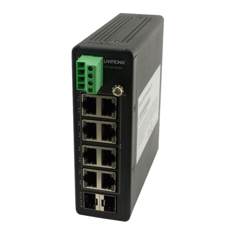
Connect the DC Power Wires:Warning: Connect the power supply to the
switch first, and then connect the power supply to power. Otherwise, catastrophic
product failure may occur. 1. Place an appropriate safety flag and lockout device
at the source power circuit breaker or place a piece of adhesive tape over the
circuit breaker handle to prevent accidental power restoration while you are
working on the circuit. 2. Insert the negative/positive DC wires into the V-/V+ DC
Power Input terminals, respectively. 3. Use a small flat-blade screwdriver to
tighten the wire-clamp screws on the front of the terminal block connector.
4. Check the SYS LED. If it is ON, the power connection is correct.
Power Disconnection: To disconnect power from the switch after it is powered on: 1. Turn off power to the
switch. 2. Disconnect the cables.
Connect the DI/DO Relay Wires: 1. Insert the negative (ground)/positive DI/DO Relay wires into the V-
/V+ DC Power Input terminals , respectively. 2. Use a small flat-blade screwdriver to tighten the wire-clamp
screws on the front of the terminal block connector.
Note: Digital output (relay): 24VDC/1A. Digital input: level 0 (Low) -> 0V to 6V,
level 1 (High) -> 10V to 24V.
FAULT: The two contacts of the terminal block connector are used to detect user-
configured events. The two wires attached to the fault contacts form an open
circuit when a user-configured event is triggered. If a user-configured event does
not occur, the fault circuit remains closed.
