Larius THOR Operating manual

OPERATING AND
MAINTENANCE INSTRUCTION
ENGLISH
OPERATING AND
MAINTENANCE INSTRUCTION
PAINT SPRAYING EQUIPMENT
Ed. 004 09 - 11

Due to a constant product improvement programme, the factory reserves the right to modify
technical details mentioned in this manual without prior notice.

1
THOR
English
INTRODUCTION .................................................. p.1
WARNINGS .......................................................... p.2
WORKING PRINCIPLE ........................................ p.3
TECHNICAL DATA ................................................ p.4
DESCRIPTION OF THE EQUIPMENT ................. p.5
Alarm messages .............................................. p.7
Functions table ................................................. p.7
Alarm message table ....................................... p.8
TRANSPORT AND UNPACKING ......................... p.8
SAFETY RULES ................................................... p.9
Electrical safety precautions ............................ p.10
SETTING-UP ........................................................ p.10
Connection of the flexible hose to the gun ....... p.10
Check on power supply .................................... p.10
Connection of the tooling to the power
supply ............................................................... p.12
Washing of the new equipment ........................ p.12
Preparing the product ...................................... p.13
WORKING ............................................................ p.14
Start of the working operations ........................ p.14
Spray adjustment ............................................. p.16
CLEANING AT THE END OF THE WORK ........... p.16
Cleaning for solvent-based products ................ p.16
Cleaning for water-based products .................. p.20
ROUTINE MAINTENANCE .................................. p.22
Check on the packing nut ................................. p.22
Checking the heat exchange radiator............... p.23
Checking the seal gasket (o-ring) .................... p.23
PROBLEMS AND SOLUTIONS ........................... p.24
CORRECT PROCEDURE OF
DECOMPRESSION .............................................. p.25
REPLACEMENT OF THE PUMPING
GROUP’S GASKETS ........................................... p.26
Pit stop maintenance........................................ p.27
Lower seal ........................................................ p.27
Upper seal ........................................................ p.29
SPARE PARTS
COMPLETE ELECTRO-MECHANICAL
UNIT ..................................................................... p.34
COMPLETE LONG PUMP UNIT .......................... p.36
SHORT PUMP UNIT FOR STANDARD
PRODUCTS ......................................................... p.38
SUCTION AND CIRCULATION UNIT FOR
STANDARD PRODUCTS ..................................... p.39
PRESSURE CONTROL DEVICE ......................... p.40
TROLLEY ............................................................. p.42
ELECTRICAL CONTROL .................................... p.43
ELECTRIC MOTOR .............................................. p.44
ACCESSORIES .................................................... p.45
VERSIONS ........................................................... p.50
ELECTRIC PISTON PUMP
WE ADVISE THE USE OF THIS EQUIPMENT ONLY BY PROFESSIONAL OPERATORS.
ONLY USE THIS MACHINE FOR USAGE SPECIFICALLY MENTIONED IN THIS MANUAL.
Thank you for choosing a LARIUS S.R.L. product.
As well as the product purchased,
you will receive a range of support services
enabling you to achieve the results desired,
quickly and professionally.
A
B
C
D
E
F
G
H
L
M
N
O
P
Q
R
S
T
U
V
ZI
W

2
THOR
English
Read this operator’s manual carefully before using the equipment.
An improper use of this machine can cause injuries to people or things.
Do not use this machine when under the influence of drugs or alcohol.
Do not modify the equipment under any circumstances.
Use products and solvents that are compatible with the various parts of the equipment, and read the manufacturer’s warnings care-
fully.
See the Technical Details for the equipment given in the Manual.
Check the equipment for worn parts once a day. If any worn parts are found, replace them using ONLY original spare parts.
Keep children and animals away from work area.
Comply with all safety standards.
It indicates an accident risk or serious damage to equipment if this warning is not followed.
It indicates important recommendations about disposal and recycling process of products in accordance with the environmental
regulations.
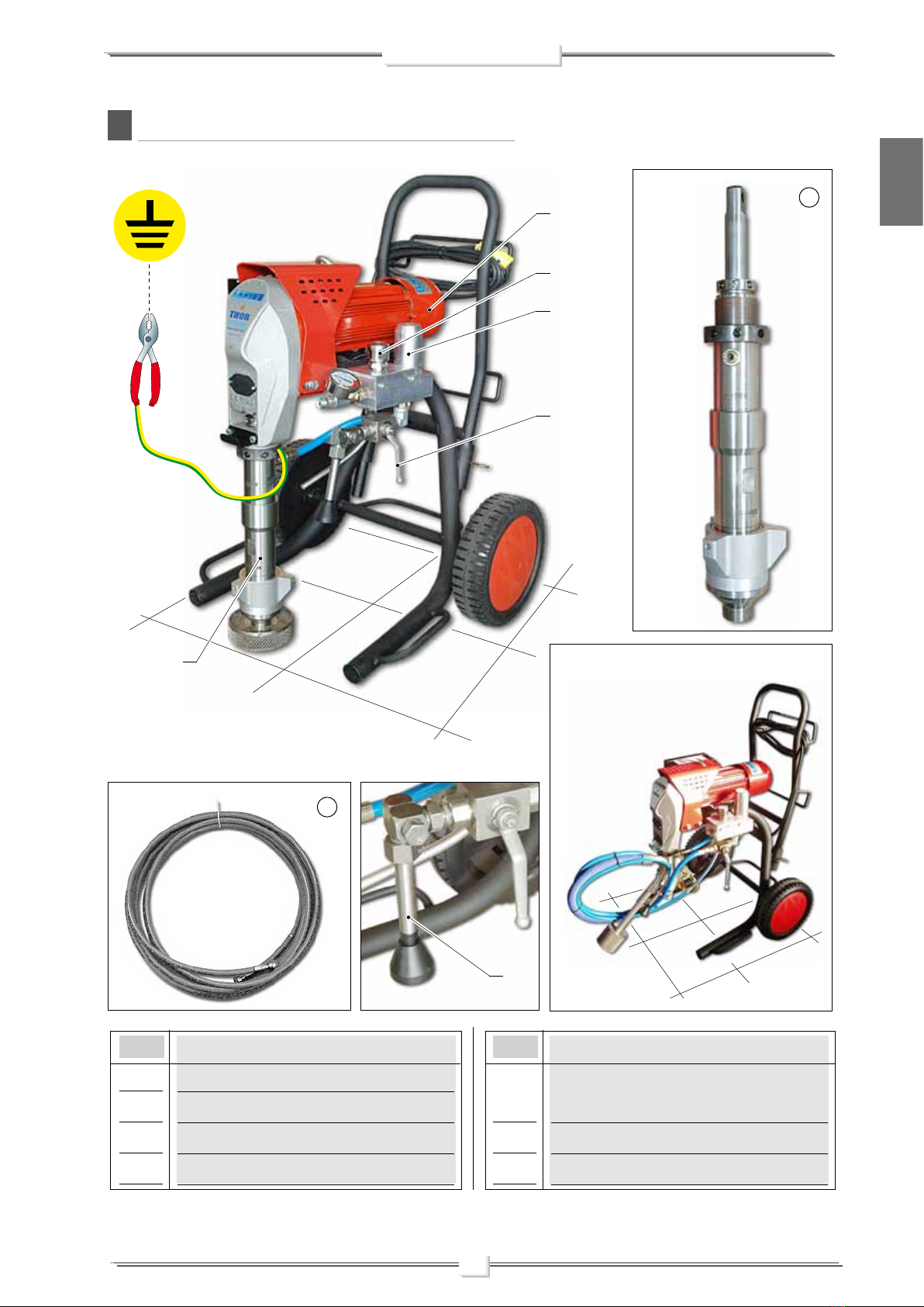
WARNINGS The table below provides the meaning of the symbols used in this manual in relation to using, earthing,
operating, maintaining, and repairing of this equipment.
It indicates a fire or explosion risk if this warning is not followed.
Eliminate all ignition sources such as pilot lights, cigarettes, portable electric lamps and plastic drop cloths.
Keep work area free of debris.
ONLY use this equipment in a well ventilated area.
EARTH ALL THE EQUIPMENT LOCATED IN THE WORK AREA.
Do not form connections or switch light switches on or off if the air contains inflammable fumes.
If electrical shocks or discharges are encountered the operation being carried out using the equipment must be stopped immedia-
tely.
Keep a fire extinguisher at hand in the immediate vicinity of the work area.
It indicates wound and finger squashing risk due to movable parts in the equipment.
Tenersi lontano dalle parti in movimento.
Do not use the equipment without the proper protection.
Before any inspection or maintenance of the equipment, carry out the decompression procedure explained in this manual, and prevent
any risk of the equipment starting unexpectedly.
Report any risk of chemical reaction or explosion if this warning has not been given.
There is a risk of injury or serious lesion related to contact with the jet from the spray gun. If this should occur, IMMEDIATELY contact
a doctor, indicating the type of product injected.
Do not spray before the guard has been placed over the nozzle and the trigger on the spray gun.
Do not put your fingers in the spray gun nozzle.
Once work has been completed, before carrying out any maintenance, complete the decompression procedure explained in this
manual.
Report any danger of electric shock if the warning and presence of live electrical parts has not been indicated.
Store in a dry place and do not expose to the rain.
Check that the cables are in good condition.
Switch off the equipment and discharge any electricity before cleaning or maintaining the equipment.
Mark any clamps attached to earth cables.
Use ONLY 3-wire extension cords and grounded electrical outlets.
Before starting work make sure that the electrical system is earthed and that it complies with safety standards.
It is obligatory to wear suitable clothing as gloves, goggles and face shield.
Wear clothing that complies with the safety standards in force in the country in which the equipment is used.
Do not wear bracelets, earrings, rings, chains, or anything else that may hinder the operator’s work.
Do not wear clothing with wide sleeves, scarves, ties, or any other piece of clothing that could get tangled up in moving parts of the
equipment during the work, inspection, or maintenance cycles.

3
THOR
English
A
Indoor
Outdoor
Industrial buildings
Industrial constructions
Redeveloping
Roofing
Fields of application
Plasters
Stucco paste
Fire retardants
Intumescents
Insulation coatings
Water proofing
Application materials
Testured acrylics and
elastomerics
Eifs and synthetic
Stucco finish coats
Deck coatings roofing
WORKING PRINCIPLE
The THOR unit is defined “electric piston pump”.
An electric piston pump is used for high pressure painting without
air (from this process derives the term ”airless”).
The pump is controlled by an electric motor coupled with a
reduction gear.
A cam shaft and a connecting rod allow to obtain the reciprocating
motion necessary to the working of the “pumping group” piston.
The piston movement produces a “vacuum”.
The product is sucked, pushed towards the pump outlet and then
sent to the gun through the flexible hose.
An electronic device located next to the reduction box, is used to
regulate and control the pressure of the material leaving the pump.
When the pump reaches the set value, the motor stops and starts
again when the value decreases.
A safety valve avoiding overpressure, guarantees the total reliability
of the equipment.

4
THOR
English
B
TECHNICAL DATA
*Available on request with special voltages
Parts of the pump in contact with the material Stainless Steel AISI 420B, Teflon; Aluminium
, Galvanised steel
THOR
SUPPLY (single-phase)*
RUN GENERATOR SUPPLY
(single-phase)
MOTOR POWER
MAX. WORKING PRESSURE
MAX. DELIVERY
MATERIAL OUTLET
WEIGHT
LEVEL OF THE SOUND PRESSURE
MINIMUM LENGTH
MINIMUM HEIGHT
MAXIMUM LENGTH
MAXIMUM HEIGHT
WIDTH
230V C.A. 50Hz
9 Kw asynchronous
2,8 kW
230 bar
7,5 L/min
M16 x 1,5 (M)
76 Kg
≤ 60dB(A)
(A) 700 mm
(B) 1000 mm
(C) 750 mm
(D) 1100 mm
720 mm
B
C
D
A

5
THOR
English
CDESCRIPTION OF THE EQUIPMENT
Version with short pumping unit
Connect hose
POS.
1
2
3
4
POS.
5
,
6
7
Electric motor
Pressure transmitter
Pumping group
Recirculation valve
Description
High pressure flexible pipe of compen-
sation Ø3/8”
Recirculation tube
Safety valve
Description
1
2
3
3
5
4
6
7

6
THOR
English
POS.
8
9
10
11
Suction filter
Pressure gauge
Airless manual gun L91X
Trigger safety clamp
Description POS.
12
13
14
15
Earth cable with clamp
Control equipment
ON/OFF switch
Flexible pipe connection
Description
1011
12
8
13
9
9
14
15
15 9

7
THOR
English
POS.
1
2
,
3
4
ON/OFF switch
Work pressure adjustment knob
,
Maximum pressure
Minimum pressure
Descrizione POS.
5
,
6
7
8
Material circulation and machine washing
position
Alarms
Message screen
Function keys
Descrizione
FUNCTIONS TABLE
Description of functionType of function
Function
symbol
P
J
Pd
c
h
Working pressure (bar)
Motor current (A)
Pressure setting (bar)
Dissipator temp. (°C)
Working hours (h)
Indicates the real time pressure used during the work cycle
Indicates the real time amperage on the equipment’s motor during the work cycle
Indicates the pressure set before the work cycle begins
Indicates the dissipator temperature (in degrees Centigrade) during the work cycle
Indicates the total number of hours the equipment has worked
ALARM MESSAGES
When the product to be applied is finished the pump “sucks air”
and automatically switches to the minimum number of cycles.
The alarm messages function is described on the area sign (6).
Each time key (8) is pushed, the messages are displayed on the
screen (7).
When an alarm message has been indicated the
machine has to be switched off and on again using
switch (1).
Each time the machine is switched off, the conden-
sers remain charged for about 5 minutes.
To avoid risk of shock, when removing the electrical
box wait until the condensers have discharged
altogether.
1
6
7
8
2
4
5
3

8
THOR
English
ALARM MESSAGE TABLE
CauseType of alarm
Alarm symbol
F1
F2
F3
F4
F5
F6
F7
F8
Maximum current
Dissipator temp.
Motor temp.
Maximum voltage
Minimum voltage
Earth connection
Pressure sensor missing
Automatic switch-off during circulation
phase (15 minutes)
The motor’s current absorption is too
high
The dissipator temperature is too high
The motor temperature is too high
The voltage is too high
The voltage is too low
The earth connection is disconnected
or non-existent
The pressure sensor is damaged or
not fitted
The equipment is in cleaning mode
Check the mechanical and hydraulic
condition of the equipment. If necessary,
take action
Check that the dissipator surfaces are
clean and that the dissipator is properly
ventilated
Check that the motor’s heat dissipation
surfaces are clean. Check that cooling
ventilation is correct
Check the connection to the electrical
line and reinstate the correct nominal
voltage
Check the connection to the electrical
line and reinstate the correct nominal
voltage
Check the earth cable and, if necessary,
replace it. Make sure that the machine
is earthed
Replace it
Wait until the equipment has stopped
completely before using it for a new job
Solution
DTRANSPORT AND UNPACKING
• The packed parts should be handled as indicated in the
symbols and markings on the outside of the packing.
• Before installing the equipment, ensure that the area to
be used is large enough for such purposes, is properly lit
and has a clean, smooth floor surface.
• Check the packing is undamaged on receipt of the equi-
pment. Unpack the machine and verify if there has been
any damage due to transportation.
In case of damage, call immediately LARIUS and the
Shipping Agent.
All the notices about possible damage or anomalies must
arrive timely within 8 days at least from the date of receipt
of the plant through Registered Letter to the Shipping
Agent and to LARIUS.
The user is responsible for the operations of unloa-
ding and handling and should use the maximum
care so as not to damage the individual parts or
injure anyone.
To perform the unloading operation, use only
qualified and trained personnel (truck and crane
operators, etc.) and also suitable hoisting equipment
for the weight of the installation or its parts. Follow
carefully all the safety rules.
The personnel must be equipped with the necessary
safety clothing.
The disposal of packaging materials is a customer’s
competence and must be performed in accordance
with the regulations in force in the country where
the plant is installed and used
.
It is nevertheless sound practice to recycle packa-
ging materials in an environment-friendly manner
as much as possible.
• The manufacturer will not be responsible for the unloading
operations and transport to the workplace of the machi-
ne
.

9
THOR
English
ESAFETY RULES
• THE EMPLOYER SHALL TRAIN ITS EMPLOYEES ABOUT
ALL THOSE RISKS STEMMING FROM ACCIDENTS, ABOUT
THE USE OF SAFETY DEVICES FOR THEIR OWN SAFETY
AND ABOUT THE GENERAL RULES FOR ACCIDENT
PREVENTION IN COMPLIANCE WITH INTERNATIONAL
REGULATIONS AND WITH THE LAWS OF THE COUNTRY
WHERE THE PLANT IS USED.
• THE BEHAVIOUR OF THE EMPLOYEES SHALL STRICTLY
COMPLY WITH THE ACCIDENT PREVENTION AND
ALSO ENVIRONMENTAL REGULATIONS IN FORCE IN
THE COUNTRY WHERE THE PLANT IS INSTALLED AND
USED.
• NEVER SPRAY OVER FLAMMABLE PRODUCTS OR SOL-
VENTS IN CLOSED PLACES.
• NEVER USE THE TOOLING IN PRESENCE OF POTEN-
TIALLY EXPLOSIVE GAS.
Read carefully and entirely the following instruc-
tions before using the product.
Please save these instructions in a safe place.
The unauthorised tampering/replacement of one
or more parts composing the machine, the use of
accessories, tools, expendable materials other than
those recommended by the manufacturer can be
a danger of accident.
The manufacturer will be relieved from tort and
criminal liability.
The high speed of travel of the product in the hose
can create static electricity through discharges
and sparks. It is suggested to earth the equipment.
The pump is earthed through the earth cable of
the supply.
The gun is earthed through the high pressure
flexible hose.
All the conductors near the work area must be
earthed.
Always check the product is compatible with the
materials composing the equipment (pump, spray
gun, flexible hose and accessories) with which it
can come into contact. Never use paints or sol-
vents containing halogen hydrocarbons (as the
methylene chloride).
If these products come into contact with aluminium
parts can provoke dangerous chemical reactions
with risk of corrosion and explosion.
• KEEP YOUR WORK PLACE CLEAN AND TIDY. DISORDER
WHERE YOU ARE WORKING CREATES A POTENTIAL RISK
OF ACCIDENTS.
• ALWAYS KEEP PROPER BALANCE AVOIDING UNUSUAL
STANCE.
• BEFORE USING THE TOOL, ENSURE THERE ARE NOT
DAMAGED PARTS AND THE MACHINE CAN WORK PRO-
PERLY.
• ALWAYS FOLLOW THE INSTRUCTIONS ABOUT SAFETY
AND THE REGULATIONS IN FORCE.
• KEEP THOSE WHO ARE NOT RESPONSIBLE FOR THE
EQUIPMENT OUT OF THE WORK AREA..
• NEVER EXCEED THE MAXIMUM WORKING PRESSURE
INDICATED.
• NEVER POINT THE SPRAY GUN AT YOURSELVES OR
AT OTHER PEOPLE. THE CONTACT WITH THE CASTING
CAN CAUSE SERIOUS INJURIES. IN CASE OF INJURIES
CAUSED BY THE GUN CASTING, SEEK IMMEDIATE MEDI-
CAL ADVICE SPECIFYING THE TYPE OF THE PRODUCT
INJECTED. NEVER UNDERVALUE A WOUND CAUSED BY
THE INJECTION OF A FLUID.
• ALWAYS DISCONNECT THE SUPPLY AND RELEASE THE
PRESSURE IN THE CIRCUIT BEFORE PERFORMING ANY
CHECK OR PART REPLACEMENT OF THE EQUIPMENT.
• NEVER MODIFY ANY PART IN THE EQUIPMENT. CHECK
REGULARLY THE COMPONENTS OF THE SYSTEM. RE-
PLACE THE PARTS DAMAGED OR WORN.
• TIGHTEN AND CHECK ALL THE FITTINGS FOR CONNEC-
TION BETWEEN PUMP, FLEXIBLE HOSE AND SPRAY GUN
BEFORE USING THE EQUIPMENT.
• ALWAYS USE THE FLEXIBLE HOSE SUPPLIED WITH
STANDARD KIT. THE USE OF ANY ACCESSORIES OR
TOOLING OTHER THAN THOSE RECOMMENDED IN
THIS MANUAL, MAY CAUSE DAMAGE OR INJURE THE
OPERATOR.
• THE FLUID CONTAINED IN THE FLEXIBLE HOSE CAN
BE VERY DANGEROUS. HANDLE THE FLEXIBLE HOSE
CAREFULLY. DO NOT PULL THE FLEXIBLE HOSE TO
MOVE THE EQUIPMENT. NEVER USE A DAMAGED OR A
REPAIRED FLEXIBLE HOSE.

10
THOR
English
CHECK ON POWER SUPPLY
Electrical safety precautions
• Check the switch is on the "OFF" position before connecting
the cable to the mains
.
• Never carry a plugged-in equipment.
• Disconnect the equipment before storing it and before
performing any maintenance operation or replacing of ac-
cessories.
• Do not carry the equipment neither unplug it by pulling the
electric cable.
• Protect the cable from heat, oil and sharp edges.
• When the tool is used outdoors, use only an extension cable
suited for outdoor use and so marked.
• Take care when the pumping rod is moving.
Stop the machine whenever someone is within its vicinity.
• Repairs of the electrical equipment should only be carried
out by skilled personnel, otherwise considerable danger to
the user may result.
• Check the mains voltage corresponds to the equipment’s
rating.
IF THE PRODUCT TO BE USED IS TOXIC, AVOID
INHALATION AND CONTACT BY USING PROTEC-
TION GLOVES, GOGGLES AND PROPER FACE
SHIELDS.
TAKE PROPER SAFETY MEASURES FOR THE
PROTECTION OF HEARING IN CASE OF WORK
NEAR THE PLANT.
Never attempt to tamper with the calibre of in-
struments.
Make sure that the electrical system is earthed and
complies with regulations.
FSETTING-UP
CONNECTION OF THE FLEXIBLE HOSE TO THE GUN
• Connect the high pressure flexible hose
(F1)
to the pump
(F2)
and to the gun
(F3)
, ensuring to tighten the fittings (the
use of two wrenches is suggested)
.
NEVER use sealants on fittings’ threads
.
It is ADVISED to mount a high pressure manometer at the
pump outlet (see on page “Accessories”) to read the product
pressure
.
• It is recommended to use the hose provided with the standard
kit (ref.18036).
NEVER use a damaged or a repaired flexible hose.
F2
F1
F3

11
THOR
English
THOR
MADE IN ITALY
WWW.LARIUS.COM
Code Serial
number
Year
PRESSIONE MASSIMA 230 bar
MAX PRESSURE 3335 PSI
20705 1006
230Vac 50Hz 2.8Kw
THOR equipment is fitted with an additional external earth cable
that is connected to the stem on the pump unit be means of a
specific clamp (F4), in order to protect the operator against any
risk of static or electric shock.
Should anyone use an extension cable between
the tooling and the socket, it must have the same
characteristics as the cable supplied (minimum
diameter of the wire 4 mm2) with a maximum len-
gth of 50 mt. Higher lengths and lower diameters
can provoke excessive voltage falls and also an
anomalous working of the equipment.
• The supply cable is provided without plug.
Use a plug which guarantees the plant earthing.
Only a technician or a skilled person should perform the
connection of the plug to the electric cable.
To avoid electric shock when disassembling or checking the
electronic equipment, wait 5 minutes after having disconnected the
power supply cable, so that the electricity stored in the condensers
while working can be dissipated.
Also check the condition of the earth cable to avoid any risk of
shock.
Before carrying out any checks on the machine
(maintenance, cleaning, or replacing parts) switch
off the machine and wait until it has stopped
altogether.
While checking stay away from electrical or mo-
ving parts to avoid any risk of shock or crushing
of hands.
WARNING :
• DO NOT modify the plug for the earth socket
in any way.
• ONLY use electrical connections that are
earthed.
• Make sure that any earth extension cords are
in good condition.
• ONLY use three-core extension cables.
• Avoid direct contact with the rain. Keep the
equipment in a dry place.
F4
Voltage

12
THOR
English
Before connection up the power supply to the
equipment, make sure that the electrical system
is earthed and complies with regulations.
Make sure that the clamp (F4) provided is positioned
correctly, in order to earth the pump unit in the
equipment properly.
• Ensure the gun (F3) is without nozzle.
• Press the switch (F5) of the equipment “ON” (I).
CONNECTION OF THE TOOLING TO THE POWER SUPPLY
• Check the switch (F5) is on the "OFF" (0) position before
connecting the cable to the mains.
• Place the pressure control knob (F6) on the “MIN” position
(turn counterclockwise).
WASHING OF THE NEW EQUIPMENT
• The equipment has already been adjusted at our factory with
light mineral oil left inside the pumping group as protection.
Therefore, wash with diluent before sucking the product.
• Lift the suction unit and immerse it in the bucket that contains
the washing liquid.
• Connect the clamp to an earthing point.
F5
F6
OFF
F3
F5
ON

13
THOR
English
MIN MAX
• Turn the pressure setting knob (F6) clockwise to the “CIR-
CULATION & WASHING” position (drop symbol).
• Point the spray gun into the collection container (F7) and hold
the trigger down (in order to expel the oil contained) until clean
liquid flows out.
Now, release the trigger.
• Remove the suction hose and remove the bucket of cleaning
liquid.
• Now point the spray gun (F8) into the container (F7) and press
the trigger to recover any cleaning liquid left.
• As the pump idles, press the “OFF” (0) switch (F5) to stop
the tooling.
When this is complete, release the trigger.
Use a metal container (F7).
To avoid any risk of electric shock connect the
collection container to a surface that is earthed
(e.g. concrete) and not to surfaces that will insulate
the container from the earth.
Hold the spray gun against the edge of the metal
contained (F7).
Absolutely avoid to spray solvents indoors. In
addition, it is recommended to keep away from
the pump in order to avoid the contact between
the solvent fumes and the electric motor.
For disposing of the washing liquid, see the re-
quirements laid down in the Standards in force in
the country in which the equipment is used and
act accordingly.
The Client is solely responsible for any irregular
action taken before, during, or after disposing of
washing liquid, or in interpreting and applying the
current Standards in this regard.
• Now the machine is ready.
When water-based paint has been used, in addition to washing
using the cleaning liquid, we recommend washing with soapy
water and then clean water.
PREPARING THE PRODUCT
• Mix and filter the product before using it.
MAKE SURE THE PRODUCT IS SUITABLE TO BE
USED WITH AN AIRLESS SPRAY GUN.
Make sure the product to be used is compatible
with the materials employed for manufacturing the
equipment (stainless steel and aluminium).
Because of that, please contact the supplier of the
product
.
F6
Circulation
and washing
F7
F8

14
THOR
English
REMOVE THE FILTER (F9) FOR DENSE PRO-
DUCTS.
Never use products containing halogen hydrocarbons (as methylene
chloride). If these products come into contact with aluminium parts
of the equipment, can provoke dangerous chemical reactions with
risk of explosion.
G
• Use the tooling after performing all the SETTING UP ope-
rations above described.
WORKING
START OF THE WORKING OPERATIONS
Make sure that the electrical system is earthed and
complies with regulations.
Make sure that the earth clamp is positioned cor-
rectly to ensure a safe earth on the pump unit.
• Dip the suction pipe (G1) into the product tank.
Version with flexible hose (G2)
G1
G2
NO
F9

15
THOR
English
MIN MAX
• Turn the pressure setting knob (G5) clockwise to the “CIR-
CULATION & WASHING” position (drop symbol).
• Press the switch (G4) “ON” (I) of the equipment.
• Open the recycling tap (G3).
• Make sure that the product circulates through the circulation
hose (G6).
• Close the circulation tap (G3).
• The machine continues to suck up product until it has filled the
hose as far as the spray gun, after which it will automatically
stop when the set pressure is reached.
Closed
G3
Open
G3
ON
G4
G5
G6
Circulation
and washing

16
THOR
English
SPRAY ADJUSTMENT
• Slowly turn clockwise the pressure control knob (G5) to reach
the pressure value in order to ensure a good atomization of
the product.
The valve (G6) serves two purposes:
• Safety: It opens the passage at pressure peaks exceeding
280-300 bar;
• Regulation: It returns the working pressure to 250 bar and
levels out the hydraulic operating hysteresis.
Safety valve: when working at the maximum pres-
sure available, releasing the gun trigger sudden
increases of pressure can occur. In this case, the
safety valve (G6) opens automatically eliminating
part of the product from the recirculating tube
(G7).
Then it closes so as to go back to the first working
conditions.
• An irregular and marked spray on the sides indicates a low
working pressure. On the contrary, a too high pressure causes
a high fog (“overspray”) and waste of product.
• In order to avoid overthickness of paint, let the gun advance
sideways (right-left) when spraying.
• Always paint with regular parallel bands coats.
• Keep a safety and constant distance between the gun and the
support to be painted and also keep yourselves perpendicular
to it.
NEVER point the spray gun at yourselves or at
other people. The contact with the casting can
cause serious injuries.
In case of injuries caused by the gun casting, seek
immediate medical advice specifying the type of
the product injected.
HCLEANING AT THE END
OF THE WORK
Make sure that the electrical system is earthed and
complies with regulations.
CLEANING FOR SOLVENT-BASED PRODUCTS
G5
G7
G6

17
THOR
English
• Reduce pressure to the minimum (turn counterclockwise the
pressure control knob (H1)).
• Press the switch (H2) placed on the box of the electric motor,
to stop the equipment.
• Hold the spray gun trigger down.
• Open the circulation tap (H3) to discharge the pressure in
the circuit.
• Lift the suction hose and replace the bucket containing the
product with a bucket of cleaning liquid (make sure it is
compatible with the product you are using).
• Unscrew the nozzle on the spray gun (remember to clean it
with cleaning liquid).
• Press the switch (H2) “ON” (I) of the equipment.
H1
H2
OFF
ON
H2
Open
H3

18
THOR
English
MIN MAX
• Turn the pressure setting knob (H1) clockwise to the “CIR-
CULATION & WASHING” position (drop symbol).
• Close the circulation tap (H3).
• Point the spray gun (H4) into the container (H5) used to
collect the cleaning liquid and hold the trigger down to expel
any product remaining, until clean liquid flows out.
Now, release the trigger.
Use a metal container (H5).
To avoid any risk of electric shock connect the
collection container to a surface that is earthed
(e.g. concrete) and not to surfaces that will insulate
the container from the earth.
Hold the spray gun against the edge of the metal
contained (H5).
• Make sure that the product circulates through the circulation
hose.
Make sure that the machine sucks in clean washing
liquid. Allow the cleaning liquid to discharge into
another container and do not mix it with the cleaning
liquid still to be used.
We recommend circulating the cleaning liquid for
at least 15 minutes.
For disposing of the washing liquid, see the re-
quirements laid down in the Standards in force in
the country in which the equipment is used and
act accordingly.
The Client is solely responsible for any irregular
action taken before, during, or after disposing of
washing liquid, or in interpreting and applying the
current Standards in this regard.
H1
Closed
H3
Circulation
and washing
H5
H4
Table of contents
Other Larius Paint Sprayer manuals

Larius
Larius K-2 Operating manual

Larius
Larius PLA K11421 User manual

Larius
Larius Excalibur Liner Operating manual

Larius
Larius Zeus Operating manual

Larius
Larius TORNADO 2 Series Manual

Larius
Larius MIST-LESS 09 Manual

Larius
Larius ZEFIRO Operating manual

Larius
Larius Pegaso Manual

Larius
Larius L400 Series User manual

Larius
Larius DALI Manual