Larry vs Harry Bullitt User manual

Bullitt Assembly Manual
2018

Before you start
= Important / pay attention!
Crank/BB tool Pliers
TorxAllen/Hex key
Grease Screwdriver Chainring
Nut Wrench
Wrenches
3 4 5 6 25 10 13 15 17 19
mmmmmmmmmm
Phillips
mm 8
mm T
mmmmmm
Hollowtech 2
bottom bracket
tool (68mm bsa)
and Preload key
Tools required
x2
x2
Note: Only use torque specs if
not listed on hardware.
Some steps contain links to full
manuals in the bottom of the
page.
If you watch the Assembly Video
you can pay attention to these
numbers, that shows you how it
should be done.
To avoid scratches to frame,
leave as much wrapping on until
you need to remove it!
Grease
Grease sensitive parts (metal on
metal).
Look out for the grease icon
which will appear throughout
the manual.
King Harry says:
Don’t worry!
I’ll walk you through this!!
1.0

5
4
3
2
Step 1 Installing Front Fork & Headset
1
Apply grease to the bearing cups, the crown race
and internal threads of the fork.
Drop the lower bearing on the crown race of the fork
with the angle facing up. Slide the fork through the head
tube. Place the upper bearing into the top cup cap?
with angle facing down.
5
mm 19
mm
Components
Top cap
top view
Front Fork
Headset
1
2
Place the compression ring and top cover in the
correct order.
Thread the top cap into the steer tube of the fork
carefully with your fingers so you don’t cross the threads!
Tighten top cap to adjust the headset bearing tension
(3-4 Nm) with a chamferless 6 point 19mm socket or
19mm cone wrench (FIG. A.1)
Tighten the 5mm hex bolt (3 - 4Nm) in the top cap to
lock the threads into place (FIG. A.2)
1.0
1.1
1.0
1.1
Tools
5
1
2
3
4
5
3 4
5
Be sure the cone shaped
expander in the top cap is released
3-5 mm before installation
A.1
1
2
A.2
FIG. A

3
mm
Step 2 Installing Steering Rod, Headset and Easy-Up
5
mm
4
mm
3
4
5
6
1
B.1
2
B.2
FIG. A
FIG. B
1
2
Steering Rod
Easy-Up
Headset
Loosen the headset adjustment ring on the Easy-Up (1)
and tighten the adapter sleeve bolt (in the bottom) with
5mm hex (6Nm) (2)
Apply grease to bearing cups and crown race.
Install Bearings and Steering Rod: Place lower bearing
into the lower cup and snap the dust seal in properly.
Slide Steering Rod through frame from below and
support the bottom of it (so it doesn’t fall out).
Drop upper bearing into the top cup , place
compression ring and top cover in the correct
order, followed by the spacer
Place the Easy-Up all the way into the Steering Rod
(by tapping it downward gently) and tighten 2x4mm
hex clamp bolts (5-6 Nm) (FIG. A)
Tighten the headset bearings with the adjustment ring
by turning clockwise by hand. (FIG. B.1)
Secure the adjustment ring by tightening the 3mm hex
fixing bolt. (3 Nm) (FIG. B.2).
Tighten Quick Release (QR) clamp.
2.0 2.1
2.2
1
3
4 5
6
2
Components
Tools
6
2
3
4
5
1
2.0
2.1
2.2

5
mm
Step 3 Mounting Dropouts
L R
Drop outs
Chainring
Nut Wrench
Grease mounting surface on frame Tighten hex bolts 3x 5mm from the outside of the
frame and hold the nuts in place with the Chainring
Nut Wrench, torque to (14-17 Nm) (FIG. A)
Components
Tools
1
1
3.0
3.0
FIG. A

Step 4 Installing Mudguards & Front Reflectors
5
mm 10
mm
4
mm
4
3
mm
mm
Grease bolts.
Install Front Mudguard (3 Nm) and Front Reflector
Install Rear Mudguard (3 Nm)
If installing Gates Belt, leave the Rear Stays unmounted
until after the Gates installation.
Re-adjust tire gap after wheel is on and inflated.
x1 x1x2
Components
Tools
Rear Mudguard
x1x2
Front Mudguard
Front reflector
4.0
4.0
1x
3x 5
mm
1x
4
mm
2x
3
mm
1
1
2
2

Step 5 Mount Wheels
15
mm
15
mm
25
T
10
mm
10
mm
Rear Wheel
Front Wheel
Grease axels and centerlock rotor splines.
Check rotor centerlock (40 Nm) and rotor bolts T25
(4 Nm), cassette lockring (40 Nm) and spoke tension.
For wheels with nuts, tighten (30-45 Nm).
Wheels with QR, make sure lever is fully secure.
Inflate tires and adjust Mudguards.
Remember if installing Gates Belt: Wait with installation
of Rear Mudguard Stays untill Gates Belt is installed.
Components
Tools
5.0
(Only needed
for pedal brake)
2x
5.0
Crank/
BB tool

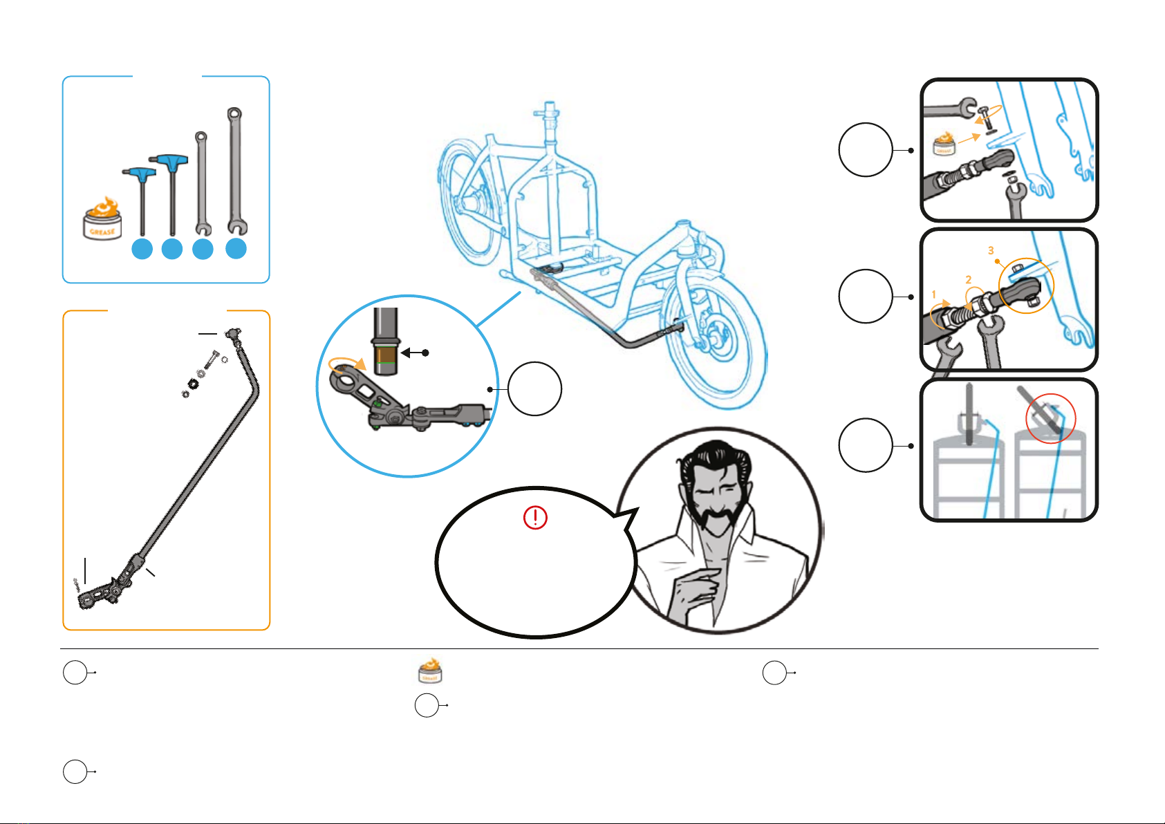
Step 6 Mount Steering Arm
17
mm
13
mm
x2
x2
Steering Arm
Clamp on
in this area
45
mmmm
Steering
rod clamp
Length and angle
adjustment clamp
Ball joint
Attach clamp at the end of steering arm to the steering
rod, by sliding the clamp all the way up until it touches
the underside of the crown race. Lightly tighten bolts.
(FIG. A) (Later tighten completely to adjust the alignment
between handlebar and front wheel).
Torque the clamp to the steering rod 2x 5mm (7-9Nm).
Bolt the ball joint underneath the fork tab (11-14Nm).
Grease the bolt and make sure the washers and
shims are in the correct order.
Tighten the 17mm nuts at the ball joint, starting with the
rear one (6.2.1),repeat for the front (15-18 Nm) or until
star washers are locked (6.2.2)
Align ball joint to fork tab, so it moves smoothly through
the steering cycle (without unlocking star washers) (6.2.3)
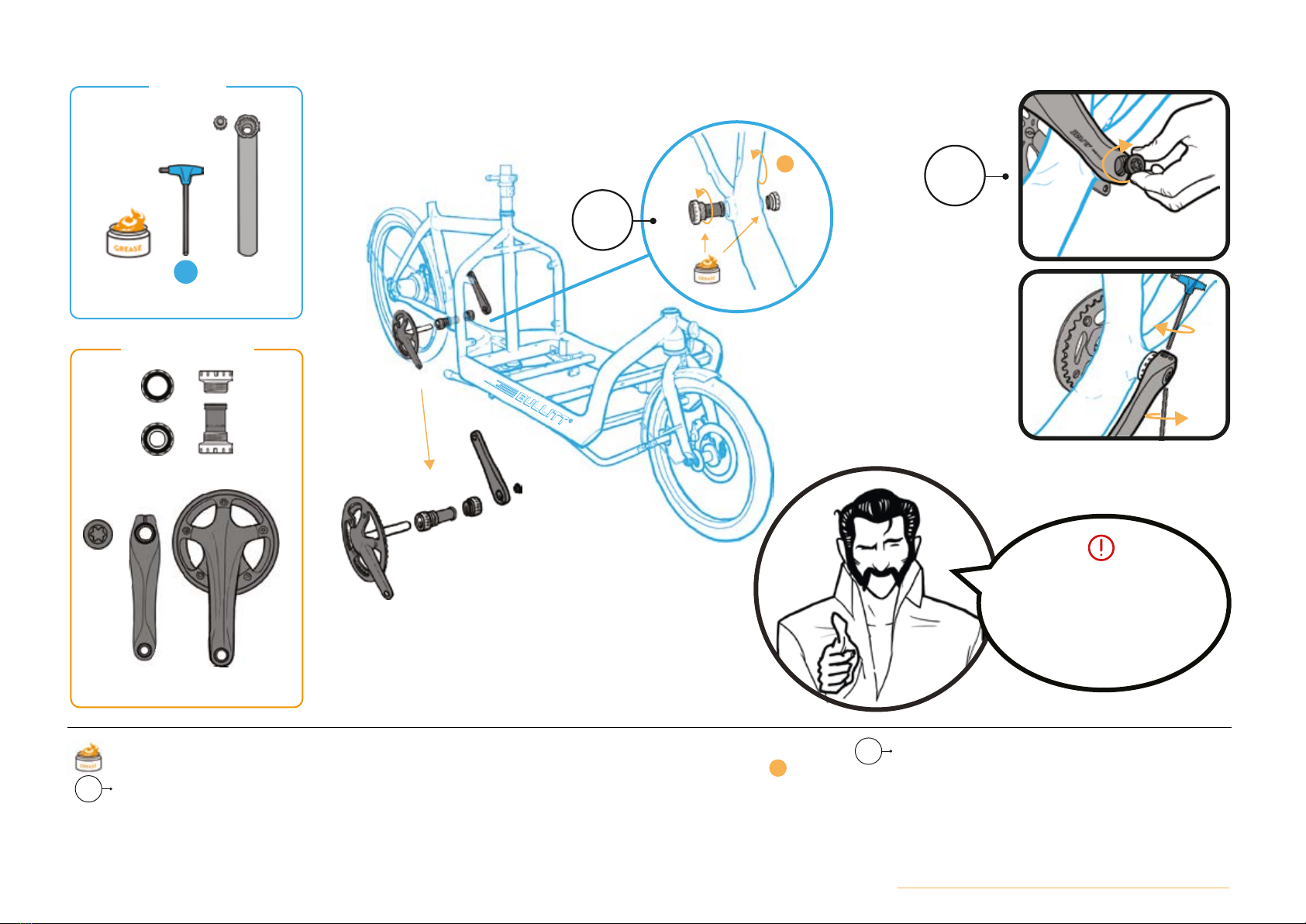
Adjust Steering Rod length and angle at the clamp with 2x
4mm hex bolts (so the tire doesn’t rub arm or oversteer
when handlebar is turned all the way left or right)
Tighten bolts (5Nm). Adjust alignment between
handlebar and front wheel so the bike rides straight.
Fully torque the steering arm clamp to the steering rod
2x 5mm hex bolts (7-9Nm).
Be patient and check that the
steering arm doesn’t contact the corner
of the frame (2cm gap) or kickstand,
when it is up also.
Components
Tools
6.0
6.1
6.2
6.3
6.0
6.1
6.2
6.3
ALIGN
1
2
3

Step 7 Install Bottom Bracket & Crankset
Bottom Bracket
Crankset
FIG. B
FIG. C
Install Bottom Bracket:
Thoroughly grease threads.
Turn each cup in with your fingers, make sure they are
on their corresponding side and started correctly so you
don’t cross the threads!
Drive side (right side) tighten counter-clockwise.
Non-drive side (left side) tighten clockwise.
Use BB-tool to fully torque (35-50 Nm).
Mount the Crankset: Start with right crank arm,
(the one with chainring and axle attached), slide axle
through Bottom Bracket and attach left crank arm to it,
tightening the preload bolt with the preload-key
(0.7-1.5Nm) (FIG. B)
Install stopper plate and tighten the x2 (5mm)
hex-bolts (12-14 Nm) (FIG. C)
Components
Tools
5
mm Crank/BB tool
Before you begin, inspect frame to check
bottom bracket for damaged threads/paint, etc.
If needed, use the correct amount of BB
Spacers corresponding to your
specific crank
See the full Bracket and Crankset manual from Shimano here
1
1
7.0
7.1
7.0
7.1

Step 8 Mount Pedals
6
mm
15
mm
R
L
L
RDriveside tightens clockwise
Non-driveside tightens
counter-clockwise
Pedals
R
To mount the Pedals, thoroughly grease the threads
and start by turning each pedal in with your fingers,
making sure they are on their corresponding side
and started correctly so you don’t cross the threads!
Afterwards torque to (40 Nm) with pedal wrench or
6mm hex. (FIG. A & B)
Components
Tools FIG. A
FIG. B
L
Remember to put grease on the pedal
threads. The pedals is marked with L or R
so you know which side they fit.
Do not force the pedals into
the crank arms!
8.0

x2
Step 9 Install Gates Belt or Chain
Check or install Gates Frame block
Chain or Gates Belt
Gates frame block
Chain
Install Chain, check length and quick link.
To adjust tension, use adjuster screws on Dropouts.
Check Gates frame block 2x 5mm hex bolts. (14 -
17Nm) (FIG. A)
Gates Belt
Remove frame block to slip belt into rear triangle.
Install belt, tension and alignment to Gates Carbon Drive
Specification. See the full manual from Gates here
Mount frame block 2x 5mm hex bolts. (14 - 17Nm) (FIG. A)
To adjust tension, use adjuster screws on Dropouts.
Components
Tools FIG. A
5
mm
Make sure to
check/tighten bolts even/also
when using chain.
9.0
1
1

Step 10 Mount Cockpit, Brakes, Shifter cable and -routing
Handlebar
Stem
Brakes
Shifter/cable
Bell
Align in 4th. gear
Mount Cockpit: Take o rubber top cap/plug, mount
stem with the shim aligned so it is level with the top of
the stem . Tighten bolts 2x4mm (6 Nm) and install
rubber top cap/plug again .
Cable routing: Start at handlebar, cross the hoses/cables
in a way that looks clean and functions when Easy-Up is
raised. Rear Brake and Shift Cable comes from the
right side of handlebar and Front Brake Cable from left.
Mount cables loosely with zip ties, tighten zip ties when
calipers are mounted and brake hoses are not kinked!
(See Cable Routing)
Mount Brake Calipers: Tighten adapter bolts (6-8 Nm).
Center brake calipers and tighten caliper bolts (6 Nm)
(FIG. A & B)
Install Shift Cable: Shift to lowest or highest gear on
shifter (cable fully released). Bring cable around to
cassette joint pulley, (inner cable fixing nut facing
outside toward the fork end), and slide the flat part of
the inner cable fixing washer into gap in the pulley.
Pass inner cable through slit in cassette joint bracket, insert
end of outer casing securely into outer casing holder.
The two yellow marks should be aligned in 4th gear on
Alfine 8.
Use barrel adjuster on shifter to fine adjust the gears
with fingers. (FIG. C)
Components
Tools
5
mm
25
T
4
mm Pliers
TOP VIEW
Align shim with slit
Front Brake
Shifter
Rear Brake
Side ViewSide View
Side View
Bottom View
Bottom View
Use zip ties to attach brake cables
Cable Routing
10.0
10.1
10.0
10.1
10.2
10.3
1
2
1
2
FIG. A FIG. B FIG. C
10.2 10.3

Step 11 Mount Seatpost, Clamp and Rear Reflector
Saddle, Seatpost, QR Clamp
Rear Reflector
Phillips
5
mm
Mount Rear Reflector to seatpost towards the upper
portion of the seatpost so that it can be lowered all the
way without interference.
Grease seat tube
Insert seatpost to minimum insert line. Adjust and tighten
QR Clamp.
Check saddle angle and tighten bolts 2x 5mm to (3Nm)
Components
Tools
1
11.0
11.0
2

8
mm
Step 12 Check Kickstand or Install (only RÅ)
Phillips
Tools
Torque kickstand bolts 2x 8mm to (23-27 Nm)
to each side of the frame.
Finish by tightening 2x bumpers (Phillips)
Installing kickstand on RÅ:
Set kickstand in place, start 8mm bolt by hand.
Tighten 2x (8mm) to each side of the frame (23-27 Nm).
Finish by tightening 2x bumpers (Phillips) (FIG. A)
FIG. A
12.0
12.0

Step 13 Test Ride!
And now... you are ready to test your Bullitt!
We hope you’ll enjoy the ride and take care out there!
Before you go on that sweet test ride - Check for
rattles, steering alignment, brake and gear adjustment.
Check ALL clamp bolts
before test ride.
13.0
13.0
This manual suits for next models
1
Table of contents
Other Larry vs Harry Bicycle manuals

Larry vs Harry
Larry vs Harry Twin Seat User manual

Larry vs Harry
Larry vs Harry Damper User manual

Larry vs Harry
Larry vs Harry Shimano Steps E-Bullitt 6100 User manual

Larry vs Harry
Larry vs Harry eBullitt EP8 User manual

Larry vs Harry
Larry vs Harry eBullitt E6100 User manual

Larry vs Harry
Larry vs Harry eBullitt User manual

Larry vs Harry
Larry vs Harry Shimano Steps E-Bullitt User manual