5
Instruction Manual
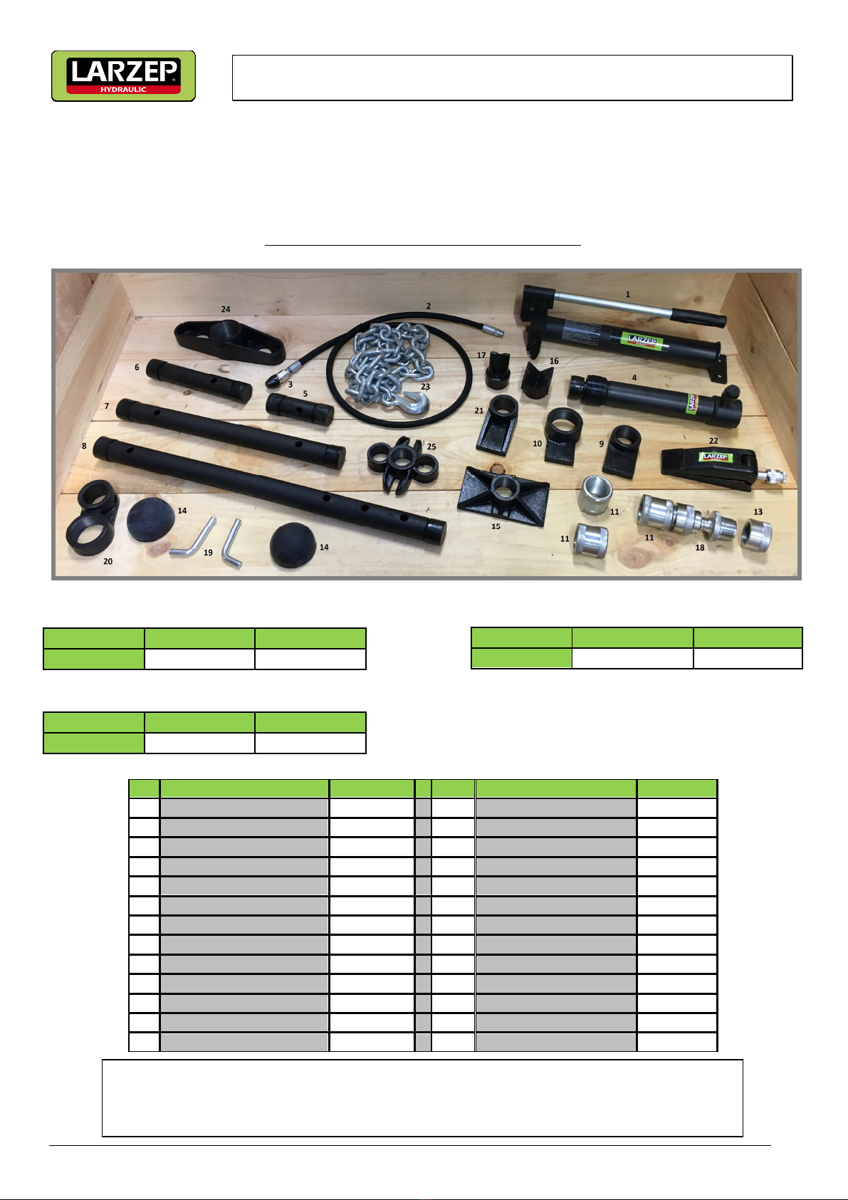
Maintenance Set
3. START UP
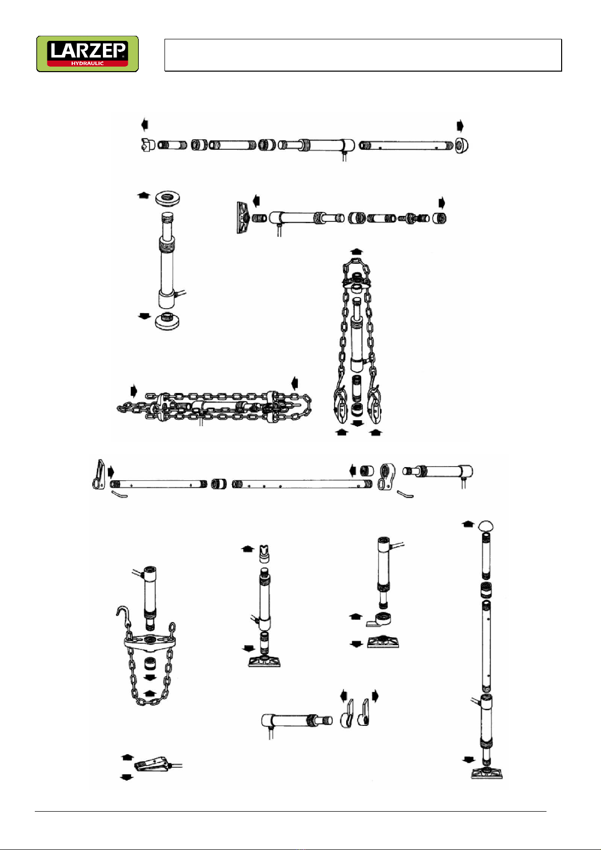
This equipment works by fitting different components to the cylinder or piston, which is activated by the pump. The pump also
moves the spreader cylinder. Do not use any other accessories than those supplied in the set.
The pump can be used in horizontal or vertical position with the head facing down. It is connected to the cylinder with a hose.
To do this, remove the cap at front of the pump and screw the hose end into the port using a sealer. The connection between
the hose and the cylinder is with a quick connector, male and female. Tighten the nut correctly to guarantee a leak-free
connection. The hose must not be twisted or kinked. Do not place objects on it and do not move the equipment pulling the
hose.
Before using the equipment, bleed the hydraulic circuit to remove the air from the valve system. To do this, open the discharge
tap turning it anticlockwise and action the lever several times. Then close the discharge tap turning it clockwise. The equipment
is now ready to use.
It is necessary to know the characteristics of the bodywork damage to select the accessories to be used. Action the pump
smoothly to avoid problems caused by e cessive pressure.
Always be aware of the working pressure using a pressure gauge fitted to the pump.
When the work is finished, pack all the components into the bo .
4. MAINTENANCE
Maintenance and repair work on this equipment should only be carried out by qualified personnel, with training and e perience
with the hydraulic systems used in this equipment.
Any maintenance operation will be carried out with the system depressurised. Regularly clean and lubricate the shafts and
moving parts of the equipment, which must always be clean and protected from e treme conditions.
Only original spare parts must be used.
Before using the set again, check that there are no bent, broken, cracked or loose components. If any anomaly is detected, do
not use the maintenance set; place it in a safe and clean place, where children or operators cannot access, until the equipment
be repaired.
When necessary, change the pump oil with the cylinder piston completely retracted. Remove the filler cap and empty the used
oil into a container. Then fill the pump with clean oil and avoid dirty entering the system when filling.
After a long period of intensive use it is recommended to change the oil to prolong the service life oi the equipment. Be careful,
an e cessive amount of oil can impede the functioning of the hydraulic system.
Use hydraulic oil type HL 01 HM with an ISO cinematic viscosity grade of 30 cST at 40°, or an Engler viscosity or 3 at 50°C. Never
use brake fluid.
When the equipment is not in use, the cylinder piston should be fully retracted to avoid corrosion. We recommend applying an
anti-rust agent to the piston.
Store the equipment in a dry place.
When the service life or the equipment is over, remove the oil and follow the local regulations to scrap it.
5. WARRANTY
LARZEP, S.A. guarantees its products against all design and manufacturing defects for the durations of two years from the date
of purchase. This guarantee does not include the ordinary wear of both metal and non-metal parts, abuse, using the equipment
beyond its rated capacity and any wear or damage incurred as a result of using a hydraulic fluid which is not recommended by
LARZEP, S.A.
Please note that if the equipment is disassembled or serviced by anyone other than an authorized service dealer or by LARZEP,
S.A., this guarantee is rendered null and void.
In the event of a warranty claim, return the equipment, to LARZEP, S.A. or the authorized dealer which sold you the hydraulic
equipment, LARZEP, S.A. will repair or replace the faulty equipment, whichever is deemed most appropriate. LARZEP, S.A. shall
not be held liable for any consequential damages or losses, which may occur as a result of faulty equipment