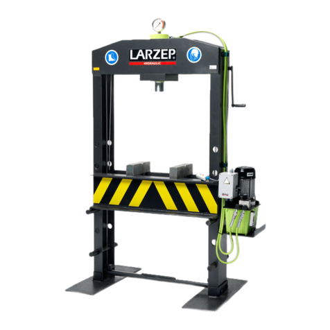
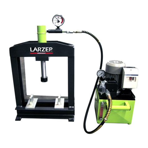
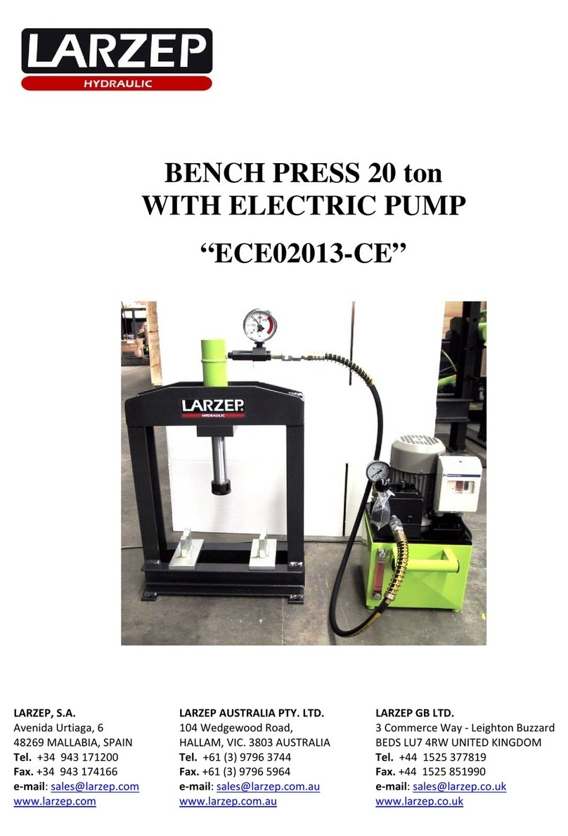
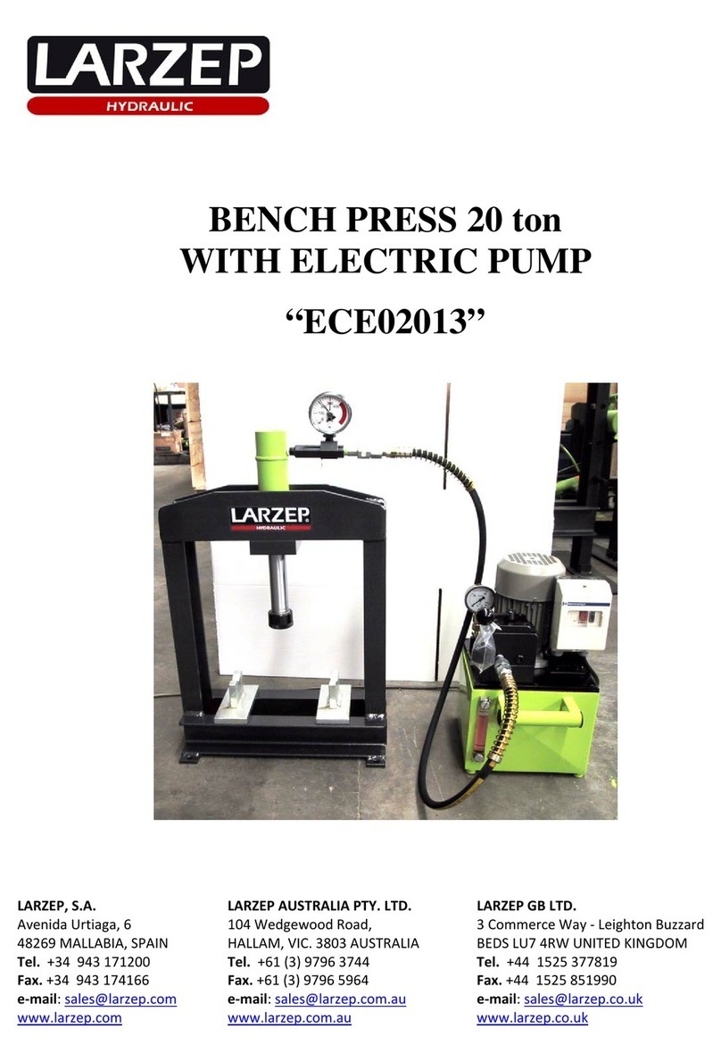
Larzep ECE01113 User manual

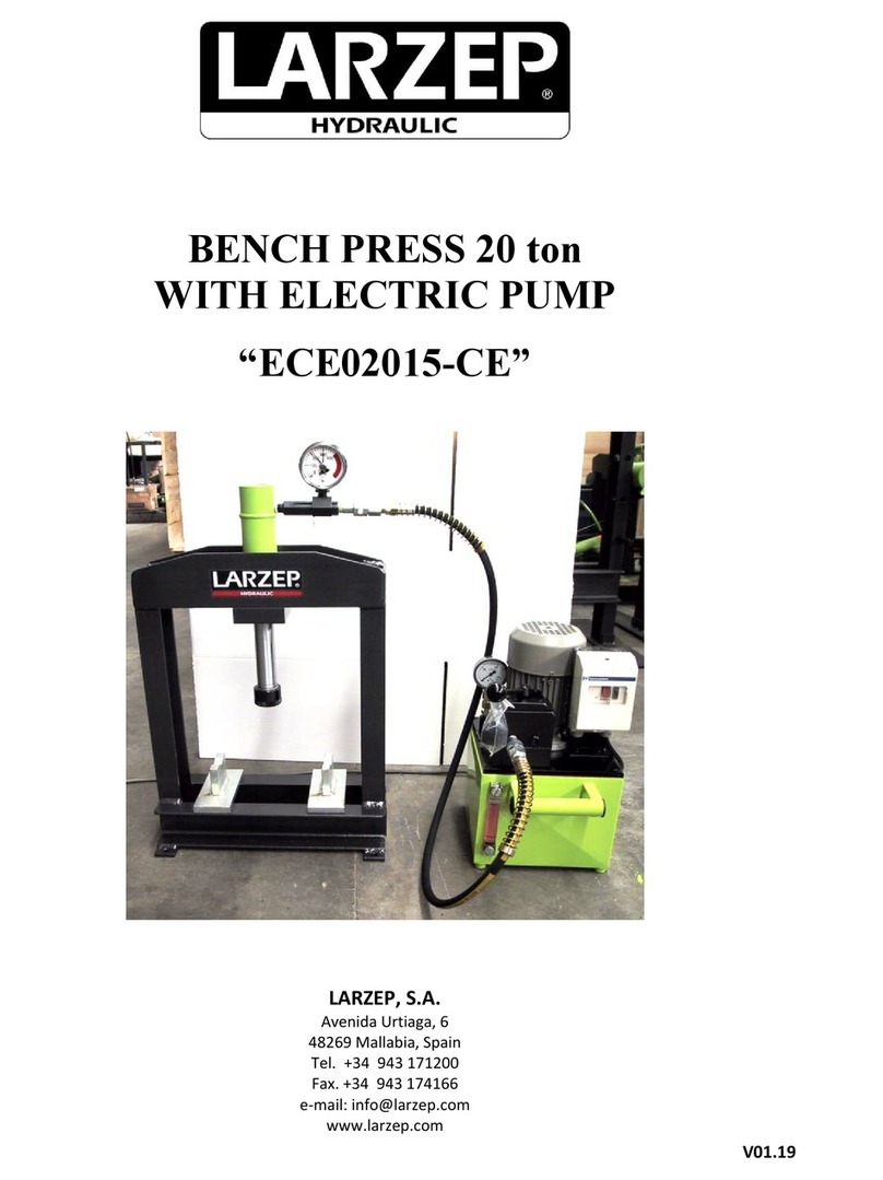
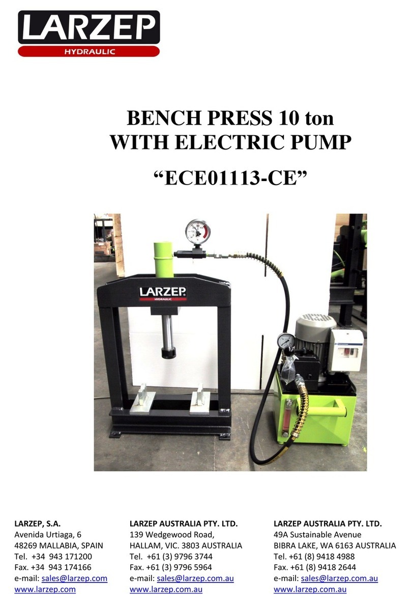
BENCH PRESS 10 ton
WITH ELECTRIC PUMP
“ECE01113”
LARZEP, S.A. LARZEP AUSTRALIA PTY. LTD. LARZEP GB LTD.
Avenida Urtiaga, 6 104 Wesgewood Road, 3 Commerce Way - Leighton Buzzard
48269 MALLABIA, SPAIN HALLAM, VIC. 3803 AUSTRALIA BEDS LU7 4RW UNITED KINGDOM
Tel. +34 943 171200 Tel. +61 (3) 9796 3744 Tel. +44 1525 377819
Fax. +34 943 174166 Fax. +61 (3) 9796 5964 Fax. +44 1525 851990
e-mail: [email protected]m e-mail: sales@larzep.com.au e-mail: sal[email protected].uk
www.larzep.com www.larzep.com.au www.larzep.co.uk

2
Instruction Manual
Bench Press with Electric Pump “ECE01113”
INDEX
1. BEFORE USING THE EQUIPMENT........................2
2. TECHNICAL FEATURES..........................................3
3. ESSENTIAL SAFETY REQUIREMENTS ...............4
3.1 GENERAL CONSIDERATIONS.
3.2 COMMANDS SECURITY.
3.3 PROTECTION DEVICES AGAINST MECHANICALL RISKS.
3.4 PROTECTION DEVICES AGAINST OTHERS RISKS.
3.5 SECURITY IN MAINTENANCE.
3.6 INDICATIONS.
4. TRANSPORT AND INSTALLATION.......................4-5
4.1 START UP
5. MAINTENANCE AND DAMAGES...........................5-6
6. WARRANTY.................................................................6
7. DECLARATION OF CONFORMITY.......................7
ANNEX
GENERAL DRAWING
1. BEFORE USING THE EQUIPMENT.
Before unpacking check for:
1. Oil leaks.
2. Signs of corrosion.
3. Damages in the hydraulic cylinder and the hydraulic line.
4. Damage sin the frames and accessories of the cylinder.
5. Damaged screws or connections.
6. Bad connection of the accessories.
If any anomaly it is detected, avoid the use of it and place it in a safe and far location until be repaired by an authorized service dealer.
Familiarize the operators with the equipment before using it, and read and follow the instructions and recommendations included in the packaging.
Any improper use, do not observed in this manual, and the omission of the same, may cause personal injuries and material damages which LARZEP, S.A. will not be
responsible.
Do not work with the equipment near of the flames, explosives, warm intense sources, or any other source which may produce fire, or which may produce damages
in the equipment. The hydraulic equipment must not be exposed to temperatures greatest than 60ºC, as on use as on storage.
When a place to the press is located, make sure that there is in a stable surface, is to say, that all base of the press, be supported. If any doubts exist about this
question, it is recommended that distribute the weight in a bigger area, placing a steel shell behind the press’s base.
Store the press when the piston is fully retracted. It is recommended protecting the cylinder with a plastic, or place the press in a clean area, for not damaging the
components and for keeping the press correctly storage.
2. TECHNICAL FEATURES.
HYDRAULIC CYLINDER
MODEL
KC01113
Push capacity (ton)
10 ton
Maximum pressure (Kg/cm)
700 Kg/cm
Stroke (mm)
130 mm
Effective area (cm)
15.9 cm
Oil capacity (cm³)
214.7 cm³
Approach speed (mm/sg)
31 mm/sg
Working advance speed (mm/sg)
5.8 mm/sg
If you are purchasing a cylinder or pump, for the use of it in the press, make sure that you are using a correct combination before assembling it.
We recommended, asking for advice in this questions to our technicians.
Never use equipment suspected to be in poor conditions.
Do not loose the instruction manual.
Never locate the press or store in a place where the children could access to it.

3
Instruction Manual
Bench Press with Electric Pump “ECE01113”
HYDRAULIC MOTORPUMP. REF: HAM7224
MODEL
HAM7224
Tank capacity
5 Litros útiles.
Volume in low pressure. Approaching
4 Litros/min
Volume in high pressure. Working.
0.36 Litros /min
Maximum pressure.
700 Kg/cm
Control valve
Manual Aluminio: 3 vías, 3 posiciones.
Motor
0, 75 kW a Tensión: 400V. 50Hz.3ph.
FRAME: MECHANICAL-WELDED
MODEL
ECE01113
Working height (mm)
352 mm
Working width (mm)
350 mm
Weight (Kg)
75 Kg
DESCRIPTION POWERPACK HAM7224 (See the figure).
The motor pump has the following part:
3. ESSENTIAL SAFETY REQUIREMENTS.
3.1 GENERAL CONSIDERATIONS
DANGEROUS AREA
The speed of the hydraulic cylinder during its extension is less than 30 mm/second. Therefore then machine should be considered by the application of ANNEX V of
the Declaration of CE Conformity.
Operators standing in the dangerous area around the machine should protect their feet, faces and hands from metal pieces being ejected during pressing.
Feet protection Face protection Hands protection
Used materials and components are not dangerous for the health and safety of operators. The hand pump contains LARZEP hydraulic oil ISO: HV46.
3.2 COMANDS
The cylinder advances when we act over the powerpack, push the general swicht (1-0) of the electrical cabinet or circuit motor breaker box.
To stop the motor we must push the red button.
We have to check the sense of the motor turn, it must be the same as the narrow labelled in the motor protector, if it does not coincide swap two cables between in
the terminal.
The hose connection is made; if not, the manual distributor valve have two outlets for the connection. The outlet labelled with “A” is the one to connect, the other
outlet labelled with “X” must be corking.
The operating of the distributor valve: If we act over the valve and we put it in “A” position, the cylinder will advance. When we put the valve in “T” position, the
cylinder will return and finally when the valve is in “C” position the pressure will be maintained.
Metal tank with oil level.
Metal lid, support for the entire hydraulic circuit.
Electric motor with corresponding coupling.
Hydraulic piston pump with filter.
Transportation plug and ventilation plug (plastic bag).
Pressure meter connection.
Motor circuit breaker box.
Manual distributing valve with 3/8 NPT outputs.
Internal safety valve adjusted to 700 bar.
Adjustable external pressure regulating valve: 0-700 bar.
Due to the FUNCTIONAL REASONS it is considered to be the space between the columns, the bed and the hydraulic cylinder piston.
Due to the MATERIAL PRESSED it is supposed to be surrounding area to the machine in case of metal parts being ejected during pressing.
HIDRAULIC OIL IS TOXIC IF IT ENTERS THE BLOODS STREAM. NEVER PLACE A FINGER OVER ANY ORIFICE OR LEAK,
WHICH COULD BE PRESSURIZED, SUCH AS THE HYDRAULIC LINE, AS THIS COULD CAUSE OIL TO BE INJECTED INTO BLOOD
STREAM.

4
Instruction Manual
Bench Press with Electric Pump “ECE01113”
3.3 SAFETY PREVENTIVE ACTIONS AGAINST MECHANICAL RISKS
The construction of machine has been calculated to bear without any breaking under conditions of foreseen utilization and for the whole life of the machine. The
hydraulic components have been designed and calculated in compliance with the ANSI B30.1, and have been proved to 875Kg/cmof pressing.
The frame of the machine does not cause to be dangerous in that sense.
3.4 SAFETY PREVENTIVE ACTIONS AGAINST OTHER RISKS.
The machine is provided with a thermal relay to protect the motor.
The hydraulic pump is equipped with an internal security valve in the tank, out of operator’s control and rated at 700 Kg/cm. The hydraulic cylinder is also furnisher
with a pressure relief valve, rated at 700 Kg/ cm, which could be rated by the operator from 0 to 700 Kg/cm.
3.5 MAINTENANCE
All the maintenance operations must be performed while the machine is stopped, thus avoiding this way any potentially dangerous situation. A poor maintenance
program of the press does not increase the risk, but obviously will revert in a lower performance.
The hydraulic pump is mounted out of the frame and access is very easy. To disassemble the pump unscrews the bolts in the tap cover. In order to disassemble the
cylinder it is required first to disassemble the piping and the cylinder from the frame.
ISOLATION OF POWER SUPPLY.
Release the cables of the terminal to disconnect the current tap of electrical energy, previously disconnect the pin from the network.
3.6 INDICATIONS
INFORMATION DEVICES
In the pump: Oil level, oil filling tap, pressure relief valve, additional gauge port.
In the cylinder: A gauge in order to know the operating pressure anytime.
The press, the cylinder and the pump have their corresponding serial numbers marked on them. In addition to it, you can find a sticker label showing the commercial
reference, capacity, working pressure, name and address of the manufacturer.
4. TRANSPORT AND INSTALLATION.
The machine is delivered properly packed in a wooden ballet. For it’s handling, it is recommended to use a forklift truck or a crane. In the last case, it is necessary to
make the slings trespass the arc of the frame. When doing this operation, you should be cautious and prevent the flexible hoses and couplings from any damage.
HYDRAULIC CONNECTION
Unscrew the rapid coupler site in the cylinder, and connect the hose, screwing the rapid coupler to the limit with the hand.
SUBSTITUTION OF THE TRANSPORT PLUG
Replace the plug of the transport located in the cover of the tank by the pressurized plug given with the press. (Plastic stock marked in the handle of the distributing
valve).
INSTALLING THE GAUGE
1-Replace the threaded tap in the top of the cylinder by the gauge, which is supplied separately.
2-Tighten the gauge cone to the gauge adaptor seat by using a flan wrench size 22.
3-Hold the gauge screen by hand during threading process and after reaching a comfortable reading position set the gauge screen free so that it turns the last quarter
solidarily with the thread.
4- The power pack is also provided with a gauge adaptor, with thread 3/8” BSP.
ELECTRIC CONNECTION
1- Connect the binding post to the network
2- See the voltage, it must be 380 V
3- Assure that the valve is in neutral position; it is to say “C” position.
4- Put the general selector in (1) position. The motor starts.
5- Check that the motor goes in the sense labelled with and arrow in the motor. In opposite case, change the position of two cables between themselves in the
terminal and try again. This operation must be done with the equipment disconnected.
6- Connect again the equipment and check the function.
CHECKING THE RIGHT OPERATION OF ALL DEVICES AND MECHANISM
1. Select the working maximum pressure.
2. Start the motor.
3. Check that the cylinder’s piston advance.
4. Check that the cylinder’s piston returns pushing by an internal spring. In both cases act over the valve as explained in previous point.
5. With no material in the press, repeat the movement of advance, reaching the end of the stroke of the cylinder. In this moment the pressure will go
increasing, so the gauge will read the pressure. This pressure will go increasing until reach the maximum pressure of the installation, previously
chosen. The cylinder maintains the reached pressure and the gauge the pressure reading.
6. Check that there are not oil leaks.
7. Act over the valve and return the piston. It returns by the internal spring. The return could be slower in the end of the return stroke.
8. Put the material to be treated in the press.
9. Once the operation is finished, push the red button to stop the motor.
10. Put the general selector in (0) position,
The machine is stable enough to operate without fixing, but if is placed in an area commonly operated by mobile machinery (cranes,
lifting equipment…) it is strongly recommended to fix it to the desired place by drilling the supporting plates.
5
Instruction Manual
Bench Press with Electric Pump “ECE01113”
4.1 START UP
Connect the machine as described in the previous point.
The maximum pressure that the hydraulic equipment develops is 700 Kg/cm.
The machine is provided with an external limiter valve rated on factory at 700 Kg/cm.
In the cover of the power pack is located the pressure regulation screw.
Release the lock nut and go tightening or releasing the screw, go checking with the gauge, and once that the wished pressure is reached; tighten the lock nut to avoid
that the vibration may decontrol the system.
5. MAINTENANCE.
The hydraulic circuit of the press is closed, so in normal conditions no oil leakage should be coming up.
In case of oil leakage, after the proper repairing work, you should fill up the tank with hydraulic oil by LARZEP (Ref. AZ8901); the pump is equipped with an oil
level indicator to control the need quantity of oil.
As far as a non-continuous use of the press is concerned (1 hour per day), oil replacement should be done once a year.
To empty the tank, you should remove the cover and take the oil out to another container. Please, bear in mind the existing rules for waste processing when handling
the used oil.
Keep greasy and lubricated the pin bearings, the piston and in general all the parts that might be in friction.
USE ONLY LARZEP HYDRAULIC OIL
Other grades of oils or types of hydraulic fluid (such as brake fluid) may affect the performance of the equipment or cause the deterioration of the seals.
Always use the original LARZEP parts to prolong the service life of your hydraulic equipment. LARZEP S.A. or your authorized dealer can supply you with
original parts for simple maintenance work.
PROBLEMS
POSSIBLE FAILLURES
SOLUTION
1. The piston does not advance.
- Primeless pump.
1. Feed the pump keeping it started some minutes.
- Dirty accumulated in the filter.
2. Extract and clean it.
-No oil in the reservoir.
3. Check the level.
- Cylinder pressure retainer damaged.
4. Replace the retainer.
-Directional valve damaged.
5. Replace the valve.
- Cylinders body damaged.
6. Repair the body of the cylinder.
- Pneumatic problem.
7.Check the installation.
2. The cylinder does not reach pressures.
- Pressure relief valve unrated.
8. Rate the valve.
- Cylinder pressure retainer damaged.
See Solution. 4.
- Cylinders body damaged.
See Solution. 6.
3. The cylinder does not maintain pressure.
- Cylinder pressure retainer damaged.
See Solution. 4.
- Directional valve damaged.
See Solution. 5.
4. The cylinder does not retract.
- Damaged return spring.
9. Replace the spring.
- Directional valve damaged.
See Solution. 5.
The solutions marked in black must be carried out by specialized personnel, for it, go to an authorized distributor that sold you the equipment or to LARZEP, S.A.,
we have original spare part kits as well as the necessary personnel, do not doubt in contacting to us, we are to yours disposition.
Always use original spare parts LARZEP, you will extend the life utility of the equipment, in opposite case the company will not become person in charge of the
possible failures, damages or losses that take place.
6. WARRANTY.
LARZEP, S.A. guarantees its products against all design and manufacturing defects for the durations of two years from the date of purchase. This guarantee does not
include the ordinary wear of both metal and non-metal parts, abuse, using the equipment beyond its rated capacity and any wear or damage incurred as a result of
using a hydraulic fluid which is not recommended by LARZEP, S.A.
Please note that if the equipment is disassembled or serviced by anyone other than an authorized service dealer or by LARZEP, S.A., this guarantee is rendered null
and void.
In the event of a warranty claim, return the equipment, to LARZEP, S.A. or the authorized dealer which sold you the hydraulic equipment, LARZEP, S.A. will
repair or replace the faulty equipment, whichever is deemed most appropriate. LARZEP, S.A. shall not be held liable for any consequential damages or losses,
which may occur as a result of faulty equipment
DO NO ATTEMPT TO FILL THE PUMP WITH OIL WHILE IT IS CONNECTED TO A CYLINDER WHICH IS SUSTAINING A LOAD
BECAUSE IT MAY OVERPRESSURIZE THE RESERVOIR WHEN THE PISTON RETRACS AND CAUSE DAMAGE OR INJURY

6
Instruction Manual
Bench Press with Electric Pump “ECE01113”
7. DECLARATION OF CONFORMITY.

7
Instruction Manual
Bench Press with Electric Pump “ECE01113”

8
Instruction Manual
Bench Press with Electric Pump “ECE01113”
Table of contents
Other Larzep Power Tools manuals

Larzep
Larzep EE03116 User manual

Larzep
Larzep EE12018-CE User manual

Larzep
Larzep EE12018 User manual

Larzep
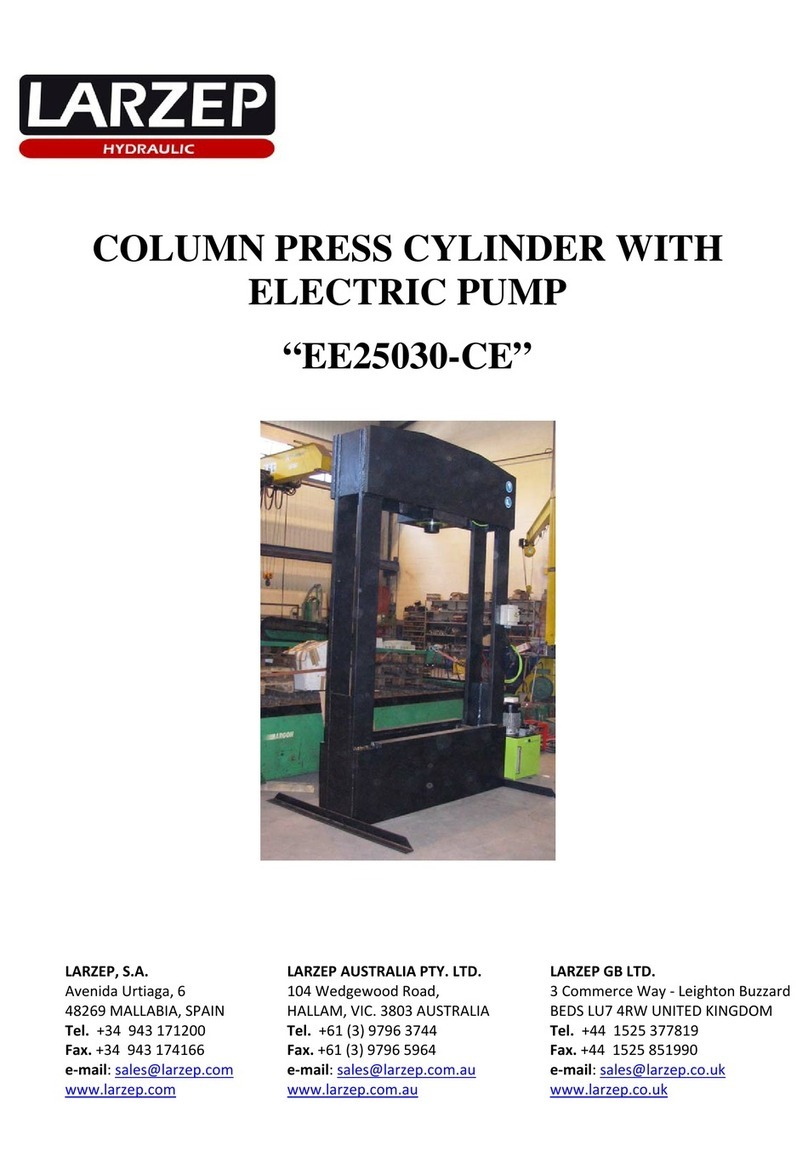
Larzep EE25030-CE/L User manual

Larzep
Larzep CA1014 User manual

Larzep
Larzep EM06018 User manual

Larzep
Larzep EE06018-CE User manual

Larzep
Larzep EE06018 User manual

Larzep
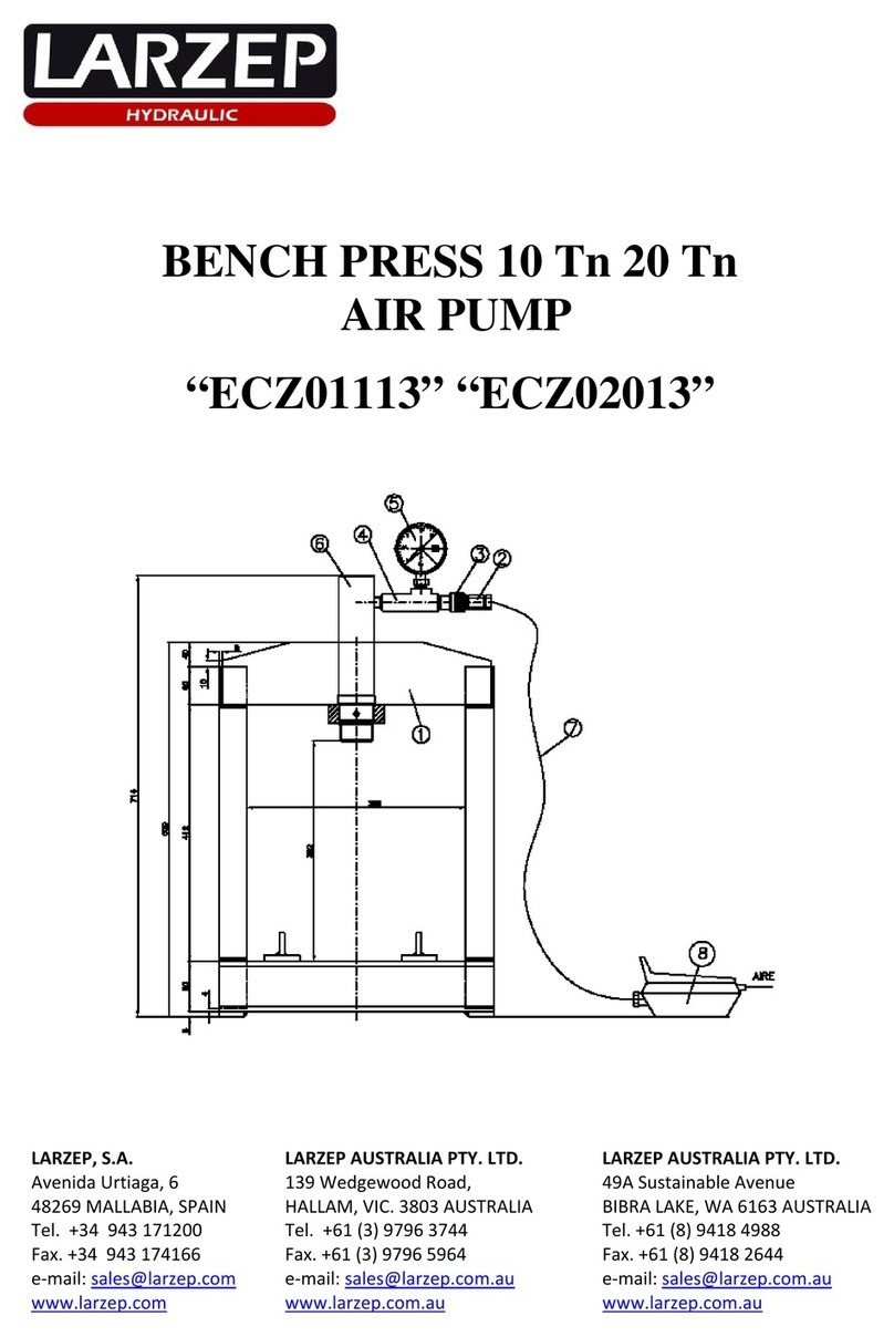
Larzep ECZ01113 User manual

Larzep
Larzep EE03116-CE User manual

Larzep
Larzep ECE02013 User manual

Larzep
Larzep ECE02015-CE User manual

Larzep
Larzep ECE01113-CE User manual

Larzep
Larzep EZ03012 User manual

Larzep
Larzep ECE01115 User manual

Larzep
Larzep EE25030-CE User manual

Larzep
Larzep ECM01113 User manual

Larzep
Larzep EM03012 User manual

Larzep
Larzep ECE02013-CE User manual