Larzep EZ03012 User manual

COLUMN PRESS WITH
HYDROPNEUMATIC PUMP
“EZ03015”
LARZEP,S.A.
AvenidaUrtiaga,6
48269Mallabia,Spain
Tel.+34943171200
Fax.+34943174166
e‐mail:[email protected]
www.larzep.com

2
INSTRUCTIONMANUAL
ColumnPresswithHydropneumaticPump"EZ03015"
INDEX
1- ESSENTIAL SAFETY REQUIREMENTS ---------------------------------------- 2-3
2- TECHNICAL FEATURES --------------------------------------------------------------- 3
3- TRANSPORT AND ERECTION -------------------------------------------------------- 4
4- START-UP OF THE MACHINE -------------------------------------------------------- 4
5- MAINTENANCE ------------------------------------------------------------------------ 4-5
6- WARRANTY -------------------------------------------------------------------------------- 5
7- DECLARATION OF CONFORMITY ------------------------------------------------- 6
ANNEX
GENERAL DRAWING
1. ESSENTIAL SAFETY REQUIREMENTS
GENERAL CONSIDERATIONS
Description
Safety Principles
The speed of the hydraulic cylinder during its extension is less than 30 mm/second. Therefore, the machine should be considered by the application of ANNEX V
of the Declaration of CE Conformity.
Operators standing in the dangerous area around the machine should protect their faces and feet form metal pieces being ejected during pressing.
Face Protection Feet Protection
Used materials and components are not for the health and safety of operators. The electric pump contains hydraulic oil type ISO: HV46
The machine is delivered in a wooden pallet and fixed to it in order to he handled by means of a forklift truck or a crane. Once the machine is unpacked, it can be
handled by using a crane and slings trespassing the arc formed by the columns and the head.
COMMANDS
The cylinder is pushed when we operate the hydro-pneumatic foot.
The pump pedal has three positions; pull, push and locking.
For the working of the cylinder we must connect the pump to the air net at a pressure of 6 bar
In order to stop the pushing of the cylinder the pedal must be operated or the pump must be disconnected from the compressed air net.
For re-start of the machine, that device that device should be unlocked and the start button should be pressed.
Failure in the energy feed.
The machine stops.
SAFETY PREVENTIVE ACTIONS AGAINST MECHANICAL RISKS
The construction of machine has been calculated to bear without any breaking under conditions of foreseen utilization and for the whole life of the
machine.
The hydraulic components have been designed and calculated in compliance with the ANSI B30.1 and have been tested at 875 kg/cm² pressure.
It is operator's responsibility to wear special protective clothes and attachments in both feet and face to prevent any damage as a result of accidental
fallings and breakings of metal pieces under operation or machine components in touch with.
Risks due to surfaces, bends and angles: The frame of the machine does not cause to be dangerous in that sense.
Due to the functional reasons, "dangerous area" is considered to be the space between the columns, the bed and the hydraulic cylinder piston.
Due to the material pressed, "dangerous area" is supposed to be the surrounding area to the machine in case of metal parts being ejected
during pressing.
The machine is equipped with supporting plates in the columns for a perfect stability. The machine gets operated without fixing onto the floor,
but it is strongly recommended to do it by drilling the plates in the place of your choice.

3
INSTRUCTIONMANUAL
ColumnPresswithHydropneumaticPump"EZ03015"
SAFETY PREVENTIVE ACTIONS AGAINST OTHER RISKS
Risk due to power supply: The machine is provided with a protective device for the pump protection.
Risk due to hydraulic power: The hydraulic pump is equipped with an internal security valve in the tank, out of operator's control and rated at 700
Kgr/cm².
MAINTENANCE
All the maintenance operations must be performed while the machine is stopped, thus avoiding this way any potentially dangerous situation.
A poor maintenance program of the press does not increase the risk, but obviously will revert in a lower performance.
The hydraulic pump is mounted in the frame and access is very easy. To disassemble the pump, unscrew the bolts in the tap cover. In order to
disassemble the cylinder, it is required to first disassemble the piping.
Isolation of the power supply: Release the terminal wiring to disconnect the power supply.
The machine is designed to assure that all maintenance tasks are performed by the operator in an easy and safe way. All the components that would
require any maintenance operation are easily accessible.
INDICATIONS
Information Devices
In the pump:
Cup of oil filling.
Pressure relief valve.
Additional gauge intake.
Oil level.
The press, the cylinder and the electric pump have their corresponding serial numbers marked on them. In addition to it, you can find a sticker label showing the
commercial reference, capacity, working pressure, name and address of the manufacturer.
Warning signals
Obligation to protect the face.
Obligation to protect the feet.
Risk of electric current.
Read the operation manual before using.
2. TECHNICAL FEATURES
HYDRAULIC CYLINDER SM03015
MODEL SM03015
Max. Pushin
g
Capacit
y
Tn. 30,92
Working Pressure kg/cm2 700
Hydraulic Stroke mm 150
Effective area cm2 44.1
Oil capacit
y
cm2 663
Extens. speed, without load mm/sg 30
Extension speed at 700 k
g
/
cm2 0.6
HYDRAULIC PUMP REF. Z12107
Oil tank capacity:..................................................................................... 2,1 useful litters
Maximum working pressure: ........................................................................700 kg/cm²
Distribution valve: ................................................... Manual valve: 4 way, 3 position
Pressure air flow………………………………………………………………2,8÷10 bar
Max.nominal flow (l/min)……………………………………………………..0,8 l/min
Max. weight without oil………………………………………………………..4,65kg
FRAME
Welded-Mechanized frame in ST-52.
Mobile bed.
MODEL EZ03015
Max. workin
g
hei
g
ht mm 930
Working width mm 500
Total wei
g
ht k
g
111
In the cylinder:
Gauge with tonnage scales

4
INSTRUCTIONMANUAL
ColumnPresswithHydropneumaticPump"EZ03015"
3. TRANSPORT AND INSTALLATION
The machine is delivered properly packed in a wooden pallet. For its handling, it is recommended to use a forklift truck or a crane. In the last case, it is necessary
to make the slings trespass the arc of the frame. When doing this operation, you should be cautious and prevent the flexible hoses and coupling from any damage.
The machine is stable enough to operate without fixing, but if it is placed in an area commonly operated by mobile machinery (cranes, lifting equipment...) it is
strongly recommended to fix it to the desired place by drilling the supporting plates.
HYDRAULIC CONECTION
Remove the cap of the rapid coupling from the cylinder exit and connect the hose, threading the rapid coupling until the end with the hand.
REPLACEMENT OF THE TRANSPORT CAP
You should replace the a.m. cap on the tank cover by the pressurized cap supplied with the press (in the small plastic bag next to the lever of the distributor).
INSTALLING THE GAUGE
Replace the threaded tap in the top of the cylinder by the gauge which is supplied separately. Tighten the gauge cone to the gauge adaptor seat by using a flat
wrench size 22. Hold the gauge screen by hand during threading process and after reaching a comfortable reading position set the gauge screen free so that it turns
the last quarter solidarily with the thread.
There is an alternative gauge port in the electric pump with a 3/8" BSP thread.
PNEUMATIC CONECTION
Connect the pump pedal to the air compressed net.
Assure that the foot is not pushed.
CHECKING THE RIGHT OPERATION OF ALL DEVICES AND MECHANISM
1. Select the maximum working pressure.
2. Put operator foot in the pump pedal.
3. Push the start-up foot.
4. Check that the cylinder is pushed.
5. Check that the cylinder piston goes back pushed by the internal spring. In both cases, to maintain the movement is necessary to push the pedal.
6. Without put anything in the press, repeat the push movement, pushing until reaching the cylinder full stroke (150 mm). In that moment the pressure
will start to be increased and we can observe it now in the gauge. This pressure will go on increasing until reaching the installation maximum pressure,
previously chosen. In this stage, the cylinder maintains the reached pressure (the gauge maintains the reading). Check there are no leaks in the
installation (gauge intake, coupling, etc…).
7. To retract the cylinder and eliminate the installation pressure push the pedal. The piston retracts pushed by the internal spring.
8. Put the material to be treated in the press.
Once all the steps have been completed, the machine is ready to be used. Repeat the sequence as many times as required to get the knowledge on how to work the
machine.
4. START-UP
Operate the machine as per the previously mentioned indications.
Regulation of the maximum working pressure
The maximum pressure developed by the hydraulic system is 700 kg/cm2. An internal security valve discharges when the system reaches that pressure.
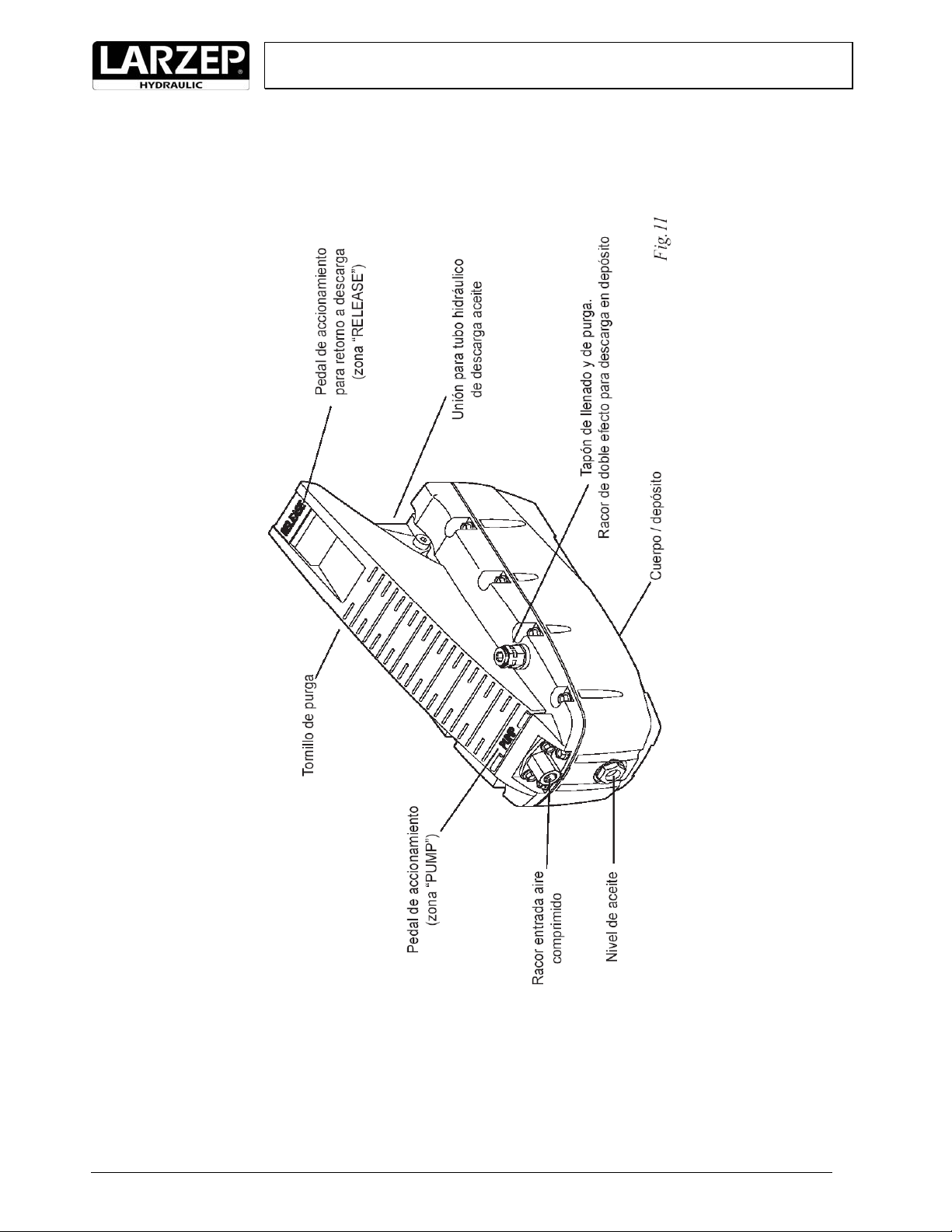
5. MAINTENANCE
The hydraulic circuit of the press is closed, so in normal conditions no oil leakage should be coming up.
In case of oil leakage, after the proper repairing work, you should fill up the tank with hydraulic oil by LARZEP (Ref: AZ8902). The electric pump is equipped
with an oil level indicator to control the need quantity of oil.
As far as a non-continuous use of the press is concerned (1 hour per day), oil replacement should be done once a year. To empty the tank, you should remove the
cover and take the oil out to another container. Please, bear in mind the existing rules for waste processing when handling the used oil.
Keep greasy and lubricated the pin bearings, the piston and in general all the parts that might be in friction.
IMPORTANT: In case of working with pressures superior to 400kg/cm², substitute the given gauge by one suitable for the
required pressure.

5
INSTRUCTIONMANUAL
ColumnPresswithHydropneumaticPump"EZ03015"
SYMPTONS POSIBLE CAUSE SOLUTIONS
1 Piston does not extend 1.1 Prime less
p
ump 1.1 Maintain the pump started for some minutes in "C" position.
1.2 Filter is dirty. 1.2 Remove and clean it properly.
1.3 Not enou
g
h oil in the tan
k
1.3 Check the oil level.
1.4 Pressure retainer dama
g
ed. 1.4 Replace the retainer.
1.5 Cylinder body damaged. 1.4 Repair the cylinder body.
1.6 Distribution valve dama
g
ed. 1.5 Repair the valve.
1.7 Pneumatic problem 1.7 Check the installation
2 Cylinder does not reach pressure. 2.1 Internal valve unrated 2.1 Rate again the valve.
2.2 Pressure retainer dama
g
ed. 2.2 Replace the retainer.
2.3 C
y
linder bod
y
dama
g
ed. 2.3 Repair the cylinder body.
3 Cylinder does not hold pressure. 3.1 Pressure retainer damaged. 3.1 Replace the retainer.
3.2 Distribution valve dama
g
ed 3.2 Repair the valve.
4 Cylinder does not retract. 4.1 Pressure retainer damaged. 4.1 Cambiar el retén.
4.2 Distribution valve dama
g
ed. 4.2 Repair the valve.
Solutions written in bold face should be done by specially trained staff.
In the attached documents, the components of the Spare Kits are marked with (*), in order to effect the a.m. repair jobs. Use always original LARZEP repair kits.
6.WARRANTY
LARZEP, S.A. guarantees its products against all design and manufacturing defects for the durations of two years from the date of purchase. This guarantee does
not include the ordinary wear of both metal and non-metal parts, abuse, using the equipment beyond its rated capacity and any wear or damage incurred as a result
of using a hydraulic fluid which is not recommended by LARZEP, S.A.
Please note that if the equipment is disassembled or serviced by anyone other than an authorized service dealer or by LARZEP, S.A., this guarantee is rendered
null and void.
In the event of a warranty claim, return the equipment, to LARZEP, S.A. or the authorized dealer which sold you the hydraulic equipment, LARZEP, S.A. will
repair or replace the faulty equipment, whichever is deemed most appropriate. LARZEP, S.A. shall not be held liable for any consequential damages or losses,
which may occur as a result of faulty equipment.

6
INSTRUCTIONMANUAL
ColumnPresswithHydropneumaticPump"EZ03015"
7. DECLARACIÓN DE CONFORMIDAD

7
INSTRUCTIONMANUAL
ColumnPresswithHydropneumaticPump"EZ03015"
DRAWINGS & COMPONENTS

8
INSTRUCTIONMANUAL
ColumnPresswithHydropneumaticPump"EZ03015"
CYLINDER SM03015

9
INSTRUCTIONMANUAL
ColumnPresswithHydropneumaticPump"EZ03015"
HYDROPNEUMATIC PUMP Z12107
Table of contents
Other Larzep Power Tools manuals

Larzep
Larzep CA1014 User manual

Larzep
Larzep EE06018 User manual

Larzep
Larzep ECE02013 User manual

Larzep
Larzep ECE02015-CE User manual

Larzep
Larzep ECE01113-CE User manual

Larzep
Larzep ECE02013-CE User manual

Larzep
Larzep EM06018 User manual

Larzep
Larzep EE03116-CE User manual

Larzep
Larzep ECE01113 User manual

Larzep
Larzep EE25030-CE User manual

Larzep
Larzep EM03012 User manual

Larzep
Larzep ECM01113 User manual

Larzep
Larzep ECZ01113 User manual

Larzep
Larzep EE12018 User manual

Larzep
Larzep EE03116 User manual

Larzep
Larzep EE25030-CE/L User manual

Larzep
Larzep EE06018-CE User manual

Larzep
Larzep ECE01115 User manual

Larzep
Larzep EE12018-CE User manual