manuals.online logo
Brands
  1. Home
  2. •
  3. Brands
  4. •
  5. Laserworld
  6. •
  7. Lighting Equipment
  8. •
  9. Laserworld LW-50k User manual

Laserworld LW-50k User manual

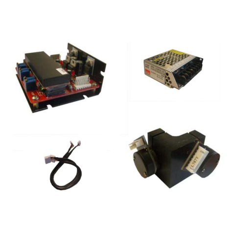
Scanner Set LW-50k
Manual
Please read carefully before use
Bedienungsanleitung
Bitte lesen Sie diese Bedienungsanleitung, bevor Sie das Gerät in Betrieb neh en!
Bedienungsanleitung: Laserworld Scanner Set CT-6210
Date: Dec-10
Seite
2
von
5
The LW-50k is a fast scanning syste , perfect for
bea shows, but also for graphics projection.
Checking Parts
Please ake sure the following parts
are included:
2 x Galvos
2 x ounted irrors
1 x X/Y-Galvo- ount
2 x driver
2 x galvo cables
1 x power supply
1 x User anual
Technical data
- scanspeed: ax. 50Kpps at 4°
- optical scan angle: ax. 60°
- power supply: +/-24V 1A
- dielectric irrors
- optical feedback syste for high
accuracy
- scan angle individually adjustable per axis
- overcurrent protection
-Scanner te perature 50°C ax
Sy etrical signal input
+/- 5V DC (ILDA co patible)
Connectors
Das Laserworld LW-50k Scanner Set ist ein sehr schnelles
Scannsyste , für Bea -, aber auch Grafikshows.
Lieferumfang
Bitte prüfen Sie, ob Sie wirklich alle Teile erhalten haben
und ob diese von der Lieferung unbeschädigt sind. Zu
Lieferu fang gehören:
2 x Galvos
2 x ontierte Spiegel
1 x X/Y-Galvo-Halter
2 x Treiber
2 x Galvokabel
1 x Stro versorgung
1 x Bedienungsanleitung
Technische Daten:
- Scangeschwindigkeit: 50Kpps bei 4°
- optischer blenkwinkel: ax. 60°
- Stromversorgung: +/- 24V 1A
- dielektrische Spiegel
- Zweikanaltreiber
- optisches Feedbacksyste für perfekte Genauigkeit
- Scanwinkel pro Achse individuell einstellbar
- Überstro sicherung
- Maxi al 50°C Scannerte peratur
Sy etrischer +/-5V Eingang (ILDA ko patibel)
nschlüsse:
+24V (PSU)
Ground (PSU)
-24V (PSU)
Ground (PSU)
Feedback
Ground (ILDA)
Input- (ILDA)
Input + (ILDA)
to galvo
Angle / Winkel ~30° ~15° ~5°
Speed 17-19,000 pps 25-27,000 pps 37-50,000 pps
Bedienungsanleitung: Laserworld Scanner Set CT-6210
Date: Dec-10
Seite
3
von
5
Installation
The driver/scanner pairs
are adjusted at the
factory and arked X and
Y respectively, do not
exchange.
The picture to the right
shows a basic setup
(laser bea entering
fro the left)
Driver:
The feedback signal is for
safety boards. If not used, do not connect.
Connect the signals arked with (PSU) to the
corresponding signals on the power supply (see
below).
Connecting to ILDA output: connect the signals
arked (ILDA) to the following pins of a 25 pin
ale Sub D connector:
Input+ of X driver to pin 1, Y driver to pin 2
Input- of X driver to pin 14, Y driver to pin 15
Ground (both drivers) to pin
Power supply:
Connect the
outputs to the
corresponding
signals on both
driver boards.
Connect L, N
and protective
ground to
ains.
Mounting the galvos
the picture to the right shows
how the galvos are ounted
into the galvo ount.
(Laserbea entering fro
botto of the picture, X galvo
ounted fro the right, Y
galvo fro top). Tighten the
screws in the galvo ount, so
the galvos can not ove.
Installation
Das Scannerpaar wird in der Fabrik
eingestellt, Treiber und Scanner sind
it X und Y arkiert, bitte nicht
vertauschen.
Das linke Bild zeigt eine
Standardinstallation (Laserstrahl von
links)
Treiber:
Das Feedback Signal ist für eine
optionale Strahlüberwachung. Falls
Sie keine solche verwenden, das
Signal nicht anschliessen.
Schließen Sie die Signale, die it (PSU) arkiert sind, an
die entsprechenden Anschlüsse auf der
Spannungsversorgung an (Siehe unten).
Verbindungen zu ILDA Ausgang: Schließen Sie die
arkierten Signale (ILDA) an die folgenden Pins eines 25
Pin Sub D Stecker an:
Input+ des x-Treibers zu Pin1, Y Treiber zu Pin2
Input+ des x-Treibers zu Pin14, Y Treiber zu Pin15
Ground/Masse (beide Treiber) zu Pin 25
Stromversorgung:
Schließen Sie die
Ausgänge an die
entsprechenden
Signale auf beiden
Treiberplatten an.
Schließen Sie L, N und
Schutzerde an Ihre
Stro versorgung an.
Montage der Galvos
Die linke Abbildung zeigt, wie die
Galvos in der Halterung angebracht
werden.
Der Laserstrahl ko t von der
Unterseite der Abbildung herein, der X
Galvo wird von rechts angebracht, der Y
Galvo von der Oberseite). Ziehen Sie
die Schrauben in der Galvoeinfassung
fest, so dass Sich die Galvos nicht
bewegen können.
Bedienungsanleitung: Laserworld Scanner Set CT-6210
Date: Dec-10
Seite
4
von
5
djustments Einstellungen
Scanners are adjusted
at the factory, don’t
exchange X and Y
Adjust ent using the
ILDA test pattern:
Display the ILDA test
pattern at the
scanspeed and i age
size for which you
want to adjust your
scanning syste .
Adjust da ping: At the
corners of the inner square
you can have an
overshoot or undershoot of
the laserbea (see i ages
above). Adjust HFD and LFD
to ini ize this effect. (See
above for position of potis.)
Adjust servo gain: As long as
the top and botto of the
circle lie within the square
(regardless of the for , it ay be ore of an ellipse) you
can increase gain. The top/botto will then ove outwards.
Increase until the circle/ellipse touches the square.
Repeat these two steps until you get a good result.
Do the sa e for X, until the circle touches the square at all
4 sides.
You ay have to repeatedly adjust both X and Y until the
circle is perfectly round.
Scanspeed and i age size:
If the circle is bigger than the square you can increase
scanspeed, or picture size. Your syste is faster than
necessary for that size.
If the circle is inside the square you should decrease
scanspeed or i age size. Your syste is not fast enough for
that size.
If you have to adjust fro scratch (e.g. because you replace
a single, not preset galvo) first turn gain/LFD/HFD to zero
(counter clock wise), then start increasing gain carefully
until the galvos start oving, proceed as above.
Das Scannerpaar wird in der
Fabrik eingestellt, bitte X und Y
nicht vertauschen.
Einstellung it de ILDA
Testbild
Projizieren Sie das ILDA Testbild
bei der von Ihnen gewünschten
Auslenkung und
Scangeschwindigkeit.
Beachten Sie nun die Ecken des
inneren Quadrats.
Justieren Sie die Dä pfung: An den
Ecken des inneren Quadrats kann ein
Über- oder Unterschiessen auftreten
(entsprechend Bilder links) Justieren
Sie HFD und LFD, u diesen Effekt
herabzusetzen. (Lage der Regler
siehe oben.)
Erhöhen Sie Gain: Solange die
Oberseite und die Unterseite des
Kreises innerhalb des Quadrats liegen
(unabhängig von der For - kann
zunächst auch eine Ellipse sein),
können Sie Gain erhöhen. Die
Oberseite/die Unterseite bewegen
sich dann nach aussen. Erhöhen Sie
solange, bis der Kreis/die Ellipse das
Quadrat berührt.
Wiederholen Sie diese beiden
Schritte, bis Sie ein gutes Ergebnis
haben.
Wiederholen Sie dies für X, bis der
Kreis das Quadrat an allen 4 Seiten
berührt.
Sie üssen X und Y eventuell
wiederholt justieren, bis der Kreis
rund ist.
Scanspeed und Bildgröße: Solange der Kreis größer
als das Quadrat ist, können Sie die
Scanngeschwindigkeit oder die Bildgröße erhöhen.
Ihr Syste ist schneller als für diese Größe
notwendig.
Wenn der Kreis kleiner als das Quadrat ist, üssen
Sie die Scanngeschwindigkeit oder die Bildgröße
verringern. Ihr Syste ist langsa er als für diese
Größe notwendig.
Falls Sie die Einstellungen ko plett neu
vorneh en üssen, weil Sie z.B. nur ein einzelnes
nicht abgeglichenes Galvo austauschen drehen Sie
zunächst alle Regler auf Null (gegen den
Uhrzeigersinn). Dann drehen Sie Gain auf, bis die
Galvos anfangen sich zu bewegen. Fahren Sie wie
oben fort.
Bedienungsanleitung: Laserworld Scanner Set CT-6210
Date: Dec-10
Seite
5
von
5
Laserworld (Switzerland) G
Kreuzlingerstrasse 5
8574 Lengwil-Oberhofen
SWITZERLAND
Authorized person:
Supervisory board Mr Martin Werner
place of business: 8574 Lengwil-Oberhofen / SWITZERLAND
co pany nu ber: CH-440.3.020.548-6
Co ercial Registry Kanton Thurgau
www.laserworld.co
info@laserworld.co
representative according to EMVG:
Cleantech Europe G bH
Managing Director: Tho as Schulze
Fürkhofstr. 5
81927 München / DE

Other Laserworld Lighting Equipment manuals

Laserworld Garden Star Series User manual

Laserworld

Laserworld Garden Star Series User manual

Laserworld Club Series User manual

Laserworld

Laserworld Club Series User manual

Laserworld BeamBar 10R-638 User manual

Laserworld

Laserworld BeamBar 10R-638 User manual

Laserworld RTI-Piko Series User manual

Laserworld

Laserworld RTI-Piko Series User manual

Laserworld PL-3000RGBNL User manual

Laserworld

Laserworld PL-3000RGBNL User manual

Laserworld EL-150B User manual

Laserworld

Laserworld EL-150B User manual

Laserworld Ecoline EL-D100G User manual

Laserworld

Laserworld Ecoline EL-D100G User manual

Laserworld BLUE-1300-445 User manual

Laserworld

Laserworld BLUE-1300-445 User manual

Laserworld GREEN-75E User manual

Laserworld

Laserworld GREEN-75E User manual

Laserworld CS-200RGY User manual

Laserworld

Laserworld CS-200RGY User manual

Laserworld Ecoline Series User manual

Laserworld

Laserworld Ecoline Series User manual

Laserworld Evolution ES-600B User manual

Laserworld

Laserworld Evolution ES-600B User manual

Laserworld Evolution ES-800RGB User manual

Laserworld

Laserworld Evolution ES-800RGB User manual

Laserworld LED-54 User manual

Laserworld

Laserworld LED-54 User manual

Laserworld CS-100G User manual

Laserworld

Laserworld CS-100G User manual

Laserworld GREEN-300 User manual

Laserworld

Laserworld GREEN-300 User manual

Laserworld CS-8000RGB FX MK2 User manual

Laserworld

Laserworld CS-8000RGB FX MK2 User manual

Laserworld SwissLas Purelight PL-8000G compact User manual

Laserworld

Laserworld SwissLas Purelight PL-8000G compact User manual

Laserworld BLUE-400-445 User manual

Laserworld

Laserworld BLUE-400-445 User manual

Laserworld RB-1.5 User manual

Laserworld

Laserworld RB-1.5 User manual

Laserworld GREEN-5000C User manual

Laserworld

Laserworld GREEN-5000C User manual

Laserworld GREEN-400 User manual

Laserworld

Laserworld GREEN-400 User manual

Laserworld Evolution Series ES-800S RGB 3D Assembly instructions

Laserworld

Laserworld Evolution Series ES-800S RGB 3D Assembly instructions

Laserworld V PRO-OEM User manual

Laserworld

Laserworld V PRO-OEM User manual

Popular Lighting Equipment manuals by other brands

LUG LUGCLASSIC SLIM LB LED Installation instruction

LUG

LUG LUGCLASSIC SLIM LB LED Installation instruction

Generac Power Systems CTF 10m owner's manual

Generac Power Systems

Generac Power Systems CTF 10m owner's manual

Equinox Systems EQLED203 user manual

Equinox Systems

Equinox Systems EQLED203 user manual

GENI COLOR BLASTER CB-250 COLOR BLASTER CB-250B instruction manual

GENI

GENI COLOR BLASTER CB-250 COLOR BLASTER CB-250B instruction manual

Light Emotion FLAT1012 User instruction manual

Light Emotion

Light Emotion FLAT1012 User instruction manual

Venture Lighting EMG016 Instruction

Venture Lighting

Venture Lighting EMG016 Instruction

LIGMAN LIGHTALK 7 installation manual

LIGMAN

LIGMAN LIGHTALK 7 installation manual

Pentair Pool Products Rainbow Lifeguard 300 installation instructions

Pentair Pool Products

Pentair Pool Products Rainbow Lifeguard 300 installation instructions

Osram Clay Paky ALPHA SPOT 300 instruction manual

Osram

Osram Clay Paky ALPHA SPOT 300 instruction manual

Seiwa LCTD110181-N instruction manual

Seiwa

Seiwa LCTD110181-N instruction manual

lumen8 Kudos 150 user manual

lumen8

lumen8 Kudos 150 user manual

Anslut 002-474 operating instructions

Anslut

Anslut 002-474 operating instructions

Kaiser Fototechnik studiolight E70 Kit operating instructions

Kaiser Fototechnik

Kaiser Fototechnik studiolight E70 Kit operating instructions

Saxby Lighting Hero CCT instruction manual

Saxby Lighting

Saxby Lighting Hero CCT instruction manual

MELINERA HG02037A Operation and safety notes

MELINERA

MELINERA HG02037A Operation and safety notes

Chauvet DJ Bank user manual

Chauvet

Chauvet DJ Bank user manual

Osram 660 user manual

Osram

Osram 660 user manual

Chroma Color Block 2 Plus Nano user manual

Chroma

Chroma Color Block 2 Plus Nano user manual

manuals.online logo
manuals.online logoBrands
  • About & Mission
  • Contact us
  • Privacy Policy
  • Terms and Conditions

Copyright 2025 Manuals.Online. All Rights Reserved.