Lauda Puridest PD 2 D User manual

Operating Instructions
Puridest BiDistillationApparatus
PD 2 D, PD4 D, PD8 D

2 / 32 Puridest Bi Distillation Apparatus 09/2020

0
9
/2020
Puridest Bi
Distillation Apparatus
3
/
32
LAUDA Puridest Bi Distillation Apparatus models PD 2 D,PD 4 D, PD 8D produce ultra-pure, bacteria and pyrogen-free
distillate with a very low conductivity (approx 1.6 µS/cm at 25°C).The distillate is in conformity with DAB regulations and
the regulations of international pharmacopoeia.
I II III IV V VI
I Main switch
II Pilot lamp "Operation Mono stage"
III Pilot lamp "Low water Mono stage"
IV Pilot lamp "Clean“
V Pilot lamp "Operation Bistage"
VI Pilot lamp "Low water Bi stage"
Before installation, please check whether contents of package are in good order and complete.
Should younote any damages or have any reasons for complaint, please contact your supplier or directly.
LAUDA-GFL Gesellschaft für Labortechnik mbH
Schulze-Delitzsch-Str. 4+5
30938 Burgwedel - Deutschland
Telefon: +49(0)5139 9958 0
Fax: +49 (0)5139 995821
E-Mail: info@lauda-gfl.de
Internet: www.gfl.de

4 / 32 Puridest Bi Distillation Apparatus 09/2020

0
9
/2020
Puridest Bi
Distillation Apparatus
5
/
32
Content
Operating Instructions...................................................................................................................................................................1
1 Usingof the Bi Distillation Apparatus...................................................................................................................................7
Intended Use...................................................................................................................................................................................7
1.1
Improper Use..................................................................................................................................................................................7
1.2
2 Warranty................................................................................................................................................................................8
3 Before Initiation.....................................................................................................................................................................8
4 Transport,Set-up and Location of the Distillation Apparatus..............................................................................................8
5 Removing the Transport Protection of the Glass Condenser...............................................................................................9
6 Operating Voltage.................................................................................................................................................................9
7 Water Connections.............................................................................................................................................................10
Tap water inlet①.........................................................................................................................................................................10
7.1
Inlet separate water supply ❷...................................................................................................................................................10
7.2
Outlet separate water supply ❹...............................................................................................................................................10
7.3
Cooling water outlet ⑥...............................................................................................................................................................11
7.4
Drain Bi-stage boiler⑦...............................................................................................................................................................11
7.5
Drain Mono stage boiler ⑧........................................................................................................................................................11
7.6
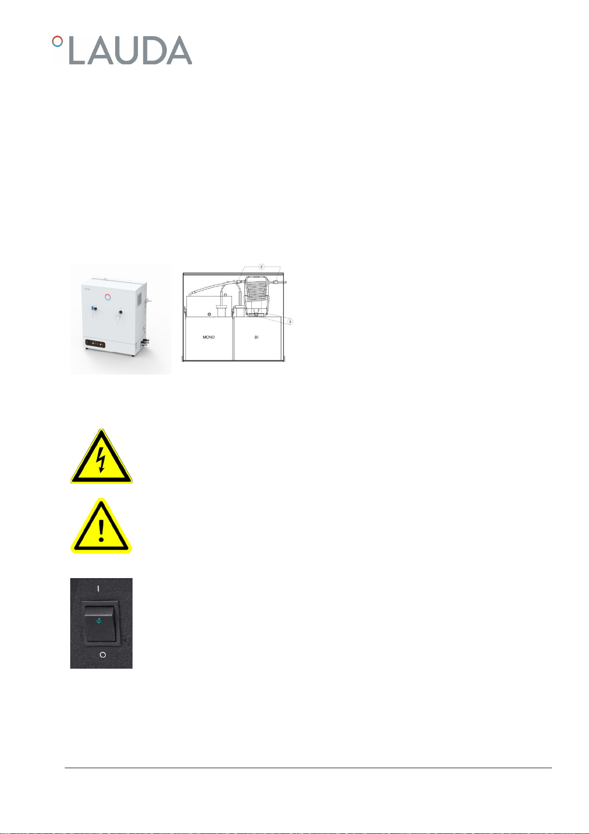
8 Initiation..............................................................................................................................................................................11
9 FunctionalDescription.......................................................................................................................................................12
Distillation Apparatus for double distillation............................................................................................................................12
9.1
Bi Distillation Apparatus withseparate water supply.............................................................................................................12
9.2
Degassing.......................................................................................................................................................................................12
9.3
10 Maintenance,Service andTrouble Shooting......................................................................................................................13
Descaling........................................................................................................................................................................................13
10.1
Sterilising........................................................................................................................................................................................13
10.2
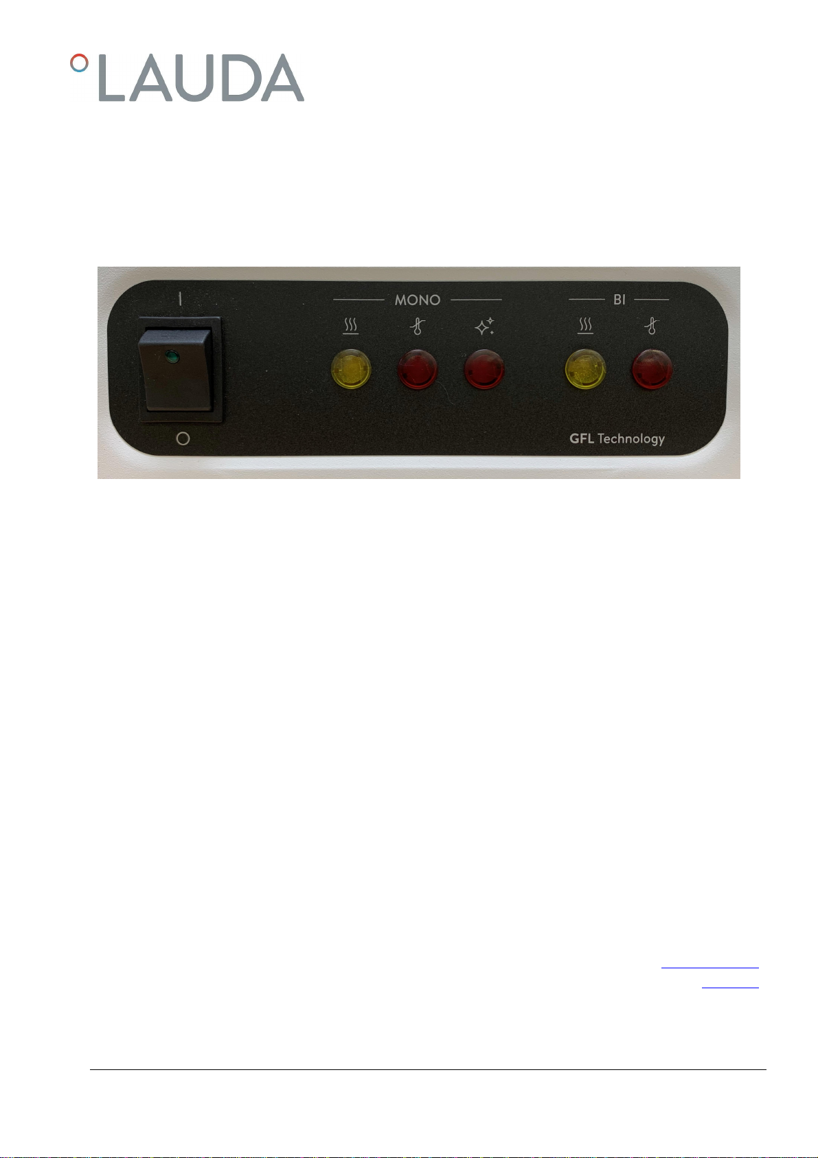
Water shortage in mono or bi stage..........................................................................................................................................14
10.3
Pilot lamp "Clean".........................................................................................................................................................................14
10.4
11 Disposal of Old Units..........................................................................................................................................................15
12 TechnicalData....................................................................................................................................................................16
Puridest Bi Distillation Apparatus models PD 2 D, PD 4D................................................................................................16
12.1
Puridest Bi Distillation Apparatus model PD 8 D..................................................................................................................17
12.2
13 Circuit diagram...................................................................................................................................................................18
PD 2 D...........................................................................................................................................................................................18
13.1

6 / 32 Puridest Bi Distillation Apparatus 09/2020
PD 4 D - version 220 V / 3 ~..................................................................................................................................................19
13.2
PD 4 D - version 400 V / 3 ~..................................................................................................................................................19
13.3
PD 8 D - version 220 V / 3 ~..................................................................................................................................................20
13.4
PD 8 D - version 400 V / 3 ~..................................................................................................................................................20
13.5
14 Connectionto the mains supply.........................................................................................................................................21
Connection to the mains supply (examples)..........................................................................................................................22
14.1
14.1.1 PD 2 D for 230V............................................................................................................................................................. 22
14.1.2 PD 4 D and PD 8D for 220 V / 3 ~at Mains supply 230V / 3 ~ / PE 50 / 60 Hz.......................................23
14.1.3 PD 4 D and PD 8D for 220 V / 3 ~at Mains supply 230V / 3 ~ / PE 50 / 60 Hz.......................................23
14.1.4 PD 4 D and PD 8D for 400 V / 3 ~at Mains supply 400V / 3 ~ / N/ PE 50 / 60Hz.................................24
14.1.5 PD 4 D and PD 8D for 400 V / 3 ~at Mains supply 400V / 3 ~ / N/ PE 50 / 60Hz.................................24
15 List of spare parts................................................................................................................................................................25
16 Accessories andOptions.....................................................................................................................................................27

0
9
/2020
Puridest Bi
Distillation Apparatus
7
/
32
1 Using of the Bi Distillation Apparatus
Intended Use
1.1
In LAUDA Puridest Bi Distillation Apparatus models PD 2 D,PD 4 D and PD 8D, electric heating elementsserve to boil
water in the mono stage boiler (left-hand side)and evaporate it. The steam is led to the steel condenser of the mono stage
where it condenses on a water-cooled cooling coil. The produced distillate drips into the boiler of the bi stage (right-hand
side), or can be withdrawn through a stop cock made of borosilicate glass. The electric heating elements inthe bi stage
bring the water in the right-handside alembic to the boil. The steam is led into the condenser of thesecond distillation
stage and condenses as bi distillate on a water-cooled cooling coil.The condenser of the bistage, including the splash
protection and cooling coil as well as the complete bi distillate outlet with dust cover are made of Duran® / borosilicate
glass 3.3.
The filling level of both boilers is monitored by two floatswitches, the heating elements of both stagesare additionally
controlled by thermostatic lowwater cut-offs. After switchingthe Double Distiller on, it is automatically operated.
Dependingon the model, theDouble Distiller produces approx. 2 litres (PD 2D), 4 litres (PD 4 D) or 8 litres (PD 8 D)
bidistillate perhour.
Mono- and Bi-distillate is withdrawn through the two glass fittings at the front of the unit. Attention, the distilled water
leaves the Distillation Apparatus with more than 90 °C!Danger of scaldings! Depending on thetap water quality, the
produced mono distillate has a conductivity of approx. 2.2 µS/cm at 25°C. The produced bi distillate is dependent on
the qualityof the evaporated mono distillate and has a conductivity of approx. 1.6 µS/cm at 25°C. To feed the Distillation
Apparatus, preferably use tap water of drinking quality. Pleasealso observe the information in chapters 17.2 to 17.4of
these instructions on the possible use of filters andcartridges to pretreat the tap water .
The Bi Distillation Apparatus must be operated within the user's field of vision.
The information contained in these operating instructions must by all means beread and observed. Only
then a perfectoperationof the Bi Distillation Apparatus can beguaranteed. The units may only be installed
and operated by persons who have made themselves familiar with these operating instructions.
Caution:
The accessible inner parts of the housing that can be reached after removingthe outer white cover get
strongly heated up during operation. These parts may only betouched after they have cooled down, or
when wearingsuitable safety gloves.
Improper Use
1.2
LAUDA Puridest Bi Distillation Apparatus, operated in a laboratory, are no Medical Devices. They fall neither under na-
tional nor international MedicalDevice Directives and have to be used and applied accordingly. The Distillation Apparatus
must not be used in potentially explosive surroundings. The Distillation Apparatus mustneither beset up nor operated in
laboratory areas with aggressive or corrosive ambient conditions.

8 / 32 Puridest Bi Distillation Apparatus 09/2020
2 Warranty
For all laboratory apparatus and their accessories from LAUDA-GFL Gesellschaft für Labortechnik mbH, there is a war-
ranty claim, as well for spare parts, repairs and modifications, carriedout by LAUDA-GFL. In order to identify defective
units, we require both model and serial number on the nameplate, left-handside of the Distillation Apparatus and, if appli-
cable, a copyof the invoice.
3 Before Initiation
Important information are marked in boldletters in these instructions, safety indications are additionally markedby the fol-
lowing warning symbols and mandatory signs.
Read and observe the
operating instructions
Warning of hot liquids
and vapour Warning of hot surfaces
Warning of dangerous
electrical voltage General warning Before maintenance and repair
disconnect the unit all-pole from
the electrical mains (pull the plug
from the socket).
4 Transport, Set-up and Location of the Distillation Apparatus
Protect yourself and the Distillation Apparatus during transport and setupby working carefully and
avoid dangerof e. g. shifting or tilting the unit as well asrisk of injury by liftingheavy loads. Caution,
Distillation Apparatus PD 2 D(net weight 20.4 kg), PD 4D (net weight 27.5 kg)and PD 8 D (net
weight 43,0kg) must be lifted, carried and transported to the location by at least two persons.
The Distillation Apparatus can be held between the fourstands of the unit and lifted forsetup.
The unit is suitable for both bench and wall mounting. It is only suitable for indoor use. Table-top setting-up on solid, even
and levelsurfaces only. Make sure to placethe unit only on a watertight,temperature-resistant,non-flammablesurface.
The locationmust provide sufficient space as well as the necessary carrying capacity for the total weight ofthe Distillation
Apparatus (unit weight as per Technical Data of this manual, plus weight of the filling).
For setting-upon the wall check the carrying capacity ofthe wall in connection with the total weight of the unit (appliance
plus water filling, see Technical Data). Makesure to check the on-site fixing elements in order to guarantee safe holdof
the Distillation Apparatus. The fixing material must be suitable for the substrate. Use only tested and proven fixing materi-
al.
There are two keyholes for wall mounting at the back ofthe Distillation Apparatus. Place two fixing screws (not included in
the scopeof supply) in the wall, 40 cm apart, and nest thestill on the keyholes. The Distillation Apparatus is delivered
without fixing material.

0
9
/2020
Puridest Bi
Distillation Apparatus
9
/
32
5 Removing the Transport Protection of the Glass Condenser
When installing the glass condenser and the glass fittings, pay special attention due to danger of glass breakage.
The glass condenser and the glass fittings are placed beneath the hood of the Distiller. In order to be able to remove the
hood, two each quick-release catches on each side of the unitas well as two hidden screws (see photo below) between the
hood and the basic housing need to be loosened.
Before initiation, remove the transport protection (bubble wrap and rigid foam parts) around the glass condenser, clear all
connection openings that are covered by adhesive tape or plastic film and carefully empty the sand from the condenser.
Rinse the condenser with clear water and re-assemble as shown below. Place the cone of the glass condenser into the
plastic ring on the right-hand side boiler. The bi-distillate outlet must point to the front. Place the round felt washer on top
of the glass condenser; it will prevent dislodging of the holding clamp which is connected with the unit through the four
holdingarms ③. Fit together those hose couplings ②having thesame colour.
Place the hood back onto the unit and secure with the two
screws and four quick-release catches. Then install the glass
fittings. Screw together the glass valve with the mono-
distillate outlet (left-hand front of the unit), and the outlet
tube with the bi-distillate outlet.
6 Operating Voltage
The Distillation Apparatus must be connected tothe mains supply through a correctly installed, on-site
main switch, or, permanently connected,through a CEE plug in conformity with IECstandard 60309-
2. The unit isa protection class I electrical appliance, a connection to the protective earth is to be en-
sured. For information on the value of therequired mains fuse see Technical Data, chapter 12,of these
instructions.
The electrical connection must ensure an all-pole separation from the mains at any time. Shock-proof
sockets ormain switches to separate the Distillation Apparatusfrom the mainsmust be installedinsuch
a way as toensure clear identifiability and easy accessibility at any time.
The mains connection cable must not touch any hot surfaces of the unit. It may not lead underneath
the unit. The main switch of the Distillation Apparatus must be off (position O). The voltage on the
nameplate (at the left-handside of the unit) must be identical to the mains voltage. If they are identical,
connect the unit to the mains.
Please also refer to chapter 15 of these operating instructions "Connection to theMains"..

10 / 32 Puridest Bi Distillation Apparatus 09/2020
7 Water Connections
All water connections of the Distillation Apparatus, exceptthe distillate withdrawals, are situated on the right-hand side of
the unit. Hoses for water inlet and outlet arenot included in thestandard scope ofsupply.
Tap water inlet ①
7.1
The tap water inlet provides the Distillation Apparatus with water through a solenoid valve. The hose connection must be
connected to the water mains supply with a ½" (inch,Æinside12.7mm) pressure hose and a lockable water connection (
③, cut-off valve). Both hose connections must by all means be secured with hose clips!
Inlet separate water supply❷
7.2
Part of an accessory. Only fitted if a separate water supply was ordered.
The water inlet for theseparate water supply ❷feeds pretreated water to the boiler of the Distillation Appa-
ratus through a solenoid valve with built-in quantity regulator (0.5 l/ min). The hose connection must be connected to the
domestic water connection for pretreated water with a ½" pressure hose and a lockable water connection (❺, cut-off
valve). Both hose connections must by all means be securedwith hose clips!
Outlet separate water supply ❹
7.3
Part of an accessory. Only fitted if a separate water supply was ordered.
Connect a ½" hose to the out connectionof the separate watersupply ❹and lead it into a drain, imperatively on
a lower level. It must not be longer than approx. 1.5m. The hose musthave a slope on the complete length, it must be
ensured thatthe water flows off without causing backwater.

0
9
/2020
Puridest Bi
Distillation Apparatus
11
/
32
Cooling water outlet ⑥
7.4
Connect a¾" temperature-resistant hose to the cooling water outlet. It must not be longer than approx. 1.5m. The hose
must be led into a drain on a lower level and must have aslope on its complete length. It must be ensured that the cooling
water flows off without causing backwater.
Caution:
The cooling water leaves the Distillation Apparatus with temperatures of up to 70°C.
Danger ofscaldings!
Drain Bi-stage boiler⑦
7.5
A ½" hoseto drain the boiler for cleaning or maintenance can be connected.
Caution:
The water leaves the boiler of the Distillation Apparatus withtemperatures of upto 100 °C.
Danger ofscaldings!
Drain Mono stage boiler ⑧
7.6
A ½" hoseto drain the boiler for cleaning or maintenance can be connected.
Caution:
The water leaves the boiler of the Distillation Apparatus withtemperatures of upto 100 °C.
Danger ofscaldings!
Water connections pos. ❷and❹are parts of an accessory. They are only fitted if aseparate water
supply was specifically ordered with the unit.The depictedsupply valve pos. ❺is only required if the
unit is equipped with a separate water supply.
8 Initiation
After assemblyof all power and water connections, and to initiate the Distillation Apparatus, the stop valves ofthe water
supply (③and ❺) must be opened and the main switch (I) must be switchedon. The first litres of produced distillate
(mono and bi distillate) should not be used. Between switchingthe Distillation Apparatus off and then onagain, always wait
for approx. 10seconds as the unit will otherwise be switched into "Clean" mode.
During down-times of the Distillation Apparatus, all cut-off valves of the water supplyshould always be closed.

12 / 32 Puridest Bi Distillation Apparatus 09/2020
9 Functional Description
Distillation Apparatus for double distillation
9.1
LAUDA Puridest Bi Distillation Apparatus models PD 2 D, PD 4 D und PD 8 D work fully automatically. After switching
on the main switch oft he Distillation Apparatus, the green pilotlamp in the main switch (I) will light up.
The built-in solenoid valve will open. Water flows through the cooling coil of the glass condenser in the bi stage as well as
the cooling coil of the condenser in the mono stage, and fills
the mono stage boiler with tap water, regulated by a mechan-
ical water level regulator. The water level regulator deter-
mines the water level in the boiler. Water that is not used for
evaporation will flow off through the cooling water outlet
I II V
The water levels in the boilers are monitored by float switches (S2/S3), which switch on the heatingelement and protect
them from running dry. Additionally, the heating elements of both distillation stages are controlled by thermostatic low
water cut-offs (F1/F2), that protect the Distillation Apparatus from over-heating. Once the heating elements in the
mono boiler are beneath water level, they are switched on andbring the water to the boil.The produced steam rises upand
condenses on the cooling coil of the mono stage steel condenser. Mono distillate can be withdrawn through the borosili-
cate glass stop valve on the front of the unit. If the glass valve for withdrawal of mono distillate is closed, the mono-distilled
water is led into the boiler of the bi stage. Once the heating elements in the bi stage are below water level, the heating
elements areswitched on. The mono distillate in the bi stage boiler is brought to the boil. The produced steam condenses in
the glass condenser of the bi stage and flows off as bi distillate through the outlet tube with dust cover that is screwed to
the condenser.The maximum water level in the bi stage boiler is limited by an overflow to the cooling water outlet. Opera-
tion mode of the heating elements in both stages is indicated by yellow pilot lamps (II and V). When the Bi Distillation
Apparatus isoperated for the first time, the procedure until production of bi-distillate will take approx. 2 hours.
Bi Distillation Apparatus with separate water supply
9.2
Only factory installation into models PD 2 Dto PD 8 Dis possible.
The separate water supply serves to feed the monostage boiler with pretreated water and the cooling coils with phospha-
tized or normal tap water. Tap water is fed to the boiler through a solenoid valve (Y2) with approx. 0.5 litres per minute.
Water that is not required flows off through the "outlet separate water supply". The condensers are fed with cooling water
through a secondsolenoid valve (Y1).The cooling water flows off throughthe cooling water outlet.
Owing to the separation of cooling and tap water, the water fed to the boiler is not pre-heated, the efficiency of the still is
therefore reduced by approx. 10-15%.
Degassing
9.3
Carbon dioxide is released throughthe twoexhaust tubeson the top ofthe unit.

0
9
/2020
Puridest Bi
Distillation Apparatus
13
/
32
10 Maintenance, Service and Trouble Shooting
Caution:
Before service and maintenance always let the Double Distillercool down!
Danger ofscaldings!
Caution:
Before opening the Distillation Apparatus and before cleaning always cut off power (pull
the plug or switch the main switch off).
Danger of electrical shocks!
Descaling
10.1
Dependingon the degree of hardness ofthe tap water,the Distillation Apparatusmust be descaled in regular intervals. To
do so, remove the glass fittings, the outer hood, the steel condenser ofthe mono stage and the deflector plate beneath
the condenser (observe exact position for re-assembly).
A suitable descaling agent would be a mixture of 10 % formic acid, 10% acetic acid and80 % distilled water. Fill this solu-
tion into the boiler up to the top rim of the lime deposits and heat to maximum 70 °C. Make absolutely sure not to bring
the solution to aboil. For this, close valves (③+⑤) andswitchon the distiller until the temperature is reached. After ap-
prox. 30 minutes, drain the descaling agent/scale mixture through the drain cock "drain mono stage boiler" ⑧andrinse
the boiler with clear waterseveral times.
Commercial descaling agents, suitable for use with stainless steel, can also be used according to the manufacturer's in-
structions (e.g. rea-calc®of M/s CHEMOTEC GmbH, 63486 Bruchköbel, Germany). Never use any products con-
taining hydrochloric acid! These will lead to damages to heatingelement, boiler, temperature sensor and the ducts of the
screwconnections.
To re-install, fit allremoved parts in reverse order, open the valves for water supply (③+⑤) and switchon the main switch
of the unit. After descalings,the first few litres of distillate produced should not be used asthey could contain traces of
vaporized descaling agent. The contents ofthe bi stage boiler are to be discarded, as well as the first few litres of freshly
produced mono distillate in the bi stage boiler (valve ⑦).
Sterilising
10.2
By closing the water supply valve for cooling water ③during operation the clean waterarea (condensers) can besterilised
for a maximum of 3minutes. The steam produced by theheating elementsescapes through the exhaust tubes, through
the opened glass valve for mono distillate withdrawal and theoutlet tube for bi distillate.
Sterilisation of the condensers may only be carried out under directsupervision.
Caution:
Heavy steamformation.
Danger ofscaldings!

14 / 32 Puridest Bi Distillation Apparatus 09/2020
Water shortage in mono or bi stage
10.3
jFloat switch mono stage II III IV VI
kFloat switch bi stage
The heating elements of both distillation stages are monitored by thermostatic low water cut-offs that protect the unit
from overheating. In case of water shortage, the relative distillation stage is cut off, and a red pilot lamp (III or VI) will light
up.
The water level in the boilers is controlled by float switches (①and ②). After a water shortage, resulting in a power cut-
off of the unit from the mains supply, and before restarting,their correct function must be checked by a skilled electrician.
Before re-initiation, let the Distillation Apparatus cool down.
The triggered low water cut-off of the disconnected stage must be reset. For this purpose, loosen the black cap nut at the
bottom left-handside of the Distillation Apparatus. Insidethe thread a small
white plastic pin can be seen that has to be gently pressed inside (e.g.with a pen) untila clickingsound can be heard.
Re-initiate the unit as described in chapter 6.
Pilot lamp "Clean"
10.4
Depending on the degree of impurities in the tap and the growing contamination of the water in the boiler, caused by the
distillation process in the mono stage boiler, foam will form during evaporation of water. Once the foam gets in contact
with the electrode in the mono stage boiler, an electronic impurity detector will switch off the unit, and the red pilot lamp
Clean (IV) will light up.
The boiler must now be emptied through the drain cock "drainboiler mono stage" ⑧and be rinsed several times with clean
water. The water required for the rinsing process can be fed to the unit by switching it on so that only the mono stage is
active (yellow pilot lamp mono stage (II)).
The operational interruption "Clean" is reset byswitching the unit's main switchoff and then on again after 10seconds.
The LAUDA-GFL Puridest Bi Distillation Apparatuses are produced of first class materials. Nevertheless, the unitshould
only be subjected to mechanical strain within sensible limits.
Please makesure that no fluids come into contact with cable connections or the electrical parts of the inside unit! The
powder-coated surfaces ofthe unit can be cleaned with mild detergents, if necessary. Servicings, repairs or modifications
must be carried out according to the General EngineeringStandards by competent electricians only.
Only original spare parts must be used. Always demand a detailed confirmation of the carried out
tasks by the person in charge (company, date, signature).

0
9
/2020
Puridest Bi
Distillation Apparatus
15
/
32
11 Disposal of Old Units
LAUDA-GFL will take responsibility, within thescope of the legal directives, for an environmentally sound handling and
disposal of all used LAUDA-GFL units as of the production year 1995 that are returned to us free of charge and will have
it materiallyrecycled. Before the unit isreturned, a legally binding declaration must be provided from the sender confirm-
ing that the unit is free fromharmful and/or hazardous contaminations as well as from hazardoussubstances caused by the
previous use of the unit.
LAUDA-GFL laboratory apparatus are exclusively designed for industrial use and may not be disposed of through public
waste disposal authorities.
EAR Registration Number WEEE-ID.NO.DE 67770231

16 / 32 Puridest Bi Distillation Apparatus 09/2020
12 Technical Data
Puridest Bi Distillation Apparatus models PD 2 D, PD 4 D
12.1
PD 2 D PD 4 D
Exterior dimensions (W x D x H) 530 mm x 260 mm x 495 mm 570 mm x 280 mm x 610 mm
Distillation capacity 2 l / h mono or bi distillate 4 l / h mono or bi distillate
Distillate quality Mono distillate
approx. 2.1 µS / cm at 25 °C
Bi distillate
approx. 1.6 µS / cm at 25 °C
in conformity with DAB, bacteria and pyro-
gen free, low gas content.
Mono distillate
approx. 2.1 µS / cm at 25 °C
Bi distillate
approx. 1.6 µS / cm at 25 °C
in conformity with DAB, bacteria and pyrogen free, low
gascontent.
The conductivity of the distilled water is directly related to the chemical composition of the raw water. Components of the raw water having the same
or a lower evaporation point than water may deteriorate the conductivity.
Cooling water required 72 l / h 120 l / h
Low water cut-off Electromechanical temperature limiter, with
capillary tube sensor.
Switch-off temperature 135 °C / -15 K
Electromechanical temperature limiter, with capillary tube
sensor.
Switch-off temperature 135 °C / -15 K
Water pressure min. / max. > 3 bar / 7 bar
> 43.5 psi / 101.5 psi > 3 bar / 7 bar
> 43.5 psi / 101.5 psi
Electrical connection
Mains supply /
On-site fuse
230 V +/-10 %, 50 / 60 Hz, 3.5 kW
Mains connection cable for permanent
connection to the mains, on-site 16 A inert
220 V / 3 ~ / PE +/-10 % 50 / 60 Hz, 7.0 kW
Mains connection cable for permanent connec-tion to
the mains, on-site 3 x 20 A inert
or
400 V / 3 ~ / N / PE +/-10 %, 50 / 60 Hz, 7.0 kW
Mains connection cable for permanent connec-tion to
the mains, on-site 3 x 16 A inert
Caution! Mains voltage deviations, even with the mentioned limits, influence the quantity of distillate produced.
Protection class / - type I / IP20 I / IP20
Surrounding conditions Use only inside buildings (not in potentially
explosive areas). Use only inside buildings (not in potentially explosive
areas).
Height above MSL up to 2000 m MSL up to 2000 m MSL
Ambient temperature +10 °C to +40 °C +10 °C to +40 °C
Humidity max.80 % rel. humidity to 31 °C, decreasing
to 40 % rel. humidity at 40 °C max. 80 % rel. humidity to 31 °C, decreasing to 40 % rel.
humidity at 40 °C
Net Weight 20.4 kg 27.5 kg
Weight with water filling 38.4 kg 49.5 kg

0
9
/2020
Puridest Bi
Distillation Apparatus
17
/
32
Puridest Bi Distillation Apparatus model PD 8 D
12.2
PD 8 D
Exterior dimensions (W x D x H) 735 mm x 390 mm x 720 mm
Distillation capacity 8 l / h mono or bi distillate
Distillate quality Mono distillate
approx. 2.1 µS / cm at 25 °C
Bi distillate
approx. 1.6 µS / cm at 25 °C
in conformity with DAB, bacteria and pyrogen free, low
gascontent.
The conductivity of the distilled water is directly related to the chemical composition of the raw water. Components of the raw water having the same or
a lower evaporation point than water may deteriorate the conductivity.
Cooling water required 198 l / h
Low water cut-off Electromechanical temperature limiter, with capillary tube
sensor.
Switch-off temperature 135 °C / -15 K
Water pressure min. / max. > 3 bar / 7 bar
> 43.5 psi / 101.5 psi
Electrical connection
Mains supply /
On-site fuse
220 V / 3 ~ / PE +/-10 %, 50 / 60 Hz, 11.5 kW
Mains connection cable for permanent connection to the
mains, on-site 3 x 35 A inert
or
400 V / 3 ~ / N / PE +/-10 %, 50 / 60 Hz, 11.5 kW
Mains connection cable for permanent connection to the
mains, on-site 3 x 20 A inert
Caution! Mains voltage deviations, even with the mentioned limits, influence the quantity of distillate produced.
Protection class / - type I / IP20
Surrounding conditions Use only inside buildings (not in potentially explosive
areas).
Height above MSL up to 2000 m MSL
Ambient temperature +10 °C to +40 °C
Humidity max. 80 % rel. humidity to 31 °C, decreasing to 40 % rel.
humidity at 40 °C
Net Weight 43.0 kg
Weight with water filling 68.4 kg

18 / 32 Puridest Bi Distillation Apparatus 09/2020
13 Circuit diagram
A1 Sensor board Clean
E1 Heating element mono stage
E2 Heating element mono stage
E3 Heating element mono stage
E4 Heating element bi stage
E5 Heating element bi stage
E6 Heating element bi stage
F1 Low water cut-off mono stage
F2 Low water cut-off bi stage
H1 Pilot lamp Clean LED 6 V DC
H2 Pilot lamp Low Water mono stage LED 230V AC
H3 Pilot lamp Operation monostage LED 230 V AC
H4 Pilot lamp Low Water bi stage LED 230 V AC
H5 Pilot lamp Operation bi stage LED 230V AC
K1 Contactor heatingelement mono stage
K2 Contactor heatingelement bistage
K3 Relay for K1 mono stage
K4 Relay for K2 bi stage
S1 Main switch
S2 Float switch mono stage
S3 Float switch bi stage
Y1 Solenoid valve cooling and industrial water
Y2 Solenoid valve for accessoryseparate water supply, industrial water
PD 2 D
13.1

0
9
/2020
Puridest Bi
Distillation Apparatus
19
/
32
PD 4 D - version 220 V / 3 ~
13.2
PD 4 D - version 400 V / 3 ~
13.3

20 / 32 Puridest Bi Distillation Apparatus 09/2020
PD 8 D - version 220 V / 3 ~
13.4
PD 8 D - version 400 V / 3 ~
13.5
This manual suits for next models
2
Table of contents