Humboldt HM-2750 Series User manual

product manual
08.13
HM-2750 Series
Humboldt ShearTester

Introduction
Applications:
Determination of the shear strength of soils by the
direct shear method:
The direct shear test, specified in ASTM D3080, has been used
extensively in soils laboratories since the late 1930s. The test requires
that a either a square or circular prism of soil be laterally restrained
and subjected to a pressure that is normally applied to that shear
plane. Shearing resistance imparted by the soil as one portion is
forced to slide over the other and is measured at regular intervals of
displacement. Once the shearing resistance of the soil has reached its
maximum value, failure occurs.
Commonly 3 tests are conducted on smaller soil specimens using
different normal pressures vertical to the shearing plane. This allows
the relationship between the measured shear stress at failure and the
applied normal stress to be calculated. The apparatus in this manual
permits test to be conducted on soil specimens of 60mm and 100mm,
which are 25mm (maximum height) and for specimens of 2.5 inches
by 1 inch in height.
Test Type
The HM-2750A Series of Direct Shear machines are designed for
performing drained shear tests for the determination of effective
shear strength parameters. No means are incorporated to allow
for drainage, thus the apparatus cannot be used for conducting
un-drained tests.
The specimen is contained within two halves of the shear box and
is subjected to primary consolidation before carrying out the shear
stage. Once the primary consolidation is completed, the specimen
is then sheared at a selected strain rate so as to ensure that excess
pore pressure does not develop. The collected data allows the user
to determine the effective shear strength parameters c’ and 0’. By
reversing the shear force and reshearing the specimen, the user can
obtain the residual shear strength parameters.
1

The principle conditions under which the tests should be
conducted are as follows:
• The size and shape of the test specimens
• Whether undisturbed or remolded soil specimens are to be tested
• The orientation of the specimens relative to the shear plane
(undisturbed specimens)
• The moisture content, compacting effort and drying density to be
achieved must be specified for remolded samples.
• Total number of test specimens to be tested per set
• Normal pressures to be exerted for the series of tests
• Whether the residual strength is required and the method of
obtaining the residual reversal facility
It manages the control of a stepper motor driven platen at speeds
from 0.00001 to 0.49999 in/min (or equivalent 00.00001 to 12.99999)
with provision for Fast movement actions. This allows the instrument to
carry out soil tests under Strain control.
• Support for up to either 4 analogue transducer inputs
covering the range a to 100 m V suitable for most Load,
and displacement devices or 4 digital dial indicators inputs.
Configuration and Calibration facilities are provided, and
all-important data is stored in non-volatile memory for safe
preservation.
• Complete Data logger capacity for test made up of any of the
channels above. All tests are fully configurable for automated
Start, Stop and Log-rate conditions and can hold up to 1000
readings per test.
• An LCD screen and 9 key membrane panel allows presentation
of results, parameter configuration, machine control and other
selections to be made easily. Some of the most important
parameters can only be changed under pass code control to
protect against operator misuse.
• Serial port communications with a remote Humboldt download
program.
2

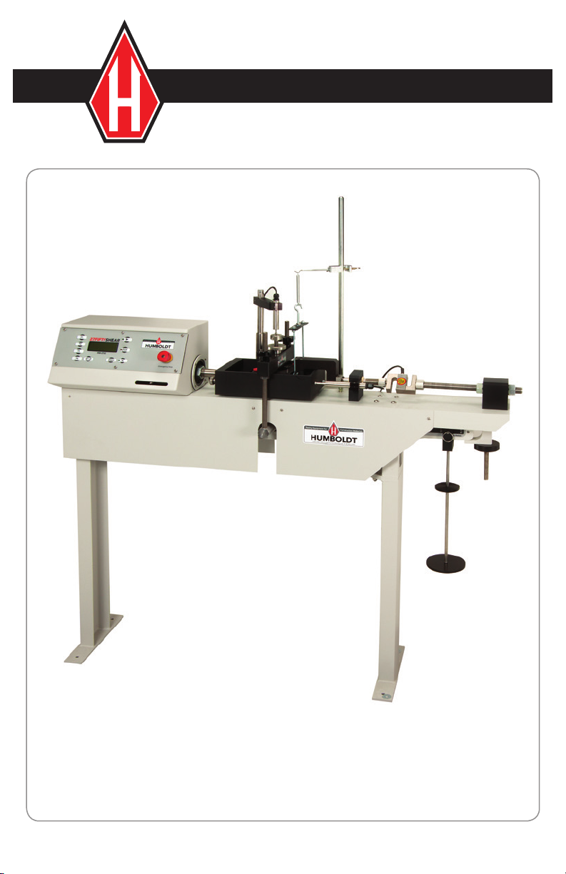
The standard apparatus consists of the following:
A gearbox-driven horizontal screw ram and geared jack upon a rigid
stand and horizontal base. The gearbox and motor are used with the
stepless speed control box.
The control box is situated on the front, to the left of the metal stand.
To avoid the need of calibration charts and to maximize the ease
of desired speed selection, the speed control of the apparatus is
calibrated in inch/min (engineering units), which are indicated digitally.
The main base also incorporates a vertical support bracket, to guide
the spindle of the selected means of reactive measurement of the
applied shear force. (force indicators H-4454.XXX are not included
and must be selected from the Humboldt Mfg. Co. range). There is a
reaction bracket at the rear of the base, against which the load ring or
measurement device is pushed.
The shearboxes are equipped with a carriage mounted on linear ball
races resting upon sliding tracks. When mounted, the carriage is
transversely restrained but is free to glide axially along the centerline
of the geared jack and reaction bracket. Affixed to the geared jack is
the vertically mobile dial gauge arm. The dial gauge arm mounts an
anti-clockwise dial gauge allowing for direct visual measurement of the
consolidation of the sample.
Shearbox squares are not included with the standard apparatus,
though can be purchased separately as an accessory.
The method of normal stress application, on the standard apparatus,
is by a vertical load hanger resting above the soil specimen and
hanging downwards permitting the selected weights to rest upon its
load mount, while traveling with the upper specimen half, (should any
lateral movement take place). The consolidation force is applied to the
specimen proportionally by the amount of weights placed upon the
hanger mount.
The load ring and dial gauges are necessary to perform the shear
testing procedure and are supplied as extras. The shear force is
obtained by the geared jack moving along the axis of the base in an
attempt to move the carriage and the slightly separated halves of
3

the shearboxes. The upper half of the specimen is connected to a
bracket at the opposite side of the geared jack. This bracket requires
a measuring device to provide an opposing force to the upper
shearbox half, affixed to the reaction bracket of the base.
The standard measuring devices are the load ring and dial gauges.
The load rings are of either 2kN or 5kN capacity. Each load ring is
supplied with a dial gauge for measuring deflection in the load ring.
One additional dial gauge is required to measure the displacement of
the upper and lower shearbox halves.
The power ON/OFF switch is located at the rear of the apparatus.
When it is switched “ON” the Liquid Crystal Display (LCD) is
illuminated.
4

Manufacturer’s Rights and Responsibilities
Software Copyright
COPYRIGHT NOTICE
©2005 HUMBOLDT MFG. CO.
All Rights Reserved.
This manual or parts thereof, may not be
reproduced in any form without the expressed written
permission of HUMBOLDT MFG. CO.
UNPUBLISHED LICENSED PROPRIETARY WORK
©2005 HUMBOLDT MFG. CO.
The programmable, read-only memory, integrated circuit package
contained in this equipment and covered with a copyright notice
label contains proprietary and confidential software, which is the sole
property of HUMBOLDT MFG. CO. It is licensed for use by the original
purchaser of this equipment for a period of 99 years. Transfer of the
license can be obtained by a request, in writing, from HUMBOLDT
MFG. CO.
With the exception of HUMBOLDT Authorized Service Facilities you
may not copy, alter, de-compile, or reverse assemble the software
in any fashion except as instructed in this manual. US copyright laws,
trademark laws, and trade secrets protect the materials.
Any person(s) and /or organizations that attempt or accomplish the
above violation or knowingly aid or abet the violation by supplying
equipment or technology will be subject to civil damages and criminal
prosecution.
5

IMPORTANT NOTICE
The information contained herein is supplied without representation
or warranty of any kind. Humboldt MFG. CO. therefore assumes no
responsibility and shall have no liability, consequential or otherwise, of
any kind arising from the use of the described equipment contained in
this manual.
Updated products
The manufacturer reserves the right to change or modify product
design or construction without prior notice and without incurring
any obligation to make such changes and modifications on products
previously or subsequently sold.
Fitness for application
The manufacturer makes no recommendations or claims regarding
fitness for applications other than the specific tests as defined in this
User Guide.
General Warnings
Safety Warnings
Operators should take care to operate this machine under the
maximum load restrictions. The machine is programmed at the factory
to provide safety shutdown if the upper or lower maximum travel is
exceeded.
Electrical Warnings
Typically, there is no reason for the operator to open the machine.
However, if the customer’s engineers attempt to change settings to the
circuit board connected to the back panel, the machine must always be
unplugged before this operation. Unplugging the internal connection to
the back panel circuit board while the machine is under power will
result in permanent damage to the circuit board.
6

Installation and Set-up
Unpacking
Initial inspection should include checking for physical damage during
shipping and obvious external damage to the product.
Package contents are defined by your packing list. Make certain that
the contents of your shipment match the documentation provided by
your packing list.
Setup
1. Unclamp the counterbalance lever-loading arm by undoing the
beam jack.
2. Screw in the consolidation dial gauge arm and associated
pillar to the machine.
3. Place ball races on track.
4. Place carriage assembly on ball races, placing slotted end over
the geared jack.
5. Locate proving ring between bracket and carriage body (the
reaction bracket has a ball socket for clamping) by screwing to
the proving ring threaded blocks, utilizing the adapters provided.
The dial gauge should be compressed to its midway position
(approximately 5mm) by the adjusting screws in the proving ring.
Electrical Connections
Humboldt HM-2750 Series controllers are equipped with an internal,
digital, switching power supply, which allows them to be used with most
power configurations throughout the world. The units are supplied with
an IEC electrical cord with a standard 110V USA plug.
HM-2750 Series Controllers arrive ready for operation. Attach the
controller to top of motor housing with supplied velcro fasteners.
Attach the supplied IEC electrical cord to the machine and plug into a
standard wall receptacle for use in the United States.
For locations other than the U.S., replace the supplied electrical cord
with an IEC cord with the correct plug for your application. The supplied
cord can also be used by cutting the standard plug from the cord and
attaching the correct plug.
7

Instrument Inputs (load cell/transducer connections)
Models HM-2750A and HM-2750D have 4 instrumentation inputs
located on the back panel to accommodate load cell/transducer
connections. This feature allows you to set up and calibrate up to 4
different instruments, which the unit can quickly switch between for
those needing to do multiple tests.
Third-party load cells/transducers, which are compatible, can also be
used with the HM-2750 Series. Compatible units will have an
excitation voltage of 0-10 volts and an output of 0-100 millivolts.
Prior to use all third-party instrumentation mush be configured and
calibrated for use. Please refer to the Configuration and Calibration
sections of this manual.
If you are using third-party cables for transducer connections, make
sure they are wired to be compatible with the HM-2750. Consult
Figure #1 for a compatible reference wiring diagram. Plugs to connect
third-party instrumentation to the Humboldt HM-2750s are available,
order part HM-000474.
Preparation and Loading Procedure
1. Place test samples in carriage and tighten clamp screws on
assembly. Remove the two lock screws from the squares and then
turn down and bring back the two other screws to split the sample.
2. Raise and locate the crossbar on top pad in vertical position, This
verticality is achieved by adjusting the carriage position. Raise
beam jack to hold loading arm so that no load can be applied to
the sample. Add weights to give the necessary stress while the
beam is secured.
3. Locate and fix top screws on crossbar and locate consolidation dial
gauge, (add water at this point). Beam position should be level.
4. Release beam jack and consolidate sample.
5. Shearing preparation:
a. Take up slack by adjusting lock nuts on the reaction bracket.
b. Position strain dial gauge on bracket. (dial gauge should be
fully compressed) .
c. When required, re-select travel direction by switching “S”
button and before operating the “F or R” switch in the
direction of travel, release the direction bracket screw to
take load out of proving ring. The dial gauge in this zero load
condition should be compressed to its midway position.
8

Figure 1. Compatibility wiring diagram for 3rd party cables
Pin3= +dc Output
Pin4= –dc Output
9
Computer Connection
Humboldt HM-2750A and HM-2750D Controllers can be connected
to a PC computer to take advantage of Humboldt’s HMTS software
capabilities, conduct real time data logging and enhanced report
generation. This is accomplished via the RS232 port on the back panel
of the machine (refer to Figures 2 & 3). Use a RS232 cable (supplied)
and attach it between the computer’s RS232 port and the MiniLogger.
The minimum compatible computer configuration is a PC with Pentium
III 550 MHz processor, 512 MB of RAM and a 40GB hard drive running
Windows®XP Professional system software.
Additional Device Connection
Additional devices, such as additional HM-2750s and/or HM-3000 Load
Frames, MIniLoggers, and other computer-compatible load frames can
be connected to a computer via the RS-485 port on HM-2750A and
HM-2750D models. This allows you to daisy-chain several devices to
the same computer. Use a standard CAT 5 cable (not included) to link
the additional device’s output port to the HM-2750’s RS-485 input port
(refer to Figures 2 & 3). Dip switches and rotary switch need to be set to
primary or secondary usage (see Figure 5).
Analogue Device Connection
Humboldt MiniLoggers can be set up to output directly to a chart
recorder to provide a hard copy printout of test results. To accomplish
this, connect your chart recorder via cable attached to the HM-2750’s
analogue port on the back panel of HM-2750 A or D controllers
(see figure 7).

10
Figure 3. Rear panel of MiniLogger showing Analog Port, RS232 Port,
RS-485 Input and Output and the four instrumentation channel
inputs.
69
51
sweepreset not
connected
CH3CH4 CH1CH2
D-SUB, 9-PIN MALE
ANALOG PORT ACCESS
Cable configuration for
analogue port access.
Pins 1, 2, 3 & 4
(Reserved for
Humboldt Chart
Recorder)
Figure 2A. Rear panel of
HM-2750A showing the four
Analogue instrumentation
channel inputs, the Analogue
Port, RS232 Port, RS-485
Input and Output, the On/
Off Switch and the motor
cable input.
Figure 2B. Rear panel of
HM-2750D showing the
four Digital instrumentation
channel inputs, the Analogue
Port, RS232 Port, RS-485
Input and Output, the On/
Off Switch and the motor
cable input.
Figure 2C. Rear panel of
HM-2750 showing the
On/Off Switch and the
motor cable input.
HM-2750D
HM-2750A
HM-2750

11
Figure 4. Diagram illustrating computer and multiple device connections.
USB to RS-485
HM-000379

Operation
Power Switch
The Power Switch is located in the back panel on the rear of the
HM-2750 controller above the electrical cord inlet. Also, located
between the electrical cord inlet and the Power Switch is the Fuse
Compartment. Humboldt HM-2750s use a 10 amp fuse. To begin
operation, press the Power Switch.
Figure 6. HM-2750 Power Switch, Electrical Cord Inlet and Fuse
Compartment.
12
Fuse Compartment.

Figure 5. HM-2750 Series Front Control Panel
Key Functions
13
Set Up Key
Pushing the Set Up Key brings up the main set up screen
from which you can run a test, review your last test, access
the engineering set up menus and set the date, time,
units, standards criteria. This key also is used to return to a
previous screen.
Speed Key
Pushing the Rate Key allows you to change the selected
platen speed between 0.00001 and 0.499999 inch/min.
Stop Key
Pushing the Stop Key stops the machine.
Forward Key
Pushing the Forward Key moves the shear box to the right.
Also, by holding down the Key, the machine will move
forward at the fast rate of 0.5 in/min. Releasing the key
changes the machine's speed back to its set rate.
Reverse Key
Pushing the Reverse Key moves the shear box to the left.
Also, by holding down the Key, the machine will move in
reverse at the fast rate of 0.5 in/min. Releasing the key
changes the machine's speed back to its set rate.
SPEED
STOP

Function Keys
The four function keys are used to navigate through the
MiniLoggers’ menu-driven display. The function keys
correspond with the command lines on the menu display.
F1 corresponds with the first command line; F2, the
second, etc. Command lines that are active in any display
will be proceeded by an (*). If no (*) is present, the
corresponding function key is not active.
14

Set-up Functions (all models)
Set Date
To set the Date press until you see this screen:
Press (SET DATE/TIME/UNITS/STND). You should see this screen:
Press (SET DATE). You should see this screen:
Press (DATE) to select the month/date/year. Press
(INCREASE) or Press (DECREASE) to change the appropriate
number.
To return to any prior screen you can always press
Set Time
To set the Time press until you see this screen:
* REVIEW LAST TEST
* RUN TEST
* ENGINEERING SETUP
* SET DATE/TIME/UNITS/STND
* SET DATE
* SET TIME
* UNITS = ENG/METRIC
DATE = “MM/DD/YY”
* INCREASE
* DECREASE
* REVIEW LAST TEST
* RUN TEST
* ENGINEERING SETUP
* SET DATE/TIME/UNITS/STND
15

16
Press (SET DATE/TIME/UNITS/STND). You should see this screen:
Press (SET TIME). You should see this screen:
Press (INCREASE). or Press (DECREASE) to change the
appropriate number.
To return to any prior screen you can always press
Set Units
To set the Units the HM-2750 will use to display results, press
until you see this screen:
Press (UNITS) to toggle between English and Metric Units.
Select the units desired—the flashing units are the active choice.
To return to any prior screen you can always press
* SET DATE
* SET TIME
* UNITS = ENG/METRIC
TIME = “HH/MM/SS”
* INCREASE
* DECREASE
* SET DATE
* SET TIME
* UNITS = ENG/METRIC
* STANDARD = ASTM/BS

17
Set Standards
To set the Standards the HM-2750 will use, press until you see this
screen:
Press (SET DATE/TIME/UNITS/STND). You should see this screen:
Press (STANDARD) to toggle between ASTM and BRITISH
STANDARD.
Select the standard desired—the flashing standard is the active choice.
To return to any prior screen you can always press
* REVIEW LAST TEST
* RUN TEST
* ENGINEERING SETUP
* SET DATE/TIME/UNITS/STND
* SET DATE
* SET TIME
* UNITS = ENG/METRIC
* STANDARD = ASTM/BS
Rate (Motor Speed Adjust)
To set the speed of the HM-2750 press
SPEED
You should see this
screen:
Press (SPEED) to move between the numbers. Keep pressing
until the digit you want to change is flashing. Once you have
selected the number you want to change, press (INCREASE) or
(DECREASE) to change the number to the desired value. Once
you have set the speed, press the or to activate it.
MOTOR SPEED ADJUST
* SPEED = “X.XXXX”
* INCREASE
* DECREASE

18
Channel Configuration (Models A and D only)
If you are adding new instrumentation, changing existing
instrumentation or reconfiguring the HM-2750’s channel setup, you
need to configure the channel for use with the devices you have.
To configure a channel, press You should see this screen:
Press (ENGINEERING SETUP). You should see this screen:
Press (CONFIGURATION) You will be asked for a password, enter:
You should see this screen:
Press (SELECT CHANNEL) to scroll through and choose the
channel you wish to configure. Once you have selected a channel press
(CONFIGURE CHANNEL). You should see this screen:
* REVIEW LAST TEST
* RUN TEST
* ENGINEERING SETUP
* SET DATE/TIME/UNITS/STND
* CONFIGURATION
* CALIBRATION
* SAMPLING INTERVAL
* MANUFACTURES INFO
CONFIGURATION screen
* SELECT CHANNEL “CH1”
* CONFIGURE CHANNEL
* CONFIGURE TEST
“CH1” CONFIGURATION
* NAME = “CH1”
ENG MIN = 0
* ENG MAX = “VALUE”

19
Naming Channel (Models A and D only)
From the previous screen, shown above, Press (NAME) to select
the name you wish to change, press the key until the name you wish to
change is indicated. You should see this screen:
Press (INCREASE) or (DECREASE) repeatedly to scroll
through the available channel names for an appropriate choice. Choices
for channel names are: CH1, CH2, CH3, CH4, LOAD1, LOAD2, LOAD3,
LOAD4, DISP1, DISP2, DISP3, DISP4, FLOW, STAB, PRES1, PRES2,
PRES3, PRES4, VOLU1, VOLU2, VOLU3 and VOLU4.
NOTE: It is important to assign an appropriate name when naming
channels because the HM-2750 Series controller will choose a unit
of measure based on the name assigned. For example, if you are
configuring a load cell, name the channel Load 1, 2, 3 or 4. This
will ensure that the channel reads in lbs (kN). The same applies to
Displacement (DISP 1, 2, 3 or 4) reading in in/mm and Pressure (PRES1,
2, 3 or 4) reading in psi (kPa).
Once a name has been chosen for a channel Press to return to the
previous screen. You should see this screen:
(LOAD1 was chosen as name):
“CH1” CONFIGURATION
* NAME = “CH1”
* INCREASE
* DECREASE
“CH1” CONFIGURATION
* NAME = “LOAD1”
* ENG MIN = 0
* ENG MAX = “VALUE”
This manual suits for next models
3
Table of contents
Other Humboldt Test Equipment manuals

Humboldt
Humboldt HM-5470.3F ConMatic IPC User manual

Humboldt
Humboldt ConMatic IMC User manual

Humboldt
Humboldt H-4212MH User manual

Humboldt
Humboldt H-4165 User manual

Humboldt
Humboldt HS-4157 User manual

Humboldt
Humboldt HM-4100A User manual

Humboldt
Humboldt HM-2850.3F User manual

Humboldt
Humboldt Digital MasterLoader HM-3000.3F User manual

Humboldt
Humboldt HM-5760.3F User manual

Humboldt
Humboldt HM-5030 User manual