Fälglås och pumpa däck:
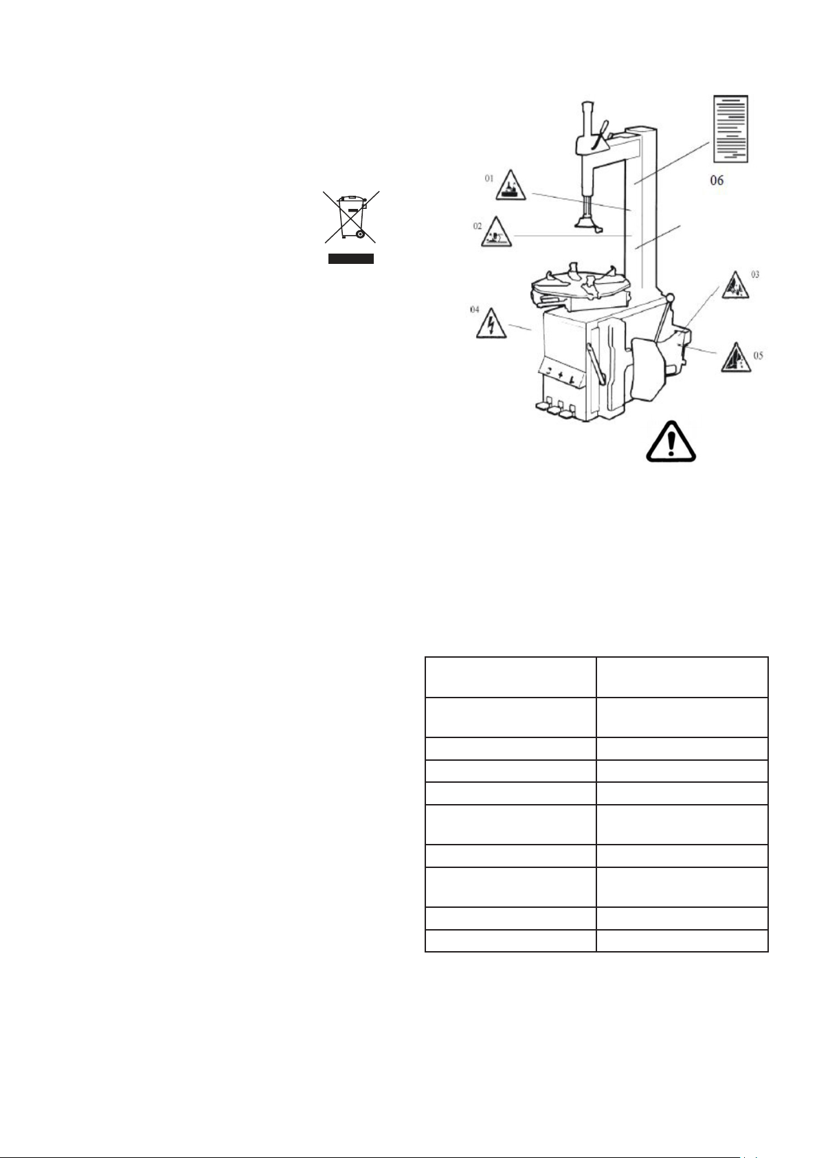
Varning! Däck kan explodera på grund av följande:
1. Fälgen och däcket är inte av samma storlek.
2. Däcket eller fälgen är defekt.
3. Däcktrycket är över max. tryck rekommenderat
av tillverkaren.
4. Operatören misslyckas med att följa
säkerhetsföreskrifterna.
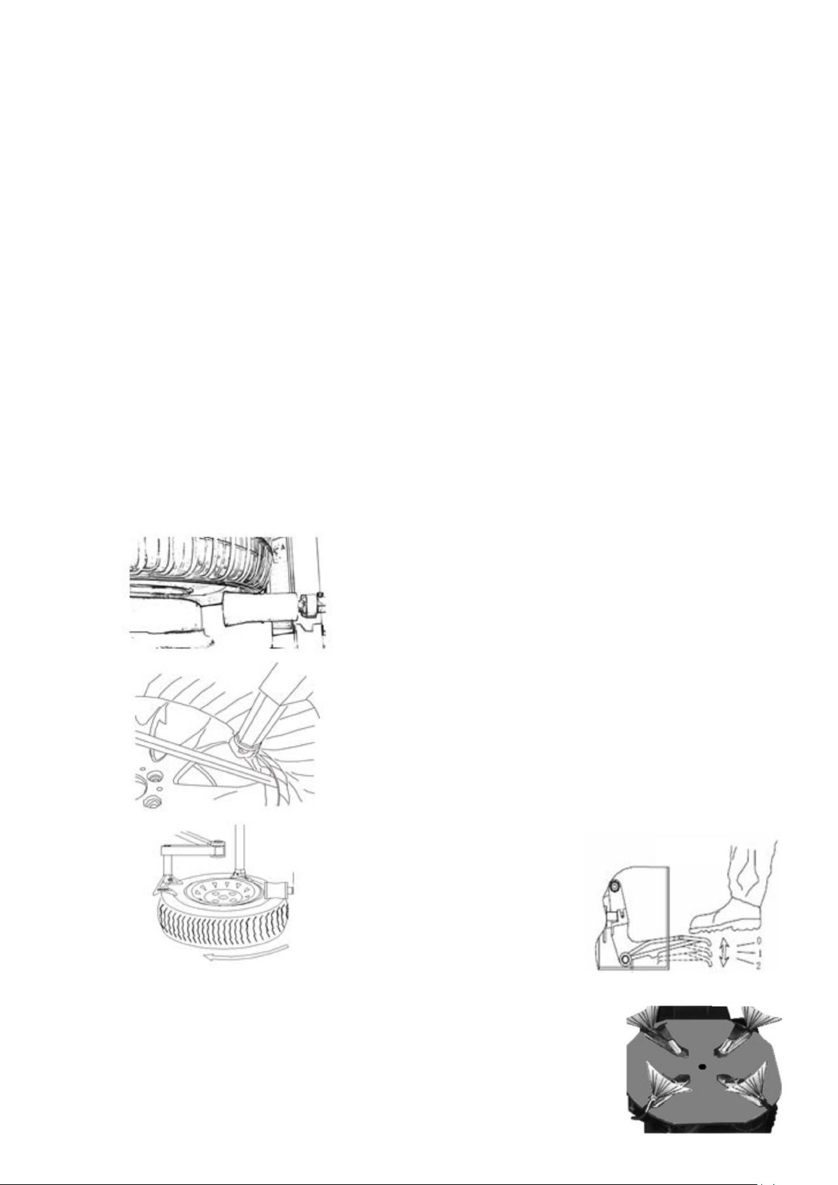
uppblåsningshuvudet ska ge luft.
b). Tryck pedalen hela vägen ner (Fig 17,
position 2), en stark luftstöt ska komma från
hålen i de fyra hakarnas låsreglage. (Fig 18)
Pumpa däcket
Kontrollera att däcket är i gott skick och se till att
det inte nns några skador innan pumpningen
påbörjas. Håll händerna och kroppen så långt ifrån
däcket som möjligt. Montera ventilkärnan om den
tagits ur. För att pumpa däcket, anslut
luftpåfyllarens munstycke till däckets ventilskaft.
Se till att luftpåfyllarens munstycke blir helt
nedtryckt över ventilskaftets gängor. När
luftpåfyllarens munstycke är på plats, lås fast det
på ventilskaftet genom att släppa låsanordningen.
Så snart däcket har uppnått rätt däcktryck, lossa
luftpåfyllarens munstycke från ventilskaftet och
skruva på ventilhatten. Däcket pumpas med
korta pumpningar, samtidigt som man kontrollerar
däcktrycket.
Notera:
1. Underlåtenhet att följa alla varningar och
instruktioner kan leda till allvarlig personskada
eller dödsfall för operatören eller medhjälpare.
Överstig aldrig 3,5 bar (50 psi) vid fastsättande
av klinch eller uppblåsbara däck.
2. Om ett högre däcktryck är nödvändigt, ta av
hjulet från däckväxlaren och fortsätt
uppblåsningsförfarandet med hjulet inuti en
speciell skyddskåpa. Överstig aldrig det
maximala lufttrycket som däcktillverkaren
anger.
3. Endast specialutbildade personer får utföra
dessa operationer. Låt inte andra använda eller
vara nära däckväxlaren.
Flytta maskinen
Använd gaffeltruck för att ytta maskinen. Koppla
från däckväxlaren från elnätet och den
pneumatiska luftförsörjningen, lyft basplattan och
sätt i gaffeltruckarnas fötter. Montera sedan
däckväxlaren till en ny position och xera den
ordentligt.
Obs! Den plats som valts för att xa däckväxlaren
måste uppfylla säkerhetsföreskrifterna.
Underhåll
Varning: Endast
professionella personer kan
göra underhåll. För att
förlänga maskinens liv
underhåll maskinen noggrant
enligt bruksanvisningen.
Annars kommer det att
påverka tillförlitligheten hos
maskinen eller till och med
skada operatören och andra i
närheten.
Varning: Innan du utför underhåll, koppla från
däckväxlaren från elnätet, strömförsörjningen och
den pneumatiska luftförsörjningen, och tryck ner
hakarna så att de är öppna och stäng
monteringsbordets pedal. Trampa 3 ~ 4 gånger för
att evakuera all tryckluft från maskinen. Skadade
delar måste bytas ut av professionella personer
med reservdelar som tillhandahålls av tillverkaren.
• Rengör maskinen en gång varje dag efter
arbetet. Rengör smuts på monteringsbordet
med dieselolja en gång per vecka och smörj
glidorna och klämmorna.
• Efterföljande
underhåll måste
ske minst en
gång per månad:
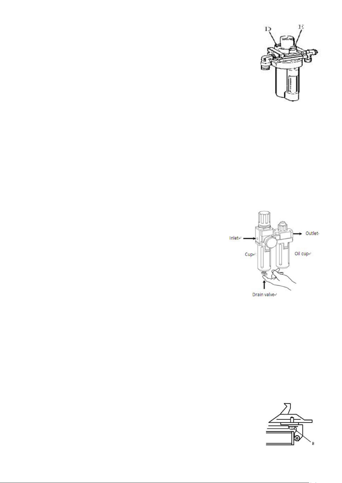
Kontrollera
oljenivån i
oljemattningsmaskinen,
fyll på med SAE30 # olja
om det behövs. Skruva av
med insexnyckel (E).
Baserat på anslutning av tryckluft, tryck först
upp hakarna och trampa på pedalen till
monteringsbordet 5-6 gånger, och kontrollera
om olja faller ner i oljebägaren. För kontinuerlig
drift, tryck två gånger varje gång, släpp ner ett
oljedropp, i annat fall justera skruven (D) som
kontrollerar att oljan går in
(Fig 19).
• Som visas i Figur 19-1, när du funnit att det
nns lite vatten i koppen, tryck upp
dräneringensventilen för att tömma vatten med
ngrarna. Släpp ngret efter att du dränerat
vattnet, dräneringsventilen stängs automatiskt.
Obs! Efter de första 20 dagarna
ska du dra åt hakarna med
åtdragningsskruvarna (B) på
monteringsbordet (Fig 20).
Fig 19
Fig 19.1