Leica SP8 User manual

Leica SP8 inverted confocal microscope November 18,2019
•System description:
•DMi8, inverted microscope: BF, Fluo (blue, green, red)
•BF TL Detector (transmitted light image, no additional illumination or time)
•Scanning stage with z-Galvo and Navigator (overviews, selection of regions of
interest,…)
•Scanner with Scanfield Rotation
•2 PMT detectors (photo multipliers)
•1 Hybrid Detector normal (more sensitive and no detector noise nor background)
•1 Hybrid Detector SMD (fast, for FLIM, FALCON)
•Laser lines: 405, White Light Laser (470-670nm, up to 8 laser lines simultaneously)
•FALCON including Pulse Picker for WLL
•LIGHTNING (Deconvolution) for Superresolution and super sensitive imaging
•Objectives:
•Objective PL FLUOTAR 10x/0.30 (overview)
•Objective PL APO 20x/0.75 dry CS2
•Objective PL APO 20x/0.75 IMM Corr CS2 (Oil, water, glycerol, silicon oil)
•Objective PL APO 40x/1.20 Water Corr CS2
•Objective PL APO 63x/1.30 Glycerol Corr CS2
•System Start Up
•Switch on ‘PC-microscope’ button (1). Gives power on the computer and microscope
controller
•Switch on ‘scanner power’ (2)- enables the scanning head
•Switch on ‘Laser power’ (3)
•Turn the key (4) in position ‘on’- enables Laser shutters
•Switch on fluorescent lamp(5) for visual examination
•(if temperature control needed) switch on the temperature controller (6). Set up
temperature for the heating stage (port 2) and objective heater (port 1)
!!!!!! If you are not using Z-galvo stage, always place it UPSIDE DOWN on the
optical table
•For imaging: start LAS AF software. Select configuration Machine.xlhw and DMI8
microscope (default). Load of "Standard" settings possible (Fig.1)
•!!!!! Never use "Use last system settings"
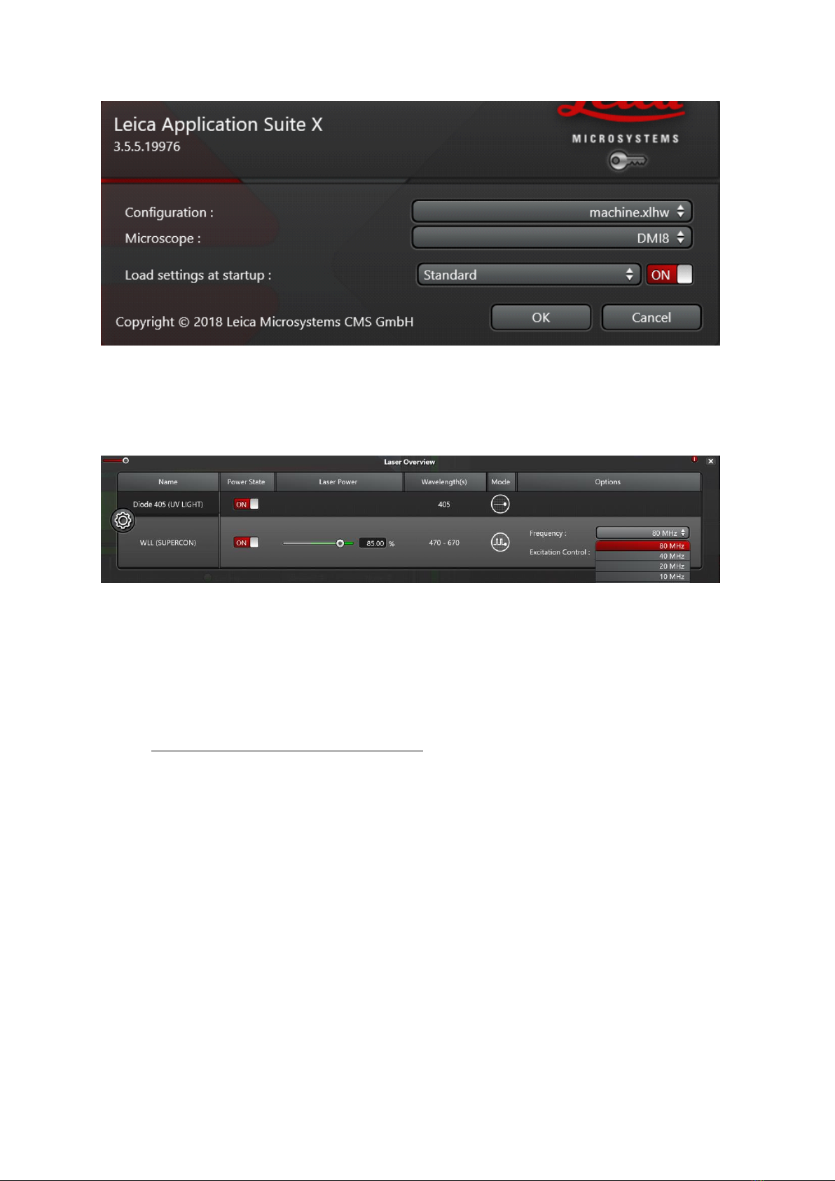
Fig.1
•In the LAS AF software, go to ‘configuration’ –‘lasers’- select the lasers you want to
use. Default Laser power of the WLL is 85%
Fig.2
•make sure the pulse picker is set to 80 mHz, otherwise laser power is significantly
lower (Fig.2)
•Visual examination of the sample
•On the microscope touchpad choose the illumination icon to open the illumination
menu
•for transmitted light press the BF button and operate the TL shutter
•small intensity wheel is found on the left side of the microscope (TL indicator light is
next to it)
•For fluorescent illumination, press FLUO button in the illumination menu of the
microscope touchpad
•Choose filter cubes on the front panel: (DAPI, RHOD, LED_470). Open the IL-shutter
to see fluorescence
•small intensity wheel (same as for BF) on the left side of the microscope stand lets
you change the LED intensity
•FOCUS on your sample !!!
•Visual illumination is disabled during scanning, the system is automatically changing
to "CS" combi mode
•Acquiring confocal images
Before you start:
Make sure that the Autosave option is switched off in Open Project !!!
CHECK IF THE HyD SMD 1 DETECTOR COOLING CONTROL LAMP IS GREEN. IF IT'S RED
DON'T USE IT !!! CONTACT OUR BIF TEAM IMMEDEATELY !!!
•Acquisition mode: xyz
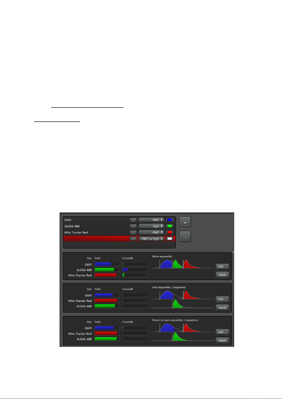
•The easiest way to plan your confocal imaging is using the dye assistant (Fig.3). Open
the menu and enter your fluorophores. Choose PMT or HyD detectors accordingly.
Then choose offered imaging methods (simultaneous and/or sequential scanning
according to your needs considering cross talk and imaging speed. Press "Apply"
Fig.3

•The system is turning on laser lines (tunes to the excitation maxima of selected
dyes), activates detectors with appropriate bandwidth and shows the emission
spectra of selected dyes.
•Switch on T-PMT if needed for transmitted light imaging.
•Press “Live” to get an image preview
•Laser power, detector bandwidths and Detector gain may be adjusted
Fig.4
Sep your confocal image:
!!! Note: gain, offset, scan field rotation, pinhole, zoom, z-position settings may be changed
via the control panel in front of you
Position your sample:
change the zoom or rotate your image
Adjust the image format:
press Nyquist button for proper sampling
Adjust the pinhole:
Changes will alter the confocal section thickness
And the SNR of the image ; default is AU 1
Adjust your Signal to Noise ratio (SNR):
apply frame or line averaging, reduce the scan speed
check the pixel dwell time
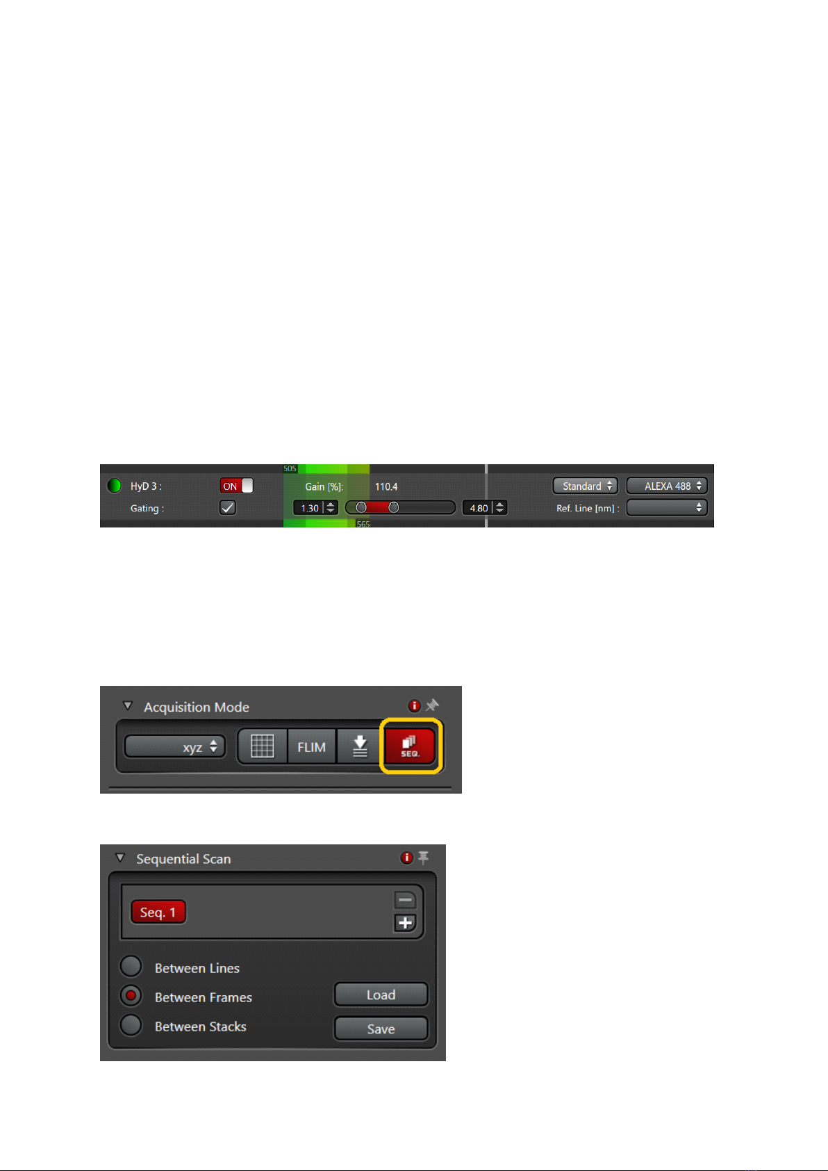
•Gated detection
Note: Only possible using HyD detectors!!!
•used to reduce auto fluorescence or reflection with shorter lifetimes than actual
fluorescence
•activate gating Fig.5
•choose the detection window in ns for your fluorophore, adjust during live scan
•Setting up sequential scan
•Select ‘seq’ symbol in the ‘acquisition mode’ menu

•select line, frame or stack sequential
•Set up first configuration
•ATTENTION!!! in line sequecial only PMTs and Lasers are switched on/off between
the lines (laser shutters, detector bandwidth remain the same, NO HARDWARE
MOVEMENT between lines is possible !!!
•Press ‘+’. Set up next configuration, and so on. Set optimal imaging conditions for
each configuration.
•You can save "sequential files" in your folder and load them again.
•Setting up a Z-stack
•only use ‘Z position’ knob on the control panel in front of you!!!
•Acquisition mode xyz
Fig.6

Select ‘Z-galvo’ or z-Wide in the ‘Z-stack’ menu
Start scanning with ‘live’.
Use ‘Z position’ on the control panel, select the first slice.
Press ‘begin’ in the Z-stack menu. Move focus up with ‘Z position’, select
the most superficial slice, press ‘end’.
Set up Z-step size according to your needs
activate system optimized for Nyquist settings according to the objective
and pinhole settings used
to capture Z-stack, press ‘start’. The Z-stack will be stored in projects
•Setting up time series:
•Acquisition mode xyt or xyzt
Fig.7
•To estimate minimal interval, activate ‘minimize’ in ‘t’ menu
•Or set your own time-lapse interval (should exceed the minimal)
•Select experiment duration or number of frames

•Press ‘Apply’
•To start time series, press ‘start’
•Tile Scan
See the manual for Navigator module on the desktop
•Saving your data
•go to “Open projects” menu
•Save your data directly to DATAINT (E) on the computer or in your external file
server
•PLEASE NOTE: All data on our E drive are deleted after 30 days automatically!!!
•Autosave option in “Open Projects” menu :
Fig.8
•switch “Auto save option” ON
•rename your project
•choose destination folder
•rename your image
•Acquiring confocal images using the Lightning –Deconvolution
environment
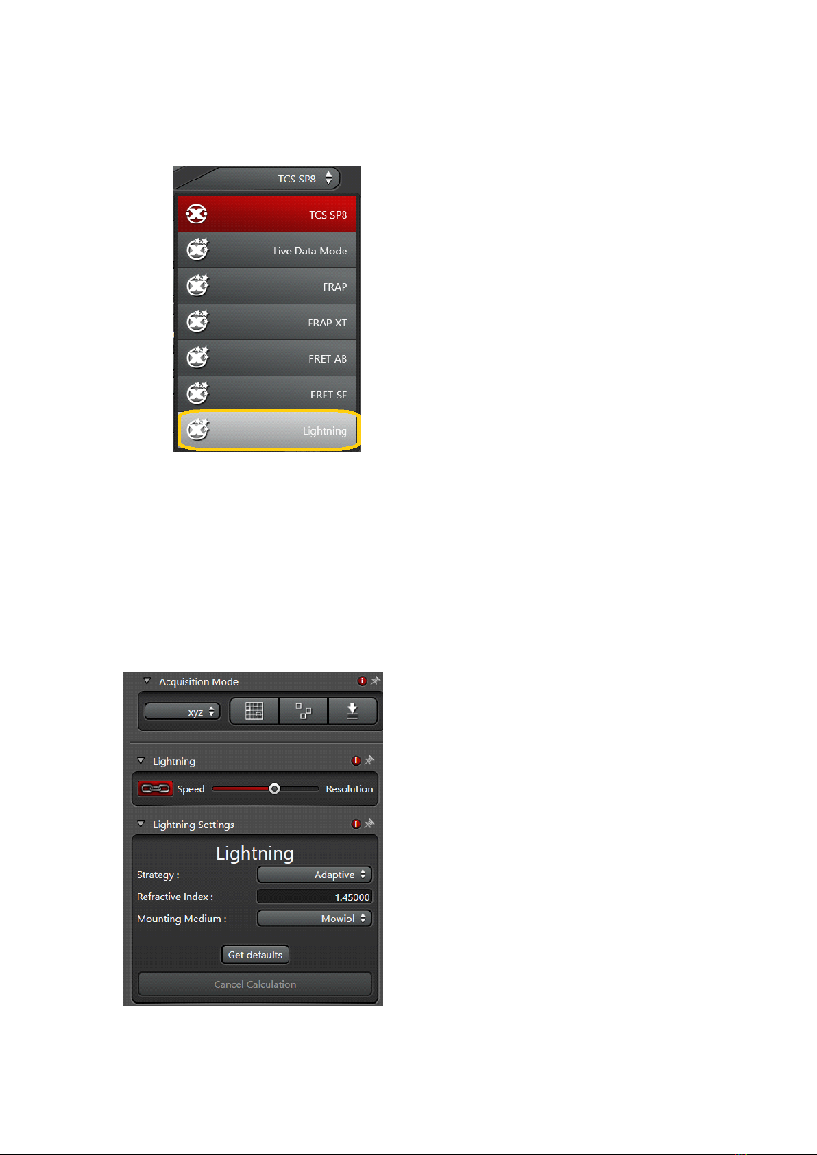
Fig.9
•Choose Lightning option from the drop down menu (Fig.9)
•The Lightning slider (Fig.10) controls the deconvolution strength by acting on
imaging parameters such as:
Pixel size, scan speed, number of averages, pinhole settings
Fig.10

•Select your deconvolution Strategy: Adaptive or Global
!!! Note: In the Adaptive setting Background and bright pixels are treated
differently which might lead to un-linearities in your result (may create problems
in quantitative measurements). The Global method is treating every pixel in the
same way!!!
•Put in the embedding medium that you have used for your sample preparation
Fig.11
•To change factory deconvolution settings, go to Configuration, Lightning Tab
(Fig. 11)
•We recommend to use pinhole 0.6 AU and oversampling of 1.7
•Save your new settings under a different name and load them for imaging
•Set up your experiment, press start
•The deconvolution will start immediately online, when you have started your
experiment
•Raw data and deconvolved image will be saved as separate files in Open project
•Deconvolution processing after imaging in standard mode
•Images taken in the regular confocal environment may be deconvolved
afterwards
•select the image in Open project, then go to the Process menu→Lightning
•put in your parameters and press “Apply”
Other manuals for SP8
3
Table of contents
Other Leica Microscope manuals


