LEILA
DF£00
Compound
Microscope
Service
Manual
Table
of
Contents
Section
Page
1.0
Introduction
ss
2
2.0
Coarse
Adjustment
Knob
Replacement
...........................
4
3.0
Fine
Adjustment
KnobReplacement.......................
4
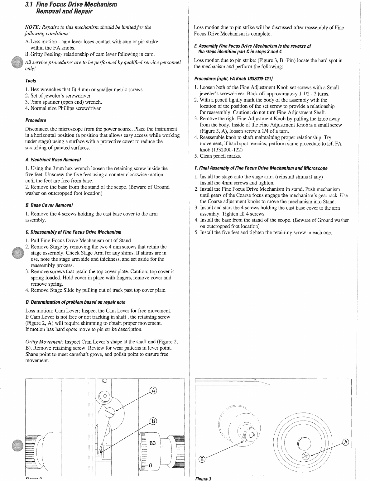
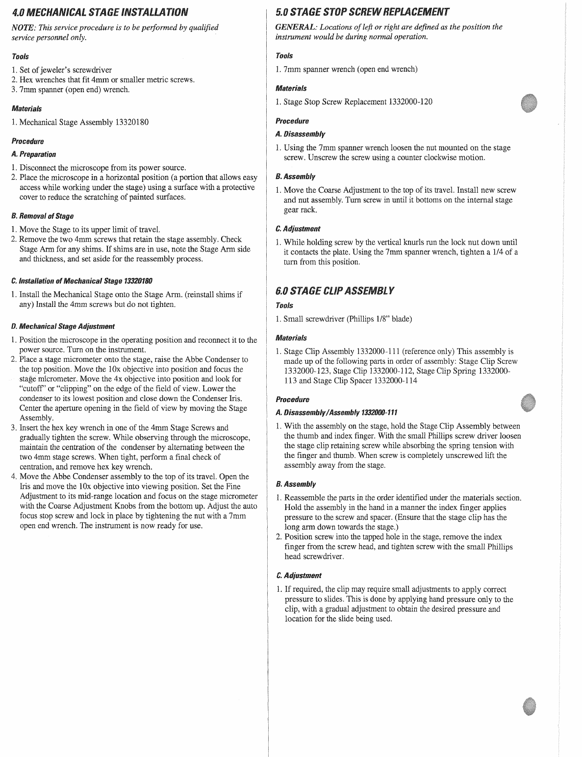
3.1
Fine
Focus
Drive
Mechanism
Removal
and
Repair
........
5
4.0
Mechanical
Stage
Installation
sismo
6
5.0
Stage
Stop
Screw
Replacement
n
6
6.0
StageClipAssembiy......................
een
6
7.0.
Abbe
Condenser
Replacement.............
i
7
8.0
Foot
Removal
and
Replacement
................
n
7
9.0
Microscope
ElectricalCordRemoval..............................
7
10.0.
Lamp
Removal
and
Replacement
pps
7
11.0
LampBallastTransformerRemoval...............................
8
12.0
FuseRemovalandReplacement...............................
8
13.0
On/Off
Switch
Removal
and
Replacement
.....................
8
14.0
Removal
and
Installation
of
Binocular
Body
...................
8
15.0
Removal
and
Installation
of
MonocularandTeachingBody...................................
9
1.0
INTRODUCTION
The
LEICA
BF200
Compound
Microscope
is
designed
specifically
for
student
use
in
secondary
schools.
High
quality
glass
optics
and
a
variety
of
accessories
make
the
BF200
Compound
Microscope
the
ideal
choice
to
meet
diverse
applications.
_Contact
your
local
Leica
Representative
for
more
information,
questions
or
parts
ordering.
NOTE:
All
service
is
to
be
performed
by
qualified
service
personnel
only.
Explanation
of
Warning
Symbols
==
CAUTION:
Replace
with
same
type
and
rating
fuse
5x20
Type
T
Rated
250mA
T/250V
A
CAUTION:
Risk
of
7
CAUTION:
(Refer
to
4
electric
shock
accompanying
documents)
Part
#
13320010
13320020
13320030
13320050
13320040
1332000-124
13320060
1332000-125
13320070
13320080
13320090
13320100
13320110
1332000-127
13X54242
1332000-120
1332000-119
1332000-121
1332000-122
1332000-126
13320120
13320130
13320150
13320300
13320160
13320260
13320270
13320280
13320290
1332000-111
13320180
1332000-130
1332000-116
1332000-117
13320190
13WHDL30015
13WFAG20044
13WSWT20024
1332000-118
13WXFM24023
13313529-606
I3WXFM24024
120V,60HzlampBallast.............................
13313540-127
Description
10xEyepiece.............................
e
10xEyepiece
withpointe.................................
1
15x
Eyepiece
........
iena
Monocular
Body
i
(includes
Monocular
Body
and
Eyepiece
Locking
Screws)
BinocularBody.................................
3
Binocular
Body
Thumb
Screw
...........
4
Monocular
Teaching
Body
eee
5
(includes
Monocular
Teaching
Body,
and
Eyepiece
Locking
Screws)
Eyepiece
Locking
Screws
er
6
Stand/120V,
Abbe
Condenser
and
Fluorescent
..
7
Lamp
(does
not
include
objectives
or
Body)
Stand/230V,
Abbe
Condenser
and
Fluorescent..
7
Lamp
(does
not
include
objectives
or
Body)
Stand/120V,
Disc
Diaphragm
and
Fluorescent
..
7
Lamp
(does
not
include
objectives
or
Body)
Stand/230V,
Disc
Diaphragm
and
Fluorescent
..
7
Lamp
(does
not
include
objectives
or
Body)
Stand,
Disc
Diaphragm
and
Mirror
Illuminator
.
7
(does
not
include
objectives
or
Body)
Coarse
Adjustment
Shaft...
8
Monocular/Teaching
Body
Set
Screws
..............
9
Stage
Stop
ScreW.....................
eee
10
Coarse
Adjustment
Knob
Assembly
................
11
(includes
washer,
set
screws,
lock
screws,
circular
disc
and
plastic
knob)
Fine
Adjustment
Knob
Assembly-Right-
Graduated
(includes
set
screws)
Fine
Adjustment
Knob
Assembly-Left............
(includes
set
screws)
Fine
Focus
Assembly
(with
fine
focus
knobs)
14
4x
Achromatic
Objective
„eee
15
10x
Achromatic
Objective
„eee
15
40x
AchromaticObjective.............................
15
60x
AchromaticObjective..............................
15
100x
Achromatic
Objective............................
15
4xSemi-PlanObjecüve.................................
15
10x
Semi-PlanObjective...............................
15
40x
Semi-Plan
ODjJective
............
и
инииниииининия
15
100x
Semi-PlanObjecüve..............................
15
Stage
Clip
Assembly
........
ri
16
(includes
clip,
screw,
spring
and
spacer)
MechanicalStage
........................................
17
(includes
Slide
Holder
Assembly)
SlideHolderAssembiy....................................
18
Abbe
Condenser
Assembly
..............
19
(includes
Iris
Assembly)
Iris
Assembly
eenennnn
Fluorescent
LAMP
ee
Lamp
Socket...
せ
…
せ
…
せ
eo
Fuse
ii
On/Off
Switch
ee
Rubber
foot...
ss
230V,
50Hz
Lamp
Ballast.........
inn
230V
Electrical
Cord
eee
(with
strain
relief,
3
terminals
and
plug)
120V
Electrical
Cord
eee
(with
strain
relief,
3
terminals
and
plug)