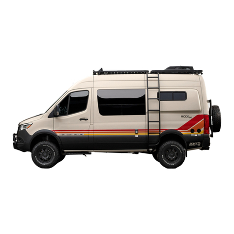
Leisure UNITY 2023 User manual

2023 MANUAL
REAR LOUNGE


MODEL SPECIFIC MANUAL TABLE OF CONTENTS
REV September 22, 2022 i
TABLE OF CONTENTS
1. INTRODUCTION
Supplemental Manual 11
Motorhome Information Kit 12
Options and Equipment 12
Service Assistance 12
Reporting Safety Defects 13
2. GENERAL INFORMATION
Floor Plan 21
Exterior Equipment Location 23
Beds and Seating 25
Rear Lounge 25
RL Front Bed (Optional) 27
TV Location 28
3. SCHEMATICS
Electrical 41
12 volt Electrical Reference 41
120 Volt Electrical Reference 42
Electrical Schematic 43
Plumbing 49
Water lines schematic 49
Drain line schematic 410
Entertainment 411
Satellite Pre-wire 412


MODEL SPECIFIC MANUAL 1. INTRODUCTION
REV September 22, 2022 11
1. INTRODUCTION
Congratulations! Thank you for selecting a Leisure
Travel Vans Motorhome.
Welcome to the exciting world of motorhome travel
and camping, with all the comforts of home with you,
while you travel and enjoy the outdoors.
Your motorhome has been designed and manufactured
to enhance your travel and camping experience and
to provide you with safe, ecient and trouble-free
operation.
Before your first drive, become familiar with the
operation of the vehicle chassis and all functions and
operations of the motorhome. Spend adequate time
with your dealer when you take delivery to learn all
you can about your new motorhome.
SUPPLEMENTAL MANUAL
This manual was prepared to aid the operator and
occupants in the operation and care of the motorhome
by giving specic information about your model. There
are many options to Leisure Travel Vans, so ensure
that you are familiar with your motorhome’s systems
and equipment. All operators and occupants of the
motorhome should read, understand and follow
the instructions in this manual, the vehicle chassis
manual &the information contained in the Motorhome
Information Kit provided with your new motorhome.
Your motorhome contains a number of systems,
components, equipment, and appliances manufactured
by vendors that supply components for Triple E RV.
These vendors are unrelated to Triple E RV.
Before operating the motorhome for the rst time –
even if an experienced motorhome operator – read
and become familiar with all of the relevant manuals
to your motorhome, components, equipment and
appliances provided in the Motorhome Information
Kit. Your familiarity with the detailed operation of
your motorhome will assist in your safe, ecient and
trouble-free motorhome operation.
KEEP the Motorhome Information Kit within your
motorhome for readily available reference.
PASS this manual, the Chassis Operation Manual and
the Motorhome Information Kit to any subsequent
operator or owner.
For clarication or further details on any ofthe enclosed
information, please contact:
Your Leisure Travel Vans Dealer orTriple E RV Customer
Service at:
Email: info@tripleerv.com
Toll Free: 8779929906
Telephone: 2043254361
Fax: 2043255241


1. INTRODUCTION MODEL SPECIFIC MANUAL
12 REV September 22, 2022
MOTORHOME INFORMATION KIT
The Motorhome Information Kit includes but isn’t
limited to information on the components, equipment
and appliances listed below (based on options
selected).
•Refrigerator
•Stove top
•Furnace
•Electrical Panel
•Toilet
•Water Heater
•Water Pump
•Water Filtration
•Vent (roof)
•Fire Extinguisher
•Smoke Detector
•Thermostat
•CO Detector
•Propane Detector
•Gas Regulator
•TV Antenna
•TV/DVD
•Chassis
•Air Conditioner
•Generator
•Stabilizers/Leveling Jacks
•Rear View Monitor
•Inverter
•Entertainment System
•Safety
•Flooring and Countertops
•Electric Step
•Solar Panel
•Surge Protector
•Safe
•Awning
OPTIONS AND EQUIPMENT
Leisure Travel Vans are available in various sizes
and floor plan configurations and with differing
optional equipment. The equipment, accessories and
components described in this manual may not apply
in all respects to your motorhome. Read the material
and manuals provided in the Motorhome Information
Kit for detailed instructions regarding the equipment
specic to your motorhome.
SERVICE ASSISTANCE
Your dealer will assist you with any additional
information you need and will answer any questions
you have about the operation of your motorhome.
When it’s time to service the vehicle, remember
that your dealer knows your motorhome best and is
dedicated to your satisfaction. Your dealer will provide
quality maintenance and assistance during your period
ownership. Triple E RV strongly recommends that you
follow a regular maintenance schedule to keep your
motorhome functioning at its best.
Call the following numbers if you require warranty
assistance while traveling:
Triple E RV: 1-877-992-9906
Canada Sprinter Customer Service:
1-800-387-0100 www.thesprinter.ca
US Sprinter Customer Service:
1-877-762-8267 www.mbsprinterusa.com
Canada Ford Customer Service:
1-800-565-3673 www.ford.ca
US Ford Customer Service:
1-800-392-3673 www.ford.com
Emergency Roadside Service* Call:
1-877-219-3831
4287 Beltline Road, Box 198
Addison, Texas 75001
*This Emergency Roadside Service is available to
owner of the motorhome during the rst two years
after purchase.

MODEL SPECIFIC MANUAL 1. INTRODUCTION
REV September 22, 2022 13
REPORTING SAFETY DEFECTS
If you suspect your motorhome has a safety defect
that could cause injury or death, immediately contact
Triple E RV. Also, contact the National Highway Trac
Safety Administration (NHTSA) in the US orTransport
Canada to report your concern.
NHTSA will investigate the concern if there are a
number of similar complaints. NHTSA has the authority
to order a recall and repair campaign depending on
the nature and severity of the problem.
You can reach the NHTSA by calling the Auto Safety
Hot-line at 18004249393 (2023660123 in the
Washington, DC, area) or by writing to NHTSA, US
Department ofTransportation, Washington, DC 20590.
The hot-line also will provide you with additional
information on motor vehicle safety.
In Canada, call 18003330510 or write to Transport
Canada and Road Safety, 2780 Sheeld Road, Ottawa,
Ontario K1B 3V9.


MODEL SPECIFIC MANUAL 2. GENERAL INFORMATION
REV September 22, 2022 21
2. GENERAL INFORMATION
FLOOR PLAN
12
3 4
8 6
7
510
11
12 13
14 15
16
18
1920
21
22
23
24
25 26
28
27
29
3031
32 32
33
3435
36
37
38
39
40
41
42
43
45
46
47
43
44
44
44
9
17
48
49
50
52
51
54
53
1Macerator Option Under Floor
2Sewer Hose Under Floor
3Utility Center Under Floor
4Egress Window
5Water Pump Under Galley
6
Water Heater and Furnace Under
Galley
7Shore Power Plug
8
Tank Flush Non Return Valve
Behind Access Cover in Wardrobe
9Inverter In Compartment Under
Floor
10
HDMI Switch Box and BluRay
Player in O/H
11
Step Switch, battery heat, G12
RTC shared 5A fuse under seat
12
Satellite Option Prewire and
Component Connection Plate in
Overhead Cabinet
13
TV Antenna Booster/WIFI Switch
14
Generator Transfer Switch Under
Dinette Seat
15
Surge Protector Under Dinette
Seat
16 USB Plug on Cab Upright
17
Chassis Battery Under Cab Floor
100Amp Fuse Location
18
Chassis Batteries Under Captain
Seat
19 12 Volt Plug and USB Plug
20 Swivel Seats
21
Optional Rear Door Lock/Unlock
relay behind glove box
22 DC/DC Charger under seat
23 Awning Switch and Relay Under
Seat
24
Solar Controller, Inverter Remote,
and Water Heater Dial above
Entrance Door
25
Battery Disconnect Switch on
Cabinet Wall
26
Coach Batteries In Compartment
Under Floor (Solar Panel 30A fuse
behind batteries)
27 Generator Option Under Floor
28
Exterior BBQ Connection Under
Floor
29 Fire Extinguisher
30
Fridge(2A fuse behind vent)
Microwave Above
31 Shower
32 TV
33 MultiPlex Display
34 Smoke Alarm on Ceiling
35 Dinette
36 Breaker Panel
37
Propane/Carbon Monoxide
Detector on Cabinet Face
38
Thermostat Sensor on Pantry
Wall
39
MultiPlex G12 Panel Board
behind Access cover
40 Toilet
41 Pantry
42 Galley
43 Recliner
44 USB Plug
45 Wardrobe
46 Murphy Bed
47 Water Filter in Vanity
48
Battery Power and Ignition Fuses
under Driver Seat
49 Cushion Storage
50 P ropane Tank Under Floor
51 Plumbing Cleanout behind Bed
Face
52 Sofa
53 Table Storage
54 Water Tank/ Drain Under Floor

2. GENERAL INFORMATION MODEL SPECIFIC MANUAL
22 REV September 22, 2022

MODEL SPECIFIC MANUAL 2. GENERAL INFORMATION
REV September 22, 2022 23
EXTERIOR EQUIPMENT LOCATION
PASSENGER SIDE VIEW
1Light
2
Inverter and Storage
Compartment
3External Receptacle
4Awning
5Storage Compartment
6BBQ Hook-Up
7Entrance Step
8Fridge Vents
9Ladder (Optional)
1
2
3
4
6 5 5
7
88
9
DRIVER SIDE VIEW
1Diesel Fill
2Generator Compartment
3Storage Compartment
4Utility Center
5Shore Power Connection
6Furnace Vent
7Water Heater
8Sewer Termination
9Sewer Hose (Behind Doors)
1 2 34
5
67
8
9

2. GENERAL INFORMATION MODEL SPECIFIC MANUAL
24 REV September 22, 2022
TOP VIEW
1Solar Panels
2Roof Vent
3Skylight
4Stack Vent
5Satellite
6A/C
7TV/WiFi Antenna
11
1122
3
4
6
375

MODEL SPECIFIC MANUAL 2. GENERAL INFORMATION
REV September 22, 2022 25
BEDS AND SEATING
REAR LOUNGE
LOWERING THE MURPHY BED
1. Remove the back rest cushions 7from the Rear
Lounge and set aside.
7777
2.
Raise the bed support
8
up until it clicks in to
place.
8
9
3.
Pull the lock release strap
9
up to release the bed.
4.
Slowly and carefully lower the Murphy bed. Ensure
the Murphy bed locks into place once fully lowered
by lifting slightly on the side of the bed. If bed is
not locked, sit on corner of bed to apply additional
downward pressure.

2. GENERAL INFORMATION MODEL SPECIFIC MANUAL
26 REV September 22, 2022
RAISING THE MURPHY BED
1. Before raising the Murphy bed, be sure to unplug
and remove any devices that may be in the rear
cubby.
ᘐWARNING
Failure to unplug devices could potentially result
in a re if the device overheats.
2.
Pull the lock release strap
10
, and slowly raise the
Murphy bed
10
ᘐCAUTION
Failure to pull the release strap will cause damage
to the Murphy Bed.
3.
Once raised, ensure the Murphy bed is secured
by pulling slightly on the top edge. If bed is not
locked in to place, push rmly along the top edge
and test again.
4.
Lower the bed support by lifting slightly, and
pushing upwards in the center of the support 11 ,
and gently lowering the bed support.
11
5. Replace the cushions on the rear lounge.
REAR LOUNGE FOOT RESTS
To raise or lower the foot rests on the Rear Lounge,
you must either be connected to shore power, or have
the inverter running.
To raise or lower the foot rest, press the corresponding
button on the remote 1located between the lounge
seats.
1

MODEL SPECIFIC MANUAL 2. GENERAL INFORMATION
REV September 22, 2022 27
RL FRONT BED (OPTIONAL)
SETTING UP THE BASE
1.
Rotate both Driver and Passenger cab seats
2
to
face in to the coach.
22
2.
Remove the table top from it’s storage location
below the Passenger dinette 4.
4
3. Remove the extra cushion from it’s storage in the
rear of the coach 5.
5
4.
Remove the Dinette cushions and fold out both the
Passenger side and Driver side dinette bases 6.
5.
Place the table top in the rectangular cutout in the
passenger side dinette fold out section . 7
66
7
6.
Place the cushion from the rear storage area on top
of the table and the rest of the cushions as pictured.
NOTE: Some of the cushions will not be used and
can be set aside.

2. GENERAL INFORMATION MODEL SPECIFIC MANUAL
28 REV September 22, 2022
INFLATING THE AIR MATTRESS
1.
Remove the air mattress and pump from the
storage back
2. Inate the small rectangular air mattress 8with
the pump and place between the driver and
passenger seat.
8
3. Inate the large air mattress 9and place on the
base.
9
TV LOCATION
In the Unity RL, the TVs are located in the bedroom area
10 , and in the front of the couch beside the entrance
door
11
. They are locked in position when traveling.
To unlock the front TV, ip up the release latch
12
and
reposition.
10 11
12
NOTE: It is possible to position the front TV so it can
be viewed from the forward coach living area.
To store the TV, fold the TV back to stored position
and secure with the latch.
NOTE: When traveling, ensure the TV is latched in the
stored position.

MODEL SPECIFIC MANUAL 3. SCHEMATICS
REV September 22, 2022 41
3. SCHEMATICS
ELECTRICAL
12 VOLT ELECTRICAL REFERENCE
OFF
ON
24
11
620
19
10
123
4
4
5
7
8
9
12
13
14
15
16
17
18
21
22
23
25
26
27
1Macerator Pump (Optional)
2Water Pump
3Water Heater
4
Power Roof Vent (Washroom/Galley)
5Multiplex System
6Winegard Connect 2.0
7Satellite Dish (Optional)
8Furnace
9Fridge
10 DC Fuse Panel
11 Air Conditioner
12 USB Chargers
13 Light Circuits
14 Inverter
15 120V AC Power Input
16 AGM Low Voltage Disconnect
17 RV Batteries
18 Solar Charge Controller
19 DC/DC Charger
20 Chassis Battery
21 Awning
22 Battery Disconnect
23
Lithium Battery Heat Enable Switch
(Optional)
24
Solar Panels (200W or 400W
Optional)
25 Generator (Optional)
26 Macerator Toilet
27 Leveling Jacks (Optional)

3. SCHEMATICS MODEL SPECIFIC MANUAL
42 REV September 22, 2022
120 VOLT ELECTRICAL REFERENCE
EXTERIOR
30 AMP
POWER
CORD
6
7
8
3
5
1
2
4
9
10
16
13
20
19 15
14
17
18
11
12
1Surge Protector
2Tranfer Switch
3AC Distribution Panel
4Generator
5Inverter/Charger
6Air Conditioner
7Microwave
8Fridge
9Galley Receptacle
10 First Bed Receptacle
11 Bedroom TV
12 Front TV
13 Second Bed Receptacle
14 Entertainment Receptacle
15 Front Pillar Receptacle
16 Lounge Receptacle
17 Washroom Receptacle
18 Exterior Receptacle
19 Bedroom TV Receptacle
20 Power Chairs Receptacle

MODEL SPECIFIC MANUAL 3. SCHEMATICS
REV September 22, 2022 43
ELECTRICAL SCHEMATIC
PANEL GROUND
CHASSIS GROUND
A
DOOR
SWITCH
ENTRANCE
STEP
OVERRIDE
A
BATTERY IGNITION
FUSE
#4
FUSE
#24
ENGINE
RUNNING
MERCEDES POWER SUPPLY
UNDER DRIVER SEAT
SPRINTER
ROOF
ANT
REAR
VIEW CAM
BATTERY
DISCONNECT
MANUAL
250A
COURTESY
LIGHTS
DR
PS
ENTRANCE
DOOR
ACTUATOR
PSM MODULE
IN DRV.
PEDESTAL
21 PIN PLUG
PSM
EXTENSION
12V COACH BATTERY
12V CHASSIS BATTERY
OPTIONAL
EQUALIZER
AUTO-LEVEL
SYSTEM
A
PARKBRAKE
SWITCH
21 PIN PLUG
PSM
EXTENSION
SPRINTER
ROOF
ANT
PANELGROUND
BATTERY
HEAT SW OPT.
PANEL
GROUND
SOLAR PANEL
OPT. 200W
OPT. 400W
ROOF CAP
SOLAR CONTROLLER
B
G
H
DY
F
22-18AWG
#10
22-18AWG
#10
E
E
PD
V
18 AWG YEL
1707
12 AWG ORG
1701
1701
12 AWG ORG
1700
12 AWG WHT
TO SHEET 1
18 AWG WHT
GREEN
YELLOW
BROWN
5702
16 AWG ORG
1 AWG WHT
1705
RED
WHITE 16 AWG ORG
1703 1701A
STEP
ELECTRIC
PURPLE
16 AWG ORG
5702
16 AWG ORG
5A 5A
FAC TO RY
RADIO
FAKRA "A" BLACK ANTENNA EXTENSION
6001 8AWG RED
1/0 AWG RED
2/0 AWG RED
1701
12 AWG ORG
6 AWG WHITE
6 AWG RED
4 AWG RED
20 AMP AUTO RESET
TYPE I
STEP BREAKER
2/0 AWG RED (DIESEL)
6 AWG RED
6 AWG WHITE
2/0 AWG RED
2/0 AWG BLK
16 AWG ORG
2602
16 AWG WHT
2600
16 AWG ORG
7804
16 AWG ORG
7803
PIN 5
PIN 3
PIN 20
4 AWG RED
4 AWG RED
4 AWG BLK
FAKRA "C" BLUE GPS EXTENSION
FAKRA "E" GREEN EXTENSION
CONNECTION IN DRIVER PEDESTAL
CONNECTION BEHIND CAB READING LT'S
VENDOR WIRE-IGN SIGNAL
18 AWG PINK
VENDOR WIRE-PARKBRAKE SIGNAL
18 AWG BLK/YEL
18 AWG WHT
FAKRA "D"TEL BORDEAUX
CONNECTION BEHIND REAR CAMERA
CAMERA PWR & CANBUS
COAX 50 OHM LMR-100A
1/0 AWG BLK
6 AWG WHITE
2/0 AWG BLK (DIESEL)
DIESEL REMOTE MANUFACTURER
HARNESS
DIESEL GEN OPT
INVERTER/CHARGER
XANTREX
FREEDOM
XC 2000W
6 AWG WHT
4 AWG RED
INOUT
REM
ALARM
GND
PROG
4 AWG RED
LVD GND
BLK FACTORYSUPPLIED
VICTRON LVD BP/100DVCDV
STD. N./RWITH LITHIUM BATT.
18 AWG YEL
8601
COACH BATTERIES
2/0 AWG BLACK
2/0 AWG RED
AGM
6 VOLT
AGM
6 VOLT
STANDARD AGM
OPT. LITHIUM
BBGC2H
LITHIUM
12
VOLT
BATTERRY
BBGC2H
LITHIUM
12
VOLT
BATTERRY
18 AWG YEL
8602A
18 AWG YEL
8602
18 AWG YEL
8602
6000 8AWG WHT
AMP/
VOLT
BATTERY
TYPE
HOLDFOR3 SEC.
FORSETTINGS
SOLARCHARGE
CONTROLLER
30AMP
12/24VOLT
CHARGINGSTATUS BATTERY CONDITION
ZS-30A
ZAMPSOLAR
6011 8AWG RED
6010 8AWG WHT
REDARC
RED
YELLOW
CAP AND TAPE
BLACK
BROWN
BLUE
GREEN
ORANGE
C6-B
0702
C6-C
C6-F
0701
0703
SHEET 3
GENERATOR
SHEET 3
0716
WHITE
TO SHEET 3
SHEET 3
8601
5 Amp
FUSE
SHEET 3
18 AWG YEL
0706
18 AWG YEL
8901
5701
16 AWG ORG
1700A
SHEET 1
18 AWG YEL
1701A
SHEET 1
PROPANEDE TECTOR
5A
18 AWG YEL
0101
16 AWG YEL
0101
16 AWG WH
0100
16 AWG WHT
0100
WARDROBE LT
0105
PROPANESHUT OFF
16 AWG YEL
ELECTRIC STEP SAFETY SWITCH
JACKS SAFETY RETRACT
FRIDGE D+
AWNING SAFETY RELAY
DC/DC CHARGER
G12 CHASSIS VOLTAGE
80A
60A
100A
200A
100A
30A OPT
FACTORYSUPPLIED
F150/4

3. SCHEMATICS MODEL SPECIFIC MANUAL
44 REV September 22, 2022
!GENTITLE-RU!GENTITLE-MAX
12V COACH BATTERY FUSE BLOCK
12V CHASSIS BATTERY
PANEL GROUND
CHASSIS GROUND
A
A
IGNITION
SHUT OFF
RELAY
M
CONTROL MOD.
AWNING
AWNING
SWITCH
WATER
HEATER
TRUMA
STANDARD
LED
WIFI
PWR
SW.
ANT
PWR
SW.
CT
W
HEATING PAD
GREY TANK
127-9307
HEATING PAD
BLACK TANK
127-9307
HEATING PAD
FRESH TANK
127-9311 X2
16 AWG YEL
8401
7.5A
16 AWG WHT
8400
8AWG RED
1301
1300
REFRIGERATOR
TO SHEET 1
16 AWG ORG
5702
8AWGWHT
2 Amp
FUSE
20A
8101
10 AWG YEL
8100
10 AWG WHT
MACERATOR
OPT.
20 Amp AUTO RESET
TYPE I
16 AWG WHT
7401A
14 AWG YEL
5700B
15A
7405 (EXT)
16 AWG YEL 7409 (COM)
18 AWG YEL
RED
BLACK
7402
12 AWG YEL
7401
12 AWG YEL
7408 (RET)
18 AWG YEL
7406 (EXT)
18 AWG YEL
7400
12 AWG WHT
16 AWG WHT
1100 BLACK 1101
16 AWG YEL
RED
7.5A
OFF
Eco
Clean
0601
18 AWG YEL
0600
18 AWG WHT
3A
TV1
OUTPUT
FRONTVIEW
WINEGARD
CONNECT
2.0
0600A
18 AWG WHT
0602
18 AWG YEL
WINEGARD
CONNECT 2.0
4G LTE+ WIFI EXTENDER with
TV/FM ANTENNA
COOK TOP
8801
18 AWG YEL
8800
18 AWG WHT
1A
5600
14 AWG WHT
7.5A
FURNACE
5601
12 AWG YEL
18 AWG YEL
5603 SHEET 3
0501
10 AWG YEL
0500
10 AWG WHT
25A
FLOATSW GND
16 AWG WHT
3402
16 AWG YEL
BLACK TANK FLOATSW
1 Amp
2.1 Amp
1 Amp
2.1 Amp
1 Amp
2.1 Amp
FRONT PILLAR
LOUNGE D.S.
LOUNGE P.S.
1 Amp
2.1 Amp
BED CUBBY
GRAYTANK
SW
4901 GRAY
10 AWG YEL
4903 GRAY
10 AWG YEL
4900 GRAY
10 AWG WHT
15A
BLACK TANK
SW
4901 BLACK
10 AWG YEL
4904 BLACK
10 AWG YEL
4900 BLACK
10 AWG WHT
15A
FRESH TANK
SW
4901 BLACK
10 AWG YEL
4902 FRESH
10 AWG YEL
4900 BLACK
10 AWG WHT
15A
MACERATOR
TOILET
87
30
86
85
87A
OPTIONAL HEATING PADS
Other manuals for UNITY 2023
1
Table of contents
Other Leisure Caravan manuals

Leisure
Leisure UNITY 2023 User manual

Leisure
Leisure WONDER 2024 User manual

Leisure
Leisure UNITY FX 2023 User manual

Leisure
Leisure WONDER 2023 User manual

Leisure
Leisure WONDER 2023 User manual

Leisure
Leisure UNITY 2022 User manual

Leisure
Leisure WONDER 2022 User manual

Leisure
Leisure UNITY 2017 User manual