Lektri-Co 1P7K Operating manual

1P7K
user and installation
manual
Documentation version: v2.1
October 2022

COPYRIGHT
©2022 by LEKTRI.CO®. All rights reserved. LEKTRI.CO® is a registered
trademark of SC CIVITRONIC SRL.
1P7K is a product designed and manufactured by LEKTRI.CO.
This document is copyright protected. Copying, reproduction or translation of
this document or sections from this document, without prior written consent
from LEKTRI.CO is strictly prohibited and is unlawful.
The information described in this document including any attachments is
confidential and is intended only for the 1P7K users, therefore any disclosure or
distribution (in any format) is strictly prohibited and is unlawful.
Any software applications or web portals that are needed to operate the 1P7K
charger are subject to license agreements and can only be used in accordance
with the terms and conditions of that specific agreement.
DISCLAIMER
The information presented in this document can be changed without prior
notice and does not represent any commitment on the part of LEKTRI.CO.
The latest version of this document can be found at https://lektri.co/1p7k
LEKTRI.CO is not liable to any person or business for any direct or indirect
potential injuries, damages or losses caused by the improper installation or use
of the 1P7K charger.
Installation of the 1P7K charger must always be performed by qualified
personnel in electrical installations and accordance with the local electrical
regulations.

Thank you for purchasing
the LEKTRI.CO 1P7K!
This manual provides a detailed explanation on how to install, configure and
use the charger. For other languages, video instructions or support, please
https://lektri.co/1p7k
or scan this QRCode

Contents
1. SAFETY INSTRUCTIONS ...................................................................................................... 5
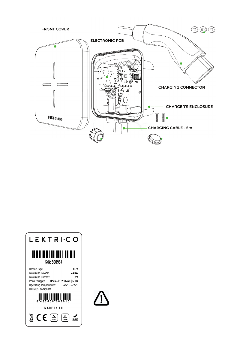
2. MEET YOUR 1P7K CHARGER............................................................................................... 6
3. TECHNICAL DATA................................................................................................................. 8
3.1. General characteristics ............................................................................................... 8
3.2. Electrical characteristics............................................................................................ 8
3.3. Connectivity................................................................................................................. 8
3.4. Mechanical characteristics........................................................................................ 8
3.5. Environmental characteristics ................................................................................... 9
3.6. LED status.................................................................................................................... 9
3.7. Transport and storage .............................................................................................. 11
3.8. Applicable standards and certifications.................................................................. 11
4. 1P7K INSTALLATION............................................................................................................13
4.1. Necessary tools ..........................................................................................................13
4.2. Plan the installation ...................................................................................................13
4.3. Before installing 1P7K ................................................................................................14
4.4. Installation steps........................................................................................................15
4.5. Overall and mounting dimensions...........................................................................22
4.6. Troubleshooting ........................................................................................................23
5. OPERATING THE 1P7K CHARGER..................................................................................... 27
5.1. Before first use........................................................................................................... 26
5.2. Start the charging..................................................................................................... 26
5.3. Stop the charging......................................................................................................26
5.4. Emergency stop ........................................................................................................26
5.5. Health and Safety ..................................................................................................... 27
6. 1P7K CHARGER CONFIGURATION....................................................................................28
7. Load balancing sensor installation and configuration ...................................................29
8. Configure with LEKTRICO APP..........................................................................................34
9. MAINTENANCE AND SUPPORT........................................................................................36
9.1. Maintenance ...............................................................................................................36
9.2. Support ......................................................................................................................36
9.3. Warranty..................................................................................................................... 37
10. NOTES ................................................................................................................................40

1P7K user and installation manual 5
1. SAFETY INSTRUCTIONS
ELECTRICAL WARNINGS
Before starting to install and operate the 1P7K charger,
the user must always read this document very carefully,
take into consideration all the warnings and follow all the
instructions as described in this manual.
Failure to do so may result in electric shock which can be
fatal or cause serious physical injuries.
DO NOT open the front cover when the 1P7K charger is
functioning, electric shock hazard.
DO NOT touch the connector’s pins.
DO NOT insert any tools inside the type 2 vehicle
connector.
DO NOT touch any pins, electronic components and
product.
Never install a product that is damaged.
Failure to do so may result in electric shock and/or
material damages (electric vehicle included).
1P7K charger must always be installed by qualified personnel and in
accordance with the electrical regulations applicable in your country.
1P7K charger is an electrical device that is always connected to 230VAC
therefore touching uninsulated parts (e.g. interior PCB pins, connectors,
uninsulated parts of the wires) will result in an electric shock.
If opening the front cover is necessary (e.g. during installation), always cut off
the power supply of the charger from the dedicated circuit breaker.
The 1P7K charger must be operated only by adults.
Adaptors, conversion adapters and cord extension sets are not allowed to be
used!
Stop the supply in case the Red LED appears!
CAUTION
CAUTION
ESD CAUTION
CAUTION

1P7K user and installation manual6
1P7K is a compact connected and simple to use charger.
Congratulations on joining the electro-revolution!
Your new 1P7K device is a single-phase charger with the capacity of charging
your EV with up to 7,4 kW power. Its smart features allow you to remotely
control and configure the charger using the LEKTRI.CO mobile application.
To get started, after the installation, download the application and follow the
instructions to connect it to your Wi-Fi network.
FEATURES
• Easy installation
• Compatible with any EV
• 5-meter charging cable with Type 2 connector
• Extend your 1P7K charger with our M2W module for smart load and
charge balancing. Your 1P7K charger is smart-home ready and can be
integrated into your smart home ecosystem.
• Remote charge Start and Stop
• Load balancing: automated dynamic charge adjustment to avoid circuit
breaker overload with EM add-on
• PV charge: charge your EV with green energy with EM add-on
• Schedule charging
• Check our webpage for more information and systems supported.
SAFETY FEATURES
•
and 30mA AC
• Overcurrent protection
• Overtemperature protection
Add your 1P7K charger to the LEKTRI.CO network to publicly share or earn
money by selling charging sessions. Contact us for more information (see 8.2
Support).
2. MEET YOUR 1P7K CHARGER

1P7K user and installation manual 7
The product label can be found on the backside of the charger. The label
provides useful information about the product:
• Manufacturer
• Serial number and a barcode
• Electrical characteristics
• Environmental characteristics
• Certifications
Fig. 1 Main components of the 1P7K charger
Fig. 2 The product label of the 1P7K charger
RUBBER SEAL
CABLE GLAND CAP
SCREWS
Extra label should be kept somewhere
safe such as on the inside of the breaker
board door. The information on the
label can be helpful for debugging and
support.
ATTENTION

1P7K user and installation manual8
3. DATASHEET
3.1. GENERAL CHARACTERISTICS
• Charging mode: Mode 3
• Connector: IEC 62196 Type 2
3.2. ELECTRICAL CHARACTERISTICS
• Nominal voltage: 230VAC
• Nominal frequency: 50Hz
• Charging current: maximum 32A
• Programmable charging current: 6A ... 32A
• Charging power: 1.4kW ... 7.4kW
• Standby power consumption: 3.5W
• 22;
• Power inputs: L, N, PE
3.3. CONNECTIVITY
•
3.4. MECHANICAL CHARACTERISTICS
• Overall dimensions: 190mm x 190mm x 88mm
• Weight: 4kg (including the charging cable, connector and packaging).
• Protection class: IP54
• Shock protection: IK10
•
• Power supply cable connectors: WAGO™ lever-action connector, mounted
on PCB.
• Charging cable length: 5m

1P7K user and installation manual 9
• Mounting solutions:
on a wall;
on a metal pillar (optional - can be purchased separately);
3.5. ENVIRONMENTAL CHARACTERISTICS
•
•
• Relative humidity: maximum 96%, non-condensing
3.6. LED STATUS
1P7K charger has one status LED on the front cover shaped like a cross which
lights in different colours depending on the charger’s status.

1P7K user and installation manual10
GREEN fading in and out: available and connected to Wi-Fi.
GREEN continuously lit: available and unused (not
connected to the electric vehicle).
continuously lit: connected to the electric vehicle and
waiting for the car to start the charging process.
PURPLE continuously lit: connected to the electric vehicle
and waiting for the remote server to authorize the start of
the charging process.
WHITE, each segment is lit in a clockwise rotating
pattern: connected to the electric vehicle and charging.
WHITE, a single segment is pulsating: Charging is paused.
The charging process may pause, if not enough power is
available, according to the set load balancing mode.
WHITE - static - charging in precise PWM Mode.
RED continuously lit: error - general fault, charging
not possible please see the Troubleshooting
section or contact the manufacturer (for
contact details see 8.2 Support section).
RED fading in and out: charger is locked and cannot be
used. This mode is useful for maintenance or testing
purposes
YELLOW continuously lit: the charger is performing a
firmware update.
1P7K CHARGER’S LED
Different charger statuses are represented by different LED colours as
described below:

1P7K user and installation manual 11
3.7. TRANSPORT AND STORAGE
The 1P7K charger must be transported with great care to avoid any impact
forces that might damage the product.
CAUTION
Do not put heavy loads on top of the charger’s package.
Do not step on the charger, charging cable or
connector.
The 1P7K charger must be stored in his package in a dust-free environment
than 96% non-condensing.
3.8.
To ensure a high-quality product, 1P7K was designed and manufactured in
accordance with the next standards:
•
requirements.
•
electric vehicle charging station.
• IEC 60068 Environmental testing.
•
• Directive 2014/30/EU regarding electromagnetic compatibility.
• BS EN 55032 Electromagnetic compatibility of multimedia equipment.
Emission Requirements.
•
and measurement techniques. Electrostatic discharge immunity test.
•
and measurement techniques. Electrical fast transient/burst immunity
test.
•
and measurement techniques. Surge immunity test.

1P7K user and installation manual12
In addition to the above standards the 1P7K charger has the next certifications:
• CE certification – compliance with the health, safety and
environmental protection standards for the European
• Restriction of hazardous substances – the design and the
manufacturing process of this product is compliant with the
RoHS 2 directive as per 2011/65/EU.
• Waste certifications – compliance with WEEE Directive
2012/19/EC
(waste electrical and electronic equipment directive).
This product must never be disposed of together with
household waste.

1P7K user and installation manual 13
4.1. NECESSARY TOOLS
To properly install the 1P7K charger, the following tools are required:
Hammer Drill machine Drill bits Step drill bit Screwdrivers
Measuring
tape
Marker/pencil Cable
cutting plier
Cable
stripping
plier
Utility knife
4.2. PLAN THE INSTALLATION
Before starting the installation, the following recommendations must be taken
into consideration:
• make sure the charger can be installed vertically, on a sturdy and fire-
resistant wall or on the optional metal pillar that can be purchased
separately;
• make sure there is enough space to install the charger (see chapter 4.5
Overall and mounting dimensions and Fig. 14 Free area around the 1P7K
charger when installed on a wall);
• make sure that the IP54 protection class of the charger can be maintained
(protected against dust and water splashes).
4. 1P7K INSTALLATION
the user must always read this document very carefully,
take into consideration all the warnings and follow all the
instructions as described in this manual.
CAUTION

1P7K user and installation manual14
• make sure that the necessary power supply cable (not included) from
the junction box to the charger can be installed in accordance with the
electrical regulations applicable in your country;
• make sure that the electric vehicle can be parked for a long period in the
vicinity of the charger in such a way that the included charging connector
with its 5m of cable can be plugged into the electric vehicle’s charging
port;
• if an optional metal pillar is used, make sure that this is mounted in the
highest point of the floor, in such a way that during rain the metal pillar
base will not be sitting in a puddle of water.
4.3.
Before installing the 1P7K charger, the electrical installation for the power
supply of the charger must be put in place. The electrical installation for the
power supply of the charger must have the next characteristics:
• single-phase, 3-wires: L, N and PE;
• maximum power supported: 7,4kW;
• an appropriated electrical protection in the junction box; The electrical
protection of the 1P7K charger must contain a residual current device
breaking capacity of 6kA.
NOTE
Check local electrical regulations regarding the
necessity of installing an external emergency switch for
the 1P7K charger.
• a 3-wire flexible, flame-retardant and self-extinguishing cable with a wire
cross-section of 6mm2 or 10mm2;
• the cable must be properly secured and protected.

1P7K user and installation manual 15
CAUTION
Due to the danger of electric shock, the electrical installation
for the power supply of the charger must be always carried out
by qualified personnel and in accordance with the electrical
regulations applicable in your country.
Failure to do so may result in electric shock which can be fatal
or cause serious physical injuries.
NOTE
to user, the required electrical equipment (e.g. breaker, wiring,
installation accessories) is not unique and therefore is not
delivered with the 1P7K charger.
4.4. INSTALLATION STEPS
Depending on where the 1P7K charger will be placed, there are two methods to
install the charger:
1. Installation on a wall.
2. Installation on a metal pillar.
When deciding which installation method is best suited for you consider the
recommendations described in section 4.2 Plan the installation.
4.4.1. INSTALLATION ON A WALL
To install the 1P7K charger on a wall follow the installation steps described
below.
Installation steps:
1. Remove the charger from its packaging and make sure that all the
components are included:
• the front cover of the charger;
• • the main body of the charger (electronic PCB installed in the
plastic enclosure);
•
connected to the electronic PCB;
• Quick installation guide with integrated drill template;
For more details see Fig. 1 Main components of the 1P7K charger.

1P7K user and installation manual16
2. Inspect the charger for any damages. The main components of the 1P7K
charger described in step 1, must not reveal any cracks, defects or other
imperfections. Also, the electrical insulation of the included charging
cable must be intact. If defects are found, do not proceed with the
installation process and immediately contact the manufacturer or the local
supplier. For contact details please see section 8.2 Support.
CAUTION
Never install a product that is damaged.
Failure to do so may result in electric shock and/or
material damages (electric vehicle included).
3. Determine the best place for the charger to be installed, taking into
consideration the recommendations described in section 4.2 Plan the
installation.
4. Mark on the wall the position of the charger’s 3 mounting points. For a
quick and correct marking of the mounting points please use the provided
drilling template. It is recommended to install the 1P7K charger at 1,3m
above the floor.
5. Drill holes in the wall where the
mounting points are marked. The
diameter of the holes depends
on what type of screw anchor
are used. Always use anchor
screws dedicated to your wall
surface (e.g. brick/concrete,
drywall, polystyrene insulation)
and follow the recommendations
of the anchor screw
manufacturer. Anchor screws and
corresponding screws are not
included.
6. Insert the screw anchor into the
holes and make sure they are
inserted all the way. If necessary,
use a hammer and gently tap the
anchor screws all the way into
the holes.
7. Using a step drill bit, drill a 30mm
diameter hole into one of the
existing precut areas from the Fig. 4 Drilling template for the 1P7K charger’s
mounting points

1P7K user and installation manual 17
plastic enclosure. These easy to cut areas are used to insert the power
supply cable into the main body of the charger.
There are 2 available easy to cut areas through which the power supply
cable can be inserted into the charger. One area is on the rear of the
enclosure and one area is on the bottom left side.
8. If the rear cut-out area is used, insert the provided sealing cap in the cut-
out hole. Insert the power supply cable through the sealing cap, to ensure
water tightness. If the bottom left cut-out hole is used skip this step.
9. Fix the main body of the charger on the wall by inserting the screws with
the provided rubber sealing washer through the mounting points and
tighten them with a screwdriver by hand.
Fig. 5 Cut out areas for the power supply cable

1P7K user and installation manual18
CAUTION
Overtightening the screws may cause the plastic
enclosure of the charger to break.
10. Install the cable gland in the bottom left cut-out area created at step 7. Fix
the cable gland into position by tightening the lock nut.
11. Strip the main insulation of the power supply cable in such a way that 2
cm of insulation will be left inside the plastic enclosure of the charger.
12. Measure and cut the 3-wires of the power supply cable, in such a way
that they can be easily and fully inserted into the cable connectors
mounted on PCB.
13. Strip 12mm of insulation for each of the 3-wires of the power supply
14. Insert the power supply cable through the bottom cable gland. To
gland must be used.
15. Open the levers of the WAGO™ connectors that are mounted on the left
side of the PCB.
Fig. 6 Mounting points of the 1P7K
Charger
Sealing
Wall

1P7K user and installation manual 19
16. Insert the 3-wires of the power supply cable into the WAGO™ connectors
mounted on PCB and close each lever of the connectors. Be sure that
the wires are fully inserted into the connectors, no stripped parts of the
wires or strand wires must be visible (electrical protection against direct
contact). Incorrect connection can result in improper contact which may
cause a fire hazard.
CAUTION
Always follow the wires succession as labelled on
succession may lead to an electric shock which can be
fatal or cause serious physical injuries or fire.
17. Tighten the sealing nut of the cable gland, making sure that the cable
gland seal is properly fit.
18. Verify that the rubber seal mounted on the inside border of the enclosure
is fitted tight in the designated place. If the front cover is installed over
a rubber seal that is fitted improperly the IP54 protection class of the
charger may be affected.
19. Install the front cover by gently pushing it into place, first in the bottom 2
fixing hooks and then in the 2 top fixing hooks.
Fig. 7 Stripping insulation length for each of the 3-wires of the
power supply cable
Fig. 8 Wires succession of the power supply cable

1P7K user and installation manual20
20. Secure the front cover by tightening the 2 screws from the lower part. A
Philips screwdriver is needed with a PH1 head.
21. Power up the 1P7K charger by arming the dedicated circuit breaker.
22. Check the front cover LED status. For more details about the front cover
LED see 3.6 LED status.
23. Connect your 1P7K charger to your Wi-Fi network to manage and
configure it. To do this please follow the instructions on chapter 7.
Configure with LEKTRICO App.
Fig. 9 Rubber seal
Fig. 10 Install the front cover
Fig. 11 Front cover securing screws
Other manuals for 1P7K
1
Table of contents
Other Lektri-Co Batteries Charger manuals