SICK GRSE18 User manual

GRSE18
Operating Instruction
DE/EN/FR/PT/IT/ES/ZH/JA/RU
8016954.16B5
OPERATING INSTRUCTION

Described product
GR18
GRSE18
Manufacturer
SICK AG
Erwin-Sick-Str. 1
79183 Waldkirch
Germany
Production location
Legal information
This work is protected by copyright. Any rights derived from the copyright shall be
reserved for SICK AG. Reproduction of this document or parts of this document is only
permissible within the limits of the legal determination of Copyright Law. Any modifica‐
tion, abridgment or translation of this document is prohibited without the express writ‐
ten permission of SICK AG.
The trademarks stated in this document are the property of their respective owner.
© SICK AG. All rights reserved.
Original document
This document is an original document of SICK AG.
2006/42/EC
NO
SAFETY
8016953.16B5 | SICK
Subject to change without notice 1

Through-beam photoelectric sensor
Operating instructions
2 Safety notes
■Read the operating instructions before commissioning.
■Connection, mounting, and setting may only be performed by trained specialists.
■Not a safety component in accordance with the EU Machinery Directive. Only for use in appli‐
cations in accordance with NFPA 79. UL-listed adapters with connecting cables are available.
Enclosure type 1
■When commissioning, protect the device from moisture and contamination.
■These operating instructions contain information required during the life cycle of the sensor.
3 Correct use
The GRSE18 is an opto-electronic through-beam photoelectric sensor (referred to as "sensor" in
the following) for the optical, non-contact detection of objects, animals, and persons. A sender
(WS) and a receiver (WE) are required for operation. If the product is used for any other purpose
or modified in any way, any warranty claim against SICK AG shall become void.
Image 1: GRSE18-xxxx2
Image 2: GRSE18-xxxx7
Irrtuemer | SICK 1
8016954.16B5

4 Commissioning
1 Observe the application conditions: Adjust the distance between the sender and the receiver
according to the corresponding diagram (x = sensing range, y = operating reserve).
If several through-beam photoelectric sensors which are installed next to one another are to
be used, we recommend swapping the sender/receiver arrangement at every second
through-beam photoelectric sensor and ensuring that there is sufficient distance between
the through-beam photoelectric sensors. By doing this, mutual interference can be preven‐
ted.
Image 3: H
2 Mount sensors (sender and receiver) using suitable mounting brackets (see the SICK range
of accessories). Align the sender and receiver with each other [K].
Observe the maximum permissible tightening torque of the sensor of 2.0 Nm for metal/0.9
Nm for plastic [K].
Image: K: GRSE18-x24x7
Commissioning
2| SICK Irrtuemer
8016954.16B5

Image: K: GRSE18-x24x2
3 The sensors must be connected in a voltage-free state (VS = 0 V). The information in the gra‐
phics [B] must be observed, depending on the type of connection:
– Male connector connection: pin assignment
– Cable: core color
Image: B: GRSE18-x11xx
Only apply voltage/switch on the power supply (VS > 0 V) once all electrical connections have
been completed. The green LED indicator lights up on the sensor.
Explanations of the connection diagram (Graphic B):
Switching outputs Q and /Q (according to Graphic B):
GRSE18-P (PNP: load -> M)
GRSE18-N (NPN: load -> L+)
TI = test input (see Additional functions)
4 Align the sender with the receiver. Select the position so that the red emitted light beam hits
the receiver. Tip: Use white paper or a reflector as an alignment aid. No light spot is visible
with infrared devices. The correct alignment can only be detected via the LED indicators.
Please refer to Graphics C and E in relation to this. The sender must have a clear view of the
receiver, and no object may be in the optical path. You must ensure that the optical open‐
ings (front screen) of the sensors are completely clear.
Image 4: E
Commissioning
Irrtuemer | SICK 3
8016954.16B5

5
Sensor with potentiometer:
The sensitivity is adjusted with the potentiometer (type: 270°). Clockwise rotation: operating
reserve increased; counterclockwise rotation: operating reserve reduced. We recommend
setting the potentiometer to "Maximum."
The sensor is adjusted and ready for operation. Refer to Graphics C and G to check the func‐
tion. If the switching output fails to behave in accordance with Graphic C, check application
conditions. See section Fault diagnosis.
Image 5: C
Image 6: G
4| SICK Irrtuemer
8016954.16B5

6 Additional functions
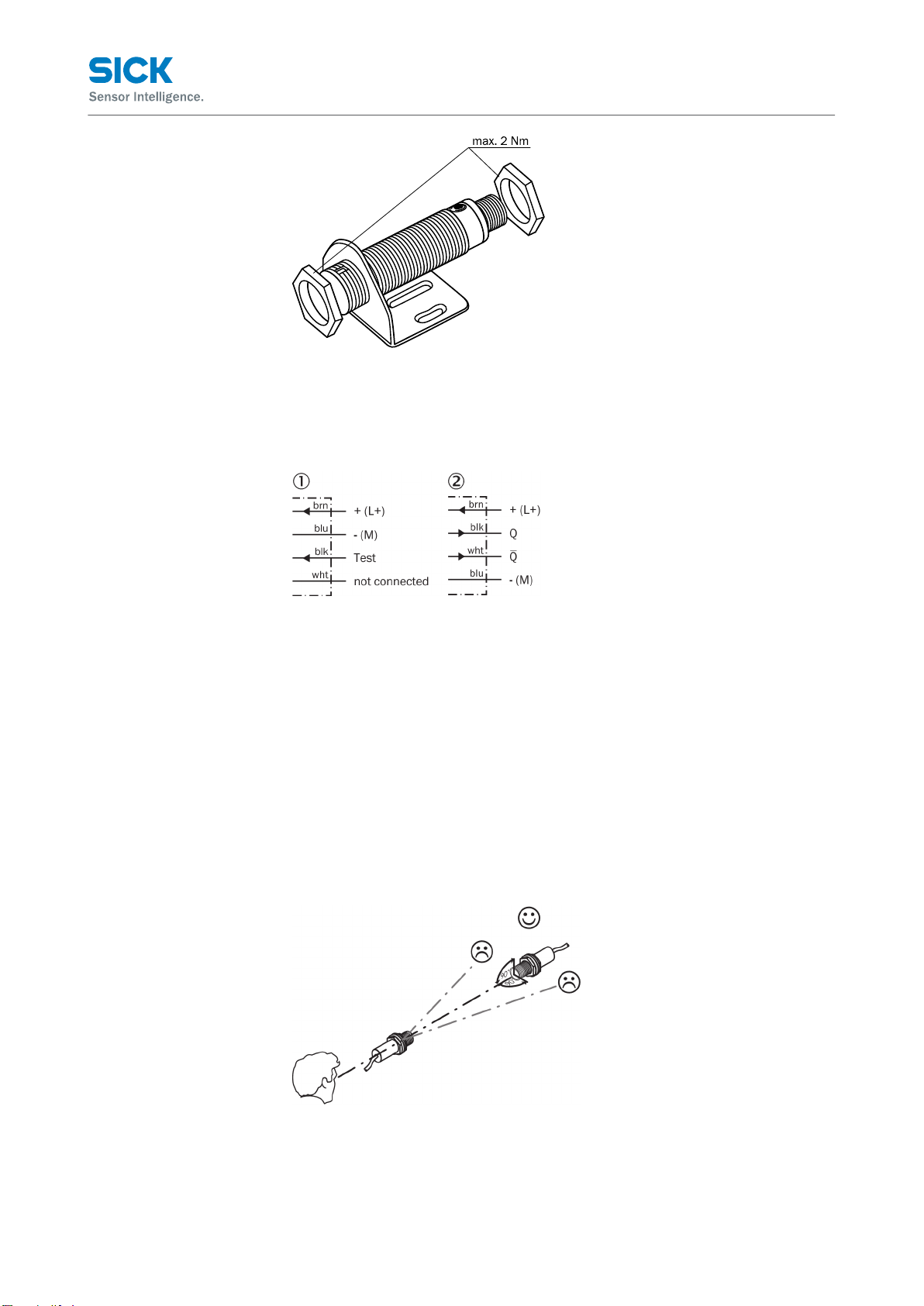
The GRSE18 sensor features a test input ("TI" on the connection diagram [B]), which can be used
to check that the sensor is functioning correctly: If cable sockets with LED indicators are used,
you must ensure that the TI is assigned accordingly.
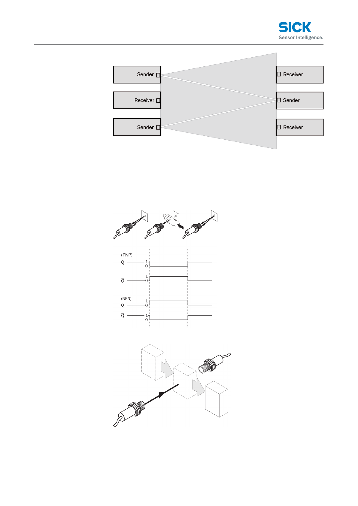
There must be no object between the sender and receiver; activate the test input (see the con‐
nection diagram [B], TI at 0 V). The send LED is shut down or the detection of an object is simula‐
ted. Refer to Graphics C and G to check the function. If the switching output fails to behave in
accordance with Graphic C, check application conditions. See section Fault diagnosis.
7 Fault diagnosis
Table 8 indicates which measures are to be taken if the sensor stops working.
8 Tab_Fault diagnosis
LED indicator/fault pattern /
LED indicator/fault pattern
Cause /
Cause
Measures /
Measures
Green LED does not light up /
Green LED does not light up
No voltage or voltage below the
limit values /
No voltage or voltage below the
limit values
Check the power supply, check all
electrical connections (cables and
plug connections) /
Check the power supply, check all
electrical connections (cables and
plug connections)
Green LED does not light up /
Green LED does not light up
Voltage interruptions /
Voltage interruptions
Ensure there is a stable power
supply without interruptions /
Ensure there is a stable power
supply without interruptions
Green LED does not light up /
Green LED does not light up
Sensor is faulty /
Sensor is faulty
If the power supply is OK, replace
the sensor /
If the power supply is OK, replace
the sensor
Green LED lights up, no output sig‐
nal when object is detected /
Green LED lights up, no output sig‐
nal when object is detected
Test input (TI) is not connected
properly /
Test input (TI) is not connected
properly
See the note on connecting the
TI /
See the note on connecting the TI
Yellow LED flashes /
Yellow LED flashes
Sensor is still ready for operation,
but the operating conditions are
not ideal /
Sensor is still ready for operation,
but the operating conditions are
not ideal
Check the operating conditions:
Fully align the beam of light (light
spot) with the receiver. / Clean the
optical surfaces / Readjust the
sensitivity (potentiometer) / If the
potentiometer is set to the max.
sensing range: Reduce the dis‐
tance between the sender and the
receiver, and check against Gra‐
phic E / Check sensing range and
adjust if necessary, see Graphic
E /
Check the operating conditions:
Fully align the beam of light (light
spot) with the receiver. / Clean
the optical surfaces / Readjust
the sensitivity (potentiometer) / If
the potentiometer is set to the
max. sensing range: Reduce the
distance between the sender and
the receiver, and check against
Graphic E / Check sensing range
and adjust if necessary, see Gra‐
phic E
Additional functions
Irrtuemer | SICK 5
8016954.16B5

LED indicator/fault pattern /
LED indicator/fault pattern
Cause /
Cause
Measures /
Measures
Yellow LED lights up, no object in
the path of the beam /
Yellow LED lights up, no object in
the path of the beam
The beam of light of a photoelect‐
ric through-beam sensor hits the
receiver of another (neighbo‐
ring) photoelectric through-beam
sensor /
The beam of light of a photoelect‐
ric through-beam sensor hits the
receiver of another (neighbo‐
ring) photoelectric through-beam
sensor
Swap the sender and receiver
arrangement at every second pho‐
toelectric through-beam sensor
and ensure that there is sufficient
distance between the through-
beam photoelectric sensors /
Swap the sender and receiver
arrangement at every
second photoelectric through-
beam sensor and ensure that
there is sufficient distance bet‐
ween the through-beam photo‐
electric sensors
9 Disassembly and disposal
The sensor must be disposed of according to the applicable country-specific regulations. Efforts
should be made during the disposal process to recycle the constituent materials (particularly pre‐
cious metals).
10 Maintenance
SICK sensors are maintenance-free.
We recommend doing the following regularly:
1. Clean the external lens surfaces
2. Check the screw connections and plug-in connections
No modifications may be made to devices.
Subject to change without notice. Specified product properties and technical data are not written
guarantees.
Einweg-Lichtschranke
Betriebsanleitung
13 Sicherheitshinweise
■Vor der Inbetriebnahme die Betriebsanleitung lesen.
■Anschluss, Montage und Einstellung nur durch Fachpersonal.
■Kein Sicherheitsbauteil gemäß EU-Maschinenrichtlinie. Nur zur Verwendung in Anwendungen
gemäß NFPA 79. Von UL gelistete Adapter mit Anschlusskabeln sind verfügbar. Enclosure
type 1
■Gerät bei Inbetriebnahme vor Feuchte und Verunreinigung schützen.
■Diese Betriebsanleitung enthält Informationen, die während des Lebenszyklus des Sensors
notwendig sind.
14 Bestimmungsgemäße Verwendung
Disassembly and disposal
6| SICK Irrtuemer
8016954.16B5

Die GRSE18 ist eine optoelektronische Einweg-Lichtschranke (im Folgenden Sensor genannt) und
wird zum optischen, berührungslosen Erfassen von Sachen, Tieren und Personen eingesetzt.
Zum Betrieb ist ein Sender (WS) und ein Empfänger (WE) erforderlich. Bei jeder anderen Verwen‐
dung und bei Veränderungen am Produkt verfällt jeglicher Gewährleistungsanspruch gegenüber
der SICK AG.
Abb. 7: GRSE18-xxxx2
Abb. 8: GRSE18-xxxx7
15 Inbetriebnahme
1 Einsatzbedingungen beachten: Distanz zwischen Sender und Empfänger mit dem zugehöri‐
gen Diagramm [vgl. H] abgleichen (x = Schaltabstand, y = Funktionsreserve).
Beim Einsatz von mehreren Einweg-Lichtschranken, die nebeneinander installiert werden,
empfehlen wir, bei jeder zweiten Einweg-Lichtschranke die Anordnung von Sender und Emp‐
fänger zu tauschen, bzw. genügend Abstand zwischen den Einweg-Lichtschranken einzuhal‐
ten. Damit können gegenseitige Beeinflussungen vermieden werden [vgl. I].
Bestimmungsgemäße Verwendung
Irrtuemer | SICK 7
8016954.16B5

Abb. 9: H
2 Sensoren (Sender und Empfänger) an geeignete Befestigungswinkel montieren (siehe SICK-
Zubehör-Programm). Sender und Empfänger zueinander ausrichten [vgl. K].
Maximal zulässiges Anzugsdrehmoment des Sensors von 2,0 Nm für Metall / 0,9 Nm für
Kunststoff beachten [vgl. K].
Abb.: K: GRSE18-x24x7
Abb.: K: GRSE18-x24x2
3 Anschluss der Sensoren muss spannungsfrei (VS = 0 V) erfolgen. Je nach Anschlussart sind
die Informationen in den Grafiken [vgl. B] zu beachten:
– Steckeranschluss: Pinbelegung
– Leitung: Adernfarbe
Inbetriebnahme
8| SICK Irrtuemer
8016954.16B5

Abb.: B: GRSE18-x24xx
Abb.: B: GRSE18-x11xx
Erst nach Anschluss aller elektrischen Verbindungen die Spannungsversorgung (VS > 0 V)
anlegen bzw. einschalten. Am Sensor leuchtet die grüne Anzeige-LED.
Erläuterungen zum Anschlussschema (Grafik B):
Schaltausgänge Q bzw. /Q (gemäß Grafik B):
GRSE18-P (PNP: Last -> M)
GRSE18-N (NPN: Last -> L+)
TE = Testeingang (siehe Zusatzfunktionen)
4 Sender auf Empfänger ausrichten. Positionierung so wählen, dass der rote Sendelichtstrahl
auf den Empfänger auftrifft. Tipp: weißes Papier oder Reflektor als Ausrichthilfe verwenden.
Bei Infrarotgeräten ist kein Lichtfleck sichtbar. Die korrekte Ausrichtung kann nur über die
Anzeige-LEDs erkannt werden. Siehe dazu Grafiken C und E. Der Sender muss freie Sicht
auf den Empfänger haben, es darf sich kein Objekt im Strahlengang befinden. Es ist darauf
zu achten, dass die optischen Öffnungen (Frontscheiben) der Sensoren vollständig frei sind.
Abb. 10: E
Inbetriebnahme
Irrtuemer | SICK 9
8016954.16B5

5
Sensor mit Potentiometer:
Mit dem Potentiometer (Art: 270°) wird die Empfindlichkeit eingestellt. Drehung nach
rechts: Erhöhung der Funktionsreserve, Drehung nach links: Verringerung der Funktionsre‐
serve. Wir empfehlen, das Potentiometer auf "Maximal" zu stellen.
Sensor ist eingestellt und betriebsbereit. Zur Überprüfung der Funktion Grafik C und G
heranziehen. Verhält sich der Schaltausgang nicht gemäß Grafik C, Einsatzbedingungen prü‐
fen. Siehe Abschnitt Fehlerdiagnose.
Abb. 11: C
Abb. 12: G
10 | SICK Irrtuemer
8016954.16B5

17 Zusatzfunktionen
Der Sensor GRSE18 verfügt über einen Testeingang („TE“ im Anschlussschema [B]), mit dem die
ordnungsgemäße Funktion des Sensors überprüft werden kann: bei Verwendung von Leitungsdo‐
sen mit LED-Anzeigen ist darauf zu achten, dass der TE entsprechend belegt ist.
Es darf sich kein Objekt zwischen Sender und Empfänger befinden, Testeingang aktivieren (siehe
Anschlussschema [B], TE nach 0 V). Sende-LED wird abgeschaltet, bzw. es wird simuliert, dass
ein Objekt erkannt wird. Zur Überprüfung der Funktion Grafik C und G heranziehen. Verhält sich
der Schaltausgang nicht gemäß Grafik C, Einsatzbedingungen prüfen. Siehe Abschnitt Fehlerdi‐
agnose.
18 Fehlerdiagnose
Tabelle 19 zeigt, welche Maßnahmen durchzuführen sind, wenn die Funktion des Sensors nicht
mehr gegeben ist.
19 Tab_Fehlerdiagnose
Anzeige-LED / Fehlerbild /
LED indicator/fault pattern
Ursache /
Cause
Maßnahme /
Measures
grüne LED leuchtet nicht /
Green LED does not light up
keine Spannung oder Spannung
unterhalb der Grenzwerte /
No voltage or voltage below the
limit values
Spannungsversorgung prüfen,
den gesamten elektrischen
Anschluss prüfen (Leitungen und
Steckerverbindungen) /
Check the power supply, check all
electrical connections (cables and
plug connections)
grüne LED leuchtet nicht /
Green LED does not light up
Spannungsunterbrechungen /
Voltage interruptions
Sicherstellen einer stabilen Span‐
nungsversorgung ohne Unterbre‐
chungen /
Ensure there is a stable power
supply without interruptions
grüne LED leuchtet nicht /
Green LED does not light up
Sensor ist defekt /
Sensor is faulty
Wenn Spannungsversorgung in
Ordnung ist, dann Sensor austau‐
schen /
If the power supply is OK, replace
the sensor
grüne LED leuchtet, kein Ausgangs‐
signal bei Objektdetektion /
Green LED lights up, no output sig‐
nal when object is detected
Testeingang (TE) ist nicht korrekt
angeschlossen /
Test input (TI) is not connected
properly
Siehe Hinweis für Anschluss des
TE /
See the note on connecting the TI
Zusatzfunktionen
Irrtuemer | SICK 11
8016954.16B5

Anzeige-LED / Fehlerbild /
LED indicator/fault pattern
Ursache /
Cause
Maßnahme /
Measures
gelbe LED blinkt /
Yellow LED flashes
Sensor ist noch betriebsbereit,
aber die Betriebsbedingungen
sind nicht optimal /
Sensor is still ready for operation,
but the operating conditions are
not ideal
Betriebsbedingungen prüfen:
Lichtstrahl (Lichtfleck) vollständig
auf den Empfänger ausrichten /
Reinigung der optischen Flächen /
Empfindlichkeit (Potentiometer)
neu einstellen / falls Potentiome‐
ter auf max. Schaltabstand einge‐
stellt: Abstand zwischen Sender
und Empfänger verringern und mit
Grafik E überprüfen / Schaltab‐
stand überprüfen und ggfs.
anpassen, siehe Grafik E /
Check the operating conditions:
Fully align the beam of light (light
spot) with the receiver. / Clean
the optical surfaces / Readjust
the sensitivity (potentiometer) / If
the potentiometer is set to the
max. sensing range: Reduce the
distance between the sender and
the receiver, and check against
Graphic E / Check sensing range
and adjust if necessary, see Gra‐
phic E
gelbe LED leuchtet, kein Objekt im
Strahlengang /
Yellow LED lights up, no object in
the path of the beam
Der Lichtstrahl einer Einweg-Licht‐
schranke trifft auf den Empfänger
einer anderen (benachbarten)
Einweg-Lichtschranke /
The beam of light of a photoelect‐
ric through-beam sensor hits the
receiver of another (neighbo‐
ring) photoelectric through-beam
sensor
Bei jeder zweiten Einweg-Licht‐
schranke die Anordnung von Sen‐
der und Empfänger tauschen,
bzw. genügend Abstand zwischen
den Einweg-Lichtschranken ein‐
halten. /
Swap the sender and receiver
arrangement at every
second photoelectric through-
beam sensor and ensure that
there is sufficient distance bet‐
ween the through-beam photo‐
electric sensors
20 Demontage und Entsorgung
Die Entsorgung des Sensors hat gemäß den länderspezifisch anwendbaren Vorschriften zu erfol‐
gen. Für die enthaltenen Wertstoffe (insbesondere Edelmetalle) ist im Rahmen der Entsorgung
eine Verwertung anzustreben.
21 Wartung
SICK-Sensoren sind wartungsfrei.
Wir empfehlen, in regelmäßigen Abständen
1. die optischen Grenzflächen zu reinigen
2. Verschraubungen und Steckverbindungen zu überprüfen
Veränderungen an Geräten dürfen nicht vorgenommen werden.
Irrtümer und Änderungen vorbehalten. Angegebene Produkteigenschaften und technische Daten
stellen keine Garantieerklärung dar.
Barrière émetteur-récepteur
Demontage und Entsorgung
12 | SICK Irrtuemer
8016954.16B5

Notice d'instruction
24 Consignes de sécurité
■Lire la notice d'instruction avant la mise en service.
■Confier le raccordement, le montage et le réglage uniquement à un personnel spécialisé.
■Il ne s'agit pas d'un composant de sécurité au sens de la directive machines CE. Utilisation
uniquement pour des applications selon la NFPA 79 Des adaptateurs listés UL avec câbles
de connexion sont disponibles. Enclosure type 1
■Protéger l'appareil contre l'humidité et les impuretés lors de la mise en service.
■Cette notice d'instruction contient des informations nécessaires pendant toute la durée de
vie du capteur.
25 Utilisation conforme
GRSE18 est une barrière émetteur-récepteur optoélectronique (appelée capteur dans ce docu‐
ment) qui permet la détection optique sans contact d'objets, d'animaux et de personnes. Un
émetteur (WS) et un récepteur (WE) sont nécessaires à son fonctionnement. Toute autre utilisa‐
tion ou modification du produit annule la garantie de SICK AG.
Image 13: GRSE18-xxxx2
Image 14: GRSE18-xxxx7
Consignes de sécurité
Irrtuemer | SICK 13
8016954.16B5

26 Mise en service
1 Respecter les conditions d'utilisation : comparer la distance entre l'émetteur et le récepteur
avec le diagramme correspondant [voir H] (x = portée, y = réserve de fonctionnement).
Si plusieurs barrières émetteur-récepteur sont installées les unes à côté des autres, nous
recommandons d'intervertir la place de l'émetteur et du récepteur une fois sur deux ou de
laisser suffisamment d'espace entre les barrières émetteur-récepteur. Ceci permet d'éviter
les interférences mutuelles [voir I].
Image 15: H
2 Monter les capteurs (émetteur et récepteur) sur des équerres de fixation adaptées (voir la
gamme d'accessoires SICK). Aligner l'émetteur sur le récepteur [voir K].
Respecter le couple de serrage maximal admissible du capteur de 2,0 Nm pour métal / 0,9
Nm pour plastique [voir K].
Image: K: GRSE18-x24x7
Mise en service
14 | SICK Irrtuemer
8016954.16B5

Image: K: GRSE18-x24x2
3 Le raccordement des capteurs doit s'effectuer hors tension (VS = 0 V). Selon le mode de rac‐
cordement, respecter les informations contenues dans les schémas [B] :
– Raccordement du connecteur : affectation des broches
– Câble : couleur des fils
Image: B: GRSE18-x24xx
Image: B: GRSE18-x11xx
Après avoir terminé tous les raccordements électriques, enclencher l'alimentation électrique
(VS > 0 V). La DEL verte s'allume sur le capteur.
Explications relatives au schéma de raccordement (schéma B) :
Sorties de commutation Q ou /Q (selon le schéma B) :
GRSE18-P (PNP : charge -> M)
GRSE18-N (NPN : charge -> L+)
TE = entrée test (voir fonctions supplémentaires)
4 Aligner l'émetteur sur le récepteur. Sélectionner la position de sorte que le faisceau lumi‐
neux émis rouge touche le récepteur. Conseil : utiliser un morceau de papier blanc ou le
réflecteur comme outil d'alignement. Aucun spot lumineux n'est visible pour les appareils
infrarouge. Seules les LED permettent de savoir si l'alignement est correct. Pour cela voir les
schémas C et E. L'émetteur doit disposer d'un champ de vision dégagé sur le récepteur, il ne
doit donc y avoir aucun objet dans la trajectoire du faisceau. S'assurer que les ouvertures
optiques (vitres frontales) des capteurs sont parfaitement dégagées.
Mise en service
Irrtuemer | SICK 15
8016954.16B5

Image 16: E
5
Capteur avec potentiomètre :
Le potentiomètre (réf. : 270°) permet de régler la sensibilité. Rotation vers la droite : aug‐
mentation de la réserve de fonctionnement, rotation vers la gauche : réduction de la réserve
de fonctionnement. Nous recommandons de régler le potentiomètre sur "Maximum".
Le capteur est réglé et prêt à être utilisé. Pour contrôler le fonctionnement, utiliser les sché‐
mas C et G. Si la sortie de commutation ne se comporte pas comme indiqué sur le schéma
C, vérifier les conditions d'utilisation. Voir la section consacrée au diagnostic.
Image 17: C
Mise en service
16 | SICK Irrtuemer
8016954.16B5

Image 18: G
28 Fonctions supplémentaires
Le capteur GRSE18 dispose d’une entrée test (« TE » dans le schéma de raccordement [B]) qui
permet de contrôler le bon fonctionnement du capteur : lorsque des connecteurs femelles équi‐
pés de DEL sont utilisés, s’assurer que l’entrée TE est correctement affectée.
Aucun objet ne doit se trouver entre l’émetteur et le récepteur ; activer l’entrée test (voir le
schéma de raccordement [B], TE sur 0 V). La LED d’émission est arrêtée ou une détection d’objet
est simulée. Pour contrôler le fonctionnement, utiliser les schémas C et G. Si la sortie de commu‐
tation ne se comporte pas comme indiqué sur le schéma C, vérifier les conditions d'utilisation.
Voir la section consacrée au diagnostic.
29 Diagnostic
Le tableau 30 présente les mesures à appliquer si le capteur ne fonctionne plus.
30 Tab_Diagnostic
LED d'état / image du défaut /
LED indicator/fault pattern
Cause /
Cause
/
Measures
La LED verte ne s'allume pas /
Green LED does not light up
Pas de tension ou tension infér‐
ieure aux valeurs limites /
No voltage or voltage below the
limit values
Contrôler l'alimentation électri‐
que, contrôler tous les branche‐
ments électriques (câbles et con‐
nexions) /
Check the power supply, check all
electrical connections (cables and
plug connections)
La LED verte ne s'allume pas /
Green LED does not light up
Coupures d'alimentation électri‐
que /
Voltage interruptions
S'assurer que l'alimentation élect‐
rique est stable et ininterrompue /
Ensure there is a stable power
supply without interruptions
La LED verte ne s'allume pas /
Green LED does not light up
Le capteur est défectueux /
Sensor is faulty
Si l'alimentation électrique est en
bon état, remplacer le capteur /
If the power supply is OK, replace
the sensor
La LED verte s'allume, pas de sig‐
nal de sortie en cas de détection
d'objet /
Green LED lights up, no output sig‐
nal when object is detected
L'entrée test (TE) n'est pas correc‐
tement raccordée /
Test input (TI) is not connected
properly
Voir les informations sur le raccor‐
dement de l'entrée test /
See the note on connecting the TI
Irrtuemer | SICK 17
8016954.16B5

LED d'état / image du défaut /
LED indicator/fault pattern
Cause /
Cause
/
Measures
La LED jaune clignote /
Yellow LED flashes
Le capteur est encore opération‐
nel, mais les conditions d'utilisa‐
tion ne sont pas idéales /
Sensor is still ready for operation,
but the operating conditions are
not ideal
Vérifier les conditions d'utilisa‐
tion : Diriger le faisceau lumineux
(spot lumineux) entièrement sur le
récepteur / Nettoyage des surfa‐
ces optiques / Régler à nouveau
la sensibilité (potentiomètre) / Si
le potentiomètre est réglé sur la
portée max. : réduire la distance
entre l'émetteur et le récepteur et
contrôler avec le schéma E / Con‐
trôler la portée et éventuellement
l'adapter, voir le schéma E /
Check the operating conditions:
Fully align the beam of light (light
spot) with the receiver. / Clean
the optical surfaces / Readjust
the sensitivity (potentiometer) / If
the potentiometer is set to the
max. sensing range: Reduce the
distance between the sender and
the receiver, and check against
Graphic E / Check sensing range
and adjust if necessary, see Gra‐
phic E
La LED jaune s'allume, pas d'objet
dans la trajectoire du faisceau /
Yellow LED lights up, no object in
the path of the beam
Le faisceau lumineux d'une barri‐
ère émetteur-récepteur atteint le
récepteur d'une autre barrière
émetteur-récepteur (voisine) /
The beam of light of a photoelect‐
ric through-beam sensor hits the
receiver of another (neighbo‐
ring) photoelectric through-beam
sensor
Pour une barrière émetteur-récep‐
teur sur deux, intervertir la place
de l'émetteur et du récepteur ou
laisser suffisamment d'espace
entre les barrières émetteur-
récepteur. /
Swap the sender and receiver
arrangement at every
second photoelectric through-
beam sensor and ensure that
there is sufficient distance bet‐
ween the through-beam photo‐
electric sensors
31 Démontage et mise au rebut
La mise au rebut du capteur doit respecter la réglementation nationale en vigueur. Dans le cadre
de la mise au rebut, veiller à recycler les matériaux (notamment les métaux précieux).
32 Maintenance
Les capteurs SICK ne nécessitent aucune maintenance.
Nous vous recommandons de procéder régulièrement
1. au nettoyage des surfaces optiques
2. au contrôle des vissages et des connexions enfichables
Ne procéder à aucune modification sur les appareils.
Sujet à modification sans préavis. Les caractéristiques du produit et techniques fournies ne sont
pas une déclaration de garantie.
Fotocélula unidirecional
Manual de instruções
Démontage et mise au rebut
18 | SICK Irrtuemer
8016954.16B5
Table of contents
Languages:
Other SICK Accessories manuals

SICK
SICK UM12 Series User manual

SICK
SICK LMS1104C-111031S01 User manual

SICK
SICK TiM361S User manual

SICK
SICK WL100-2 User manual

SICK
SICK MPB10 User manual

SICK
SICK WTB4FT DoubleLine User manual

SICK
SICK W24-2 User manual

SICK
SICK GTE6L-P1 Series User manual

SICK
SICK HTE18 Series User manual

SICK
SICK Bulkscan LMS511 User manual
Popular Accessories manuals by other brands

Galvin Engineering
Galvin Engineering CliniMix CMV2 Product installation guideline

Leviton
Leviton 31A00-8 installation instructions

FRENZEL
FRENZEL UFG0100BEU user manual

Hioki
Hioki Z2018 instruction manual

Johnson Hardware
Johnson Hardware 1601 SERIES instruction manual

Vega
Vega VEGAPULS 67 operating instructions