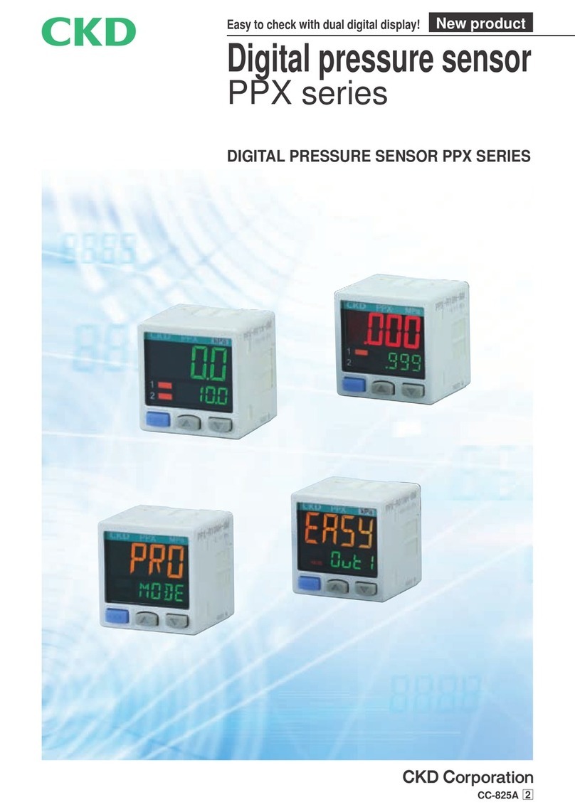
CKD PPX Series User manual

CC-825A 5
Digital pressure sensor
PPX Series
Visibility is improved with digital twin display! New product
DIGITAL PRESSURE SENSOR PPX SERIES

1

2

Positive pressure and vacuum conrmation or interlock
High function type
Manifold
Both vacuum pressure and burst pressure can be controlled with a single unit.
Contact conrmation
Digital pressure sensor applications
VRA2000
RP
PPX
PPX
PPX
PPX
Magnetic spring buffer
FBU2
PPX
PPX
PPX
Easy setting with auto reference/remote zero adjusting
Intro 1

MEMO
MEMO
Intro 2

JIS symbol
Digital pressure sensor
PPXSeries
Specifications
Descriptions Standard type High function type
For low pressure
PPX-R01* For high pressure
PPX-R10* For low pressure
PPX-R01*H For high pressure
PPX-R10*H
Kind of pressure Gauge pressure
Rated pressure -100.0 to +100.0kPa -0.100 to +1.000MPa -100.0 to +100.0kPa -0.100 to +1.000MPa
Set pressure -101.0 to +101.0kPa -0.101 to +1.010MPa -101.0 to +101.0kPa -0.101 to +1.010MPa
Proof pressure 500kPa 1.5MPa 500kPa 1.5MPa
Applicable uid Air/non-corrosive gas
Power supply voltage 12 to 24VDC ±10% ripple P-P 10% or less
Power consumption Normal: 720mW or less (power consumption 30mA or less at 24V power supply voltage)
ECO mode: 480mW or less at STD (power consumption 20mAor less at power supply voltage 24V), 360mW or less at FULL(power consumption 15mAor less at power supply voltage 24V)
Comparison output
(comparison output 1/
comparison output 2)
<NPN output type>
NPN transistor/open collector
• Max. inrush current: 100mA
• Applied voltage: 30VDC or less (comparison output–0V interval)
• Residual voltage: 2V or less (at inrush current 100mA)
<PNP output type>
PNP transistor/open collector
• Max. outow current: 100mA
• Applied voltage: 30VDC or less (comparison output between – and +)
• Residual voltage: 2V or less (at output current 100mA)
Output operation
Select NO/NC with the key operation
Output mode EASY MODE/hysteresis mode/window comparator mode
Hysteresis
Min.1 digit (variable)
Repeatability ±0.1% F.S. (Within ±2 digits) ±0.2% F.S. (Within ±2 digits) ±0.1% F.S. (Within ±2 digits) ±0.2% F.S. (Within ±2 digits)
Response time 2.5ms, 5ms, 10ms, 25ms, 50ms, 100ms, 250ms, 500ms, 1000ms, 5000ms select by the key operation
Short circuit protection
Equipped
External input
(auto reference/remote
zero adjusting)
<NPN output type>
ON voltage: 0.4VDC or less
OFF voltage: 5 to 30VDC or release
Input impedance: approx. 10kΩ
Input time: 1ms and over
<PNP output type>
ON Voltage: 5V to +VDC
OFF voltage: 0.6VDC or less or release
Input impedance: approx. 10kΩ
Input time: 1ms and over
Analog voltage output
Output voltage: 1 to 5V
Zero point: Within 3V ±5% F.S.
Span: Within 4V ±5% F.S.
Linearity: Within ±1% F.S.
Output impedance: approx. 1kΩ
Output voltage: 0.6 to 5V
Zero point: Within 1V ±5% F.S.
Span: Within 4.4V ±5% F.S.
Linearity: Within ±1% F.S.
Output impedance: approx. 1kΩ
Analog current output
Output current: 4 to 20mA
Zero point: Within 12mA ±5% F.S.
Span: Within 16mA ±5% F.S.
Linearity: Within ±1% F.S.
Load resistance: 250Ω
(max.)
Output voltage: 2.4 to 20mA
Zero point: Within 4mA ±5% F.S.
Span: Within 17.6mA ±5% F.S.
Linearity: Within ±1% F.S.
Load resistance: 250Ω (max.)
Display 4-digit + 4-digit tri-color LCD display (display update cycle: 250ms, 500ms, 1000ms, select with key operations)
Display pressure range
-101.0 to +101.0kPa -0.101 to +1.010MPa -101.0 to +101.0kPa -0.101 to +1.010MPa
Indicator light Orange LED
(Comparison output 1 operational indicator light, comparison output 2 operational indicator light: comparison output ON lighting)
Orange LED
(Comparison output 1 operational indicator light: comparison output ON lighting, analog voltage output operational indicator light: Lighting when setting)
Environmental
resistance
Degree of protection
IP40 (IEC)
Ambient temperature
-10 to + 50°C , at store: -10 to + 60°C
Ambient humidity
35 to 85% RH (no dew condensation, freezing), store: 35 to 85% RH
Withstand voltage
1000VAC for one minute applied to all charged sections/between cases
Insulation resistance
50MΩ and over with 500VDC mega applied to all charged sections/between cases
Vibration resistance
Durability 10 to 500Hz double amplitude 3mm 2 hours each in XYZ directions (when mounted on panel: durability 10 to 150Hz double amplitude width 0.75mm 2 hours each in XYZ directions)
Shock resistance
Durability 100m/S2 (approx. 10 G) 3 times each in XYZ directions
Temperature characteristics (+ 20°C reference)
Within ±0.5% F.S. Within ±1% F.S. Within ±0.5% F.S. Within ±1% F.S.
Port size
Note 1
M5 female thread + R (PT) 1/8 male thread
Material
Case: PBT (with glass ber), LCD display part: acrylic, pressure port: SUS303, mounting screw part: brass (nickel coat), switch part: silicon rubber
Connection Connector
Wiring length Up to 100m permissible with 0.3mm2 or larger cable (less than 30m when CE Mark-compliant)
Unit change Compatible only with export models (-KA) (MPa, kPa, kgf/cm2, bar, psi, mmHg, inchHg)
Weight Product weight: approx. 40g, weight including package: 130g
Accessory
Note 2
PPX-C2 (2m cable with connector): 1 pc.
Unit seal label (KA with unit change): MPa, kPa.kgf/cm2, bar, psi, mmHg, inchHg
Note 1: See Table 1 on the next page for export use.
Note 2: For (- J), connector cable is not attached.
1

PPXSeries
How to order
<How to order for domestic market>
How to order
<How to order for foreign markets>
With the new Measurement Law, the product with the unit change function for foreign markets cannot be used in Japan.
Note 1: Boutput type "N" or "NH" is only available.
Note 2: Boutput type "P" or "PH" is only available.
Note 3: It is available only if Boutput type "N" or "P" is selected.
Destination
Switch output
Unit
Unit
change
Unit seal label to
be attached Note 1
Piping port
NPN PNP
Domestic kPa/MPa − − R1/8(M5)
Asia −kPa/MPa R1/8(M5)
Europe −kPa/MPa G1/8(M5)
North America
kPa/MPa NPT1/8(M5)
Note 1: Refer to page 24 for the unit seal label to be attached.
PPX C1
Discrete option model no.
Symbol Descriptions
C1 Cable with connector 1m
C2 Cable with connector 2m
C3 Cable with connector 3m
C5 Cable with connector 5m
CN Connector set (10 pcs. per set)
KL Bracket (set screw attached)
KHS Panel bracket
KCB
Front protective cover (when panel bracket used)
<Table 1>
Type Model no. Port size Output type Remarks
Standard type PPX-R01N-6M-(J)-KA
M5 female thread +R (PT) 1/8
male thread NPN transistor and open collector For Asia
PPX-R10N-6M-(J)-KA
High function type
PPX-R01NH-6M-KA
PPX-R10NH-6M-KA
Standard type PPX-R01P-6G-(J)-KA
M5 female thread +G1/8 male
thread PNP transistor and open collector For Europe
PPX-R10P-6G-(J)-KA
High function type
PPX-R01PH-6G-KA
PPX-R10PH-6G-KA
Standard type
PPX-R01N-6N-(J)-KA
M5 female thread +NPT1/8 male
thread
NPN transistor and open collector
For North
America
PPX-R01P-6N-(J)-KA PNP transistor and open collector
PPX-R10N-6N-(J)-KA NPN transistor and open collector
PPX-R10P-6N-(J)-KA PNP transistor and open collector
High function type
PPX-R01NH-6N-KA NPN transistor and open collector
PPX-R01PH-6N-KA PNP transistor and open collector
PPX-R10NH-6N-KA NPN transistor and open collector
PPX-R10PH-6N-KA PNP transistor and open collector
Note 1: It is available only if Boutput type "N" or "P" is selected.
Symbol Descriptions
Pressure range
R01 -100.0 to 100.0kPa
R10 -0.100 to 1.000MPa
Output type
NNPN transistor output 2 point (standard type)
PPNP transistor output 2 point (standard type)
NH
NPN transistor output 1 point + analog voltage/current output or external input (high function type)
PH
PNP transistor output 1 point + analog voltage/current output or external input (high function type)
Piping shape
6M R1/8, M5 female thread
Connector cable
Blank With 2m connector cable
J Note 1 Without connector cable
Symbol Descriptions
Pressure range
R01 -100.0 to 100.0kPa
R10 -0.100 to 1.000MPa
Output type
NNPN transistor output 2 point (standard type)
PPNP transistor output 2 point (standard type)
NH
NPN transistor output 1 point + analog voltage/current output or external input (high function type)
PH
PNP transistor output 1 point + analog voltage/current output or external input (high function type)
Piping shape
6M Note 1 R1/8, M5 female thread
6N NPT1/8, M5 female thread
6G Note 2 G1/8, M5 female thread
Connector cable
Blank With 2m connector cable
J Note 3 Without connector cable
Unit change
KA With unit change function
A
B
C
D
A
B
C
D
E
PPX N 6MR01
Connector cable
D
Pressure range
A
Output type
B
Piping shape
C
PPX N KA6MR01
Unit change
E
Pressure range
A
Output type
B
Piping shape
C
Connector cable
D
2

PPXSeries
PPX-R01NH
R01PH
PPX-R01NH
R01PH
PPX-R10NH
R10PH
PPX-R10NH
R10PH
Analog output voltage - pressure characteristics
Analog output current - pressure characteristics
3
12
Pressure
Pressure
100.0 (kPa)
100.0 (kPa)
0
0
-100.0
-100.0
1
4
5
20
Pressure
Pressure
1.000 (MPa)
1.000 (MPa)
0
0
-0.100
-0.100
0.6
2.4
1
4
5
20
Voltage (V)Voltage (V)Current (mA)Current (mA)
3

PPXSeries
Dimensions
Dimensions
PPX-R**-6M/6N (R/NPT thread)
PPX-R**-6G (G thread)
30
30
Output 1 operational
indicator light
Output 2 operational
indicator light or analog
output indicator light
Mode change switch
Setting UP key
Setting DOWN key
Pressure unit
Sub-display section
(4 digit LCD display)
Main display section
(4 digit LCD display)
25.5 7.5 9.5
1.5 R1/8
NPT1/8
42.5
20
20
M3 female thread depth 4
M5 female thread
12
Connector
20
20
M3 female thread depth 4
M5 female thread
14
Connector
30
30
Output 1 operational
indicator light
Output 2 operational
indicator light or analog
output indicator light
Mode change switch
Setting UP key
Setting DOWN key
Pressure unit
Sub-display section
(4 digit LCD display)
Main display section
(4 digit LCD display)
25.5 10 7
1.5 G1/8
42.5
4

PPXSeries
Dimensions with options
Bracket (PPX-KL)
Panel bracket (PPX-KHS) installation drawing
Weight: 15 g
Weight: 6 g
Panel cut dimensions
Installing consecutive n pcs. vertically.Installing consecutive n pcs. horizontally.Installing 1 pc.
(Note 1): Panel thickness must be 0.5 to 6mm. (Note 1): Panel thickness must be 0.5 to 6mm.
0
−0.4
31
0
−0.4
31
0
−0.4
31
30
20
2- 3.5
13
20
(5.3)
20
2
5.5
44
30
30
15
45
35
1.5
42.5
9.5 NPT1/8
R1/8
5
30
2
12
M5
22
2-R2.1
4.2
9.5
25.5 14.5
Installation drawing
14.5
9.5
4.2
22
2.3
1
2-R2.1
7.2
34.5
18.3
8.7 Panel thickness 0.5 to 6
34.5
33.4
50
24
33.4
Connector
55 and over
31 × n pcs. +3.5 × (n pcs. -1)
55 and over
31 0
-0.4
1
R13
5

PPXSeries
Dimensions with options
Front protective cover (PPX-KCB) installation drawing
Cable with connector (PPX-C*)
Model no.
Cable length Weight g
PPX-C1 1m Approx. 20g
PPX-C2 2m Approx. 40g
PPX-C3 3m Approx. 60g
PPX-C5 5m Approx. 100g
Connector set (PPX-CN)
Housing: JST MFG CO. LTD. PAP-04V-S
Contact: JST MFG CO. LTD. SPHD-001T-P0.5
Weight: 3g
0V Blue
Standard type: comparison output 2
High function type: analog voltage output or external input
White
Comparison output 1 Black
+V Brown
Terminal name
Insulant color
Terminal number
View A
(JST MFG CO. LTD.)
Housing
PAP-04V-S
Contact (crimping)
SPHD-001T-P0.5
33.4
33.4
24
50
Connector
Front protective cover
34.5
34.5
39.3
20
11 18.3
Panel thickness 0.5 to 6
(35)
A
L
(50)
(8)
3.7 cable
(8)
Conductor cross-section
areas 0.2mm2
Insulator outer diameter
of 1.1mm
4
3
2
1
6

Circuit and connection
Standard type
High function type
Standard type
High function type
<External input connection sample>
PPXSeries
NPN output type
PNP output type
(Note 1): Set output load resistor as 250Ω (MAX.), when analog current output.
(Note 2): Note that more than 5V voltage will be generated, when analog current output.
(Note 3): Be careful with input impedance of connecting device, when you use analog voltage output.
Also, note that voltage will be lower because of cable resistor, when cable is extended.
100mA MAX.
100mA MAX.
(Blue) 0V
(White) comparison output 2
(Black) comparison output 1
(Brown) +V
12 to 24 VDC
±10%
-
+
Load Load
1kΩ
5V
100mA MAX.
(Blue) 0V
(Black) comparison output 1
(White) analog voltage/current
output or external input
(Note 1) (Note 2), (Note 3)
(Brown) +V
12 to 24 VDC
±10%
-
+
Load
1kΩ
5V
(Blue) 0V
(Black)
(White)
External input
(Brown) +V
12 to 24 VDC
±10%
-
+
100mA MAX.
100mA MAX.
(Blue) 0V
(White) comparison output 2
(Black) comparison output 1
(Brown) +V
12 to 24 VDC
±10%
-
+
Load Load
100mA MAX.
1kΩ
(White) analog voltage/current
output or external input
(Note 1) (Note 2), (Note 3)
(Blue) 0V
(Brown) +V
12 to 24 VDC
±10%
-
+
Load
(Black) comparison output 1
1kΩ (White)
External input
(Blue) 0V
(Brown) +V
12 to 24 VDC
±10%
-
+
(Black)
Main circuit
Main circuit
Main circuit
Main circuit
Main circuit
Main circuit
7

JIS symbol
Digital pressure sensor Oil-prohibited type
PPX-P12Series
Overview
Features
Oil-prohibited treatment (degreasing) at gas
contact areas (piping ports, etc.)
Silicone grease-free at gas contact areas
(no grease used at gas contact areas)
Ideal for applications with liquid crystal,
semiconductor, food, medical, and electronic
component etc., where grease must be avoided.
Ideal for pressure detection on painting lines
because no grease is used.
Specifications
Specications are the same as standard type.
Refer to page 1 for details.
How to order
APressure range
BOutput type
CPiping shape
DOil-prohibited
specications
Symbol Descriptions
Pressure range
R01 -100.0 to 100.0kPa
R10 -0.100 to 1.000MPa
Output type
NNPN transistor output 2 point
NH
NPN transistor output 1 point + analog voltage/current output or external input
Piping shape
6M R 1/8, M5 female thread
Oil-prohibited specications
P12 Oil-prohibition type
A
B
C
D
* 2 m connector cable attached.
Dimensions
Dimensions are the same as standard type. Refer to page 4 for details.
PPX N 6M P12R01
8

Note 1: " " and " " appear on the sub display for comparison output 1, and " " and " " for comparison output 2.
PPXSeries
Operation mode and output operation
EASY MODE
This mode is used to turn comparison output on or off.
The output mode can be selected from EASY MODE, hysteresis mode, or window comparator mode for comparison output 1 and
comparison output 2.
See "Menu setting mode" (page 11), Comparison output 1/2 output mode setting, for details.
Note 1: Hysteresis can be set to eight stages.
See "PRO mode" (page 13), Changing xed hysteresis, for details on setting.
Note 2: " " appears on the sub display for comparison output 1, and " " appears for comparison output 2.
Hysteresis mode
This mode randomly sets comparison output hysteresis and turns it on or off.
This mode is used to turn comparison output on or off within the setting range.
Window comparator mode
(Note 1): Hysteresis can be set to eight stages.
See "PRO mode" (page 13), Changing xed hysteresis, for details on setting.
(Note 2): " ", " " appears on the sub display for comparison output 1, and " ", " " appears for comparison
output 2.
(Note 3): Setting interval between Lo side and Hi side should be greater than hysteresis xed value.
Standard type: Lighting when
Comparison output 2 ON
High function type: Lighting
when Analog voltage/current
output is set
Output 2 operational/Analog
voltage output indicator light
Comparison output 1 ON lighting
Output 1 operational indicator light
Setting UP key
Setting
DOWN key
Mode switching key
Sub-display section
Main display
Unit display part
(Note 1) (Note 2)
PPX
Pressure port
6M type: R1/8 + M5 female thread
6G type: G1/8 + M5 female thread
6N type: NPT1/8 + M5 female thread
Connector
Pressure
Comparison output OFF
ON
0
PH: xed hysteresis value (Note 1)
H (hysteresis)
Pressure
H (hysteresis)
Comparison output OFF
ON
0
Hi
Lo H: 1 digit and over
( )
Pressure
OFF
ON
0
Hi
Lo
Comparison output
H (hysteresis) H: xed hysteresis value (Note 1)
H (hysteresis)
(Note 1): Attach unit switching name plate (attached) which corresponds to the congured voltage
unit for non-Japan use.
(Note 2): Only "MPa" and "kPa" are available to set for non-Japan use.
When unit is used:
more than 2 digits
9

PPXSeries
Operation
RUN MODE
Setting threshold
Zero adjusting
Key lock
Peak/bottom hold
See "Menu setting mode", Comparison output 1/2 output mode setting, andAnalog voltage/current output/external input switching for details on
setting.
Threshold will be set on sub display part. Main display part will not be changed.
The zero adjusting function forcibly sets the pressure display to zero when the pressure port is released to atmospheric pressure.
The key lock function disables key operations so that conditions set for setting modes cannot be mistakenly changed.
The peak and bottom hold function displays peak and bottom varying pressure.
The peak value is displayed on the main display, and the bottom value is displayed on the sub display.
High pressure side is peak value, low pressure side is bottom value.
(Setting peak/bottom hold)
(Setting key lock)
(Releasing key lock)
(Releasing peak/bottom hold)
EASY MODE (when comparison output 2 is off)
EASY MODE
Comparison output 1
Comparison output 1
Comparison output 1
Comparison output 2
Comparison output 2
Comparison output 2
Hysteresis/window
comparator mode Lo side
Hysteresis/window
comparator mode Hi side
The display changes when the
MODE
key is pressed.
Alternately blinking
Press: threshold will move up to high pressure side.
Press: threshold will move down to low pressure side.
Auto
(Note 2) (Note 3)
Auto
Auto
Auto
Alternately blinking
Press for several
seconds
Press for several
seconds
Press for several
seconds
Press for several
seconds
Press for several
seconds
(Note 1): " " (exceeding maximum) or " " (exceeding minimum) lights on the sub display when exceeding the set pressure range.
When the threshold is set for the hysteresis mode/window comparator mode, " " is displayed if the Hi side threshold is lower than
the Lo side threshold.
(Note 2): It displays auto reference value and remote zero adjusting value.
For more details, please refer to "Auto reference function" or "Remote zero adjusting function".
(Note 3): Part in dash line will be displayed only when it is set either " " or " ".
Please refer to <Analog voltage/current output/external input switching> in "Menu setting mode" for how to set.
MODE
MODE
MODE
MODE
MODE
10

PPXSeries
If the mode switching key is held down long while a setting is made, the RUN mode opens and changed items are set.
Menu setting mode
Standard type High function type
N.C.N.O.
Output 1: N.C.
Output 2: N.C. Output 1: N.O.
Output 2: N.C. Output 1: N.C.
Output 2: N.O.
Output 1: N.O.
Output 2: N.O.
<Setting response time>
5,000ms5ms2.5ms
<Switching main display section display color>
<Switching unit> (note 2)
Normally greenNormally red
Green when turned ON
Red when turned OFF
Red when turned ON
Green when turned OFF
MPa kPa kgf/cm2psi
inchHg (note 3) mmHg (note 3)
bar
RUN MODE
Hold down for 2 secs.
<Setting comparison output 1 output mode>
Window
comparator
mode
Hysteresis
mode
EASY MODE
<Setting comparison output 2 output mode> (Note 1)
<Switching N.O./N.C> (Note 1)
Standard type
Window
comparator
mode
Hysteresis
mode
EASY MODEOFF mode
<Analog voltage/current output/external input switching>
<Switching N.O./N.C>
High function type
Remote zero
adjusting input
Analog current
output
Auto
reference
input
Analog voltage
output
RUN MODE
(Note 1): If the comparison output 2 output mode setting is set to " ", the display at N.O./N.C. changeover is the same as the high function
type.
(Note 2): Only "MPa" or "kPa" is available to set for Japan use. Also, setting items for unit switching will not be displayed for low pressure
types.
(Note 3): The high pressure type is not displayed.
MODE
MODE
MODE
MODE
MODE
MODE
MODE
11

PPXSeries
Operation
Setting descriptions Initial status Descriptions
Setting comparison output
1 output mode Set comparison output 1 output mode.
Setting comparison output
2 output mode
(Only standard type) Set comparison output 2 output mode.
Analog voltage/current output/
external input switching
(Only high function type)
Analog voltage, current output, auto reference input, or remote zero adjusting input can be
switched.
Switching N.O./N.C
Low pressure type
High pressure type
Set normal open (N.O.) or normal close (N.C.).
Setting response time
Set the response time.
Response time can be selected from 2.5ms, 5ms, 10ms, 25ms, 50ms, 100ms, 250ms, 500ms,
1,000ms, or 5,000ms.
Switching main display
section display color Display color of display part can be switched.
Switching unit
Low pressure type
High pressure type
The pressure unit can be changed.
12

PPXSeries
PRO MODE
The mode will be switched to PRO MODE if the mode switchover key is held down for 4 seconds during RUN MODE.
Hold down the mode switchover key for several seconds to switch to RUN MODE during the setting. In that case, the changed descriptions are set.
The left end display section is in the initial state.
PRO MODE
RUN MODE
Hold down for 4 s.
To set No.
display or
custom
display with
sub-display
section
switching.
Sub-display section switching
RUN MODE
Descriptions to
display is changed
with
Display speed switching
(1,000ms)(500ms)(250ms)
Interlock with display color switching
( )
Linked with
comparison
output 1
( )
Linked with
comparison
output 2
ECO MODE setting
(Max.)(Standard)(OFF)
Setting conrmation code
Auto
Setting copy mode
( )
Copy send
OFF
( )
Copy send
ON
( )
Copy send
ON-L
( )
Copy
ready
RUN MODE
Reset setting
Switching xed hysteresis value
(Max.) (Min.)
(1 level: approx. 1 digit) (Pa unit)
Sub-display section switching
(No. display)
(Unit display)
(Display OFF)
(Standard) (Custom display)
High function type
When setting When setting
MODE
MODE MODEMODE
MODE MODE
MODE
MODE
MODE
MODE
MODE
MODE
MODE
MODE
MODE MODE MODE
MODE
13

PPXSeries
How to operate
Setting descriptions Initial status Descriptions
Sub-display section switching
Sub-display section display during RUN MODE can be switched.
"": Nothing is displayed.
"": The current pressure unit is displayed.
"": Specied number is displayed.
"": Specied number, character (some characters cannot be displayed) or symbol is displayed.
Display speed switching Display speed of pressure displayed in the main display section can be switched.
Fixed hysteresis value
switching Hysteresis of EASY MODE and WINDOW COMPARATOR MODE can be set.
(8 steps)
Switching display color
(Only standard type)
Comparison with the setting details with display colors switched at the main display part of menu setting mode.
Interlock with either output 1 or comparison output 2 can be switched.
ECO MODE setting
Power consumption can be reduced.
"": Normally (ECO MODE OFF)
"": Display section gets dark if the key operation is not done for 5 seconds in RUN MODE.
"": Display section is turned OFF if the key operation is not done for 5 seconds in RUN MODE.
Hold down any key to display normal state temporarily.
Setting conrmation code The current setting details can be checked.
Refer to the code list for codes.
Setting copy mode
A copy of master side sensor setting details can be made to a slave side sensor.
Refer to "Setting copy function" on page 15 for the details.
"": A copy of setting details is sent.
"": A copy of setting details is sent, then key lock applies to the slave side sensor.
Reset setting Reset to the initial state.
If you press mode switchover key while “ ”, initial status (factory settings) will be retrieved.
Code list
Code
5th digit 6th digit 7th digit 8th digit
Response time Unit switching Display speed ECO MODE
2.5ms MPa 250ms OFF
5ms kPa 500ms Std
10ms kgf/cm21,000ms Full
25ms bar − −
50ms psi − −
100ms mmHg − −
250ms inchHg − −
500ms −−−
1,000ms −−−
5,000ms −−−
Only for foreign markets (with unit change)
Code
1st digit 2nd digit 3rd digit 4th digit
Standard type
High
function type
Only
standard type
Comparison output
1 output mode
N.O./N.C.
switching
Comparison output
2 output mode
N.O./N.C.
switching
Analog voltage
output/external input
Threshold
value display
Display color of
main display section
Display color
interlock
EASY N.O. OFF OFF
Analog
voltage output
P-1, Lo-1
Red when
turned ON
Comparison output 1
N.C. EASY N.O. Auto
reference Hi-1
Comparison output 2
Hysteresis N.O. N.C.
Remote zero
adjusting
P-2, Lo-2
Green when
turned ON
Comparison output 1
N.C. Hysteresis N.O.
Analog
voltage output
Hi-2
Comparison output 2
Window
comparator N.O. N.C. −ADJ. Normally
red
Comparison output 1
N.C. Window
comparator N.O. − −
Comparison output 2
− − N.C. − − Normally
green
Comparison output 1
−−−−−−
Comparison output 2
14

Turn the power of the master and slave side sensors ON at the same time. (Note 2) (Note 3)
Setting details are 16-bit encoded, and displayed with orange in the main display section of the master side sensor, then a copy starts.
The same codes as the procedures are displayed with green in the main display section of the slave side sensor, and " " is displayed
in the sub-display section. (A copy is completed).
Turn off the power of the master and slave side sensors, then remove wiring.
* If a copy of setting details is repeatedly made to another sensor, follow procedures to .
PPXSeries
This makes a copy of setting details to the slave side sensor from the master side sensor.
A copy between different models cannot be made.
The setting copy function applies to one slave side sensor per master side sensor.
<Installation procedure>
Set setting copy mode of the master sensor as "sending ON" or "ON-L", then press the mode switchover key to set ready state. Refer to
"Setting copy mode" in the PRO MODE section on page 13 for details.
Turn off the power of master side sensor.
Wire between master and slave sides as the following diagram.
Setting copy function
(Note 1): Analog voltage output/external input applies for high function type.
(Note 2): A copy of setting details could not be made if power is not turned on at the same time.
(Note 3): Pulse output is outputted from the comparison output 1 output, if power is turned on.
Turn on power of a master side sensor (with wiring of slave side sensor removed).
Hold down the mode switchover key for 2 seconds.
<To reset the master side sensor setting copy mode.>
Auto reference is the function that corrects the setting of detection pressure as the reference pressure when auto reference input.
Based on detection pressure P(a) when auto reference input, the setting (1)' is automatically corrected to "setting (1)+P(a)".
Auto reference (only high function type)
The set pressure range is wider than the rated pressure range in accordance with auto reference.
Setting available range and set pressure range after correcting
If the corrected settings exceed set pressure range when auto reference
input, the setting is automatically corrected to set pressure range.
Do not exceed set pressure range.
1
2
3
4
5
6
7
1
2
Lead wire color of
cable with connector Power supply Slave side sensor
Master side sensor
Comparison output 2 (Note 1) (white)
(White) comparison output 2 (Note 1)
Comparison output 1 (black)
(Black) comparison output 1
0V (blue)
(Blue) 0V
+V (brown)
(Brown) +V
The setting after auto
reference (1)' is
(1)'= (1) +P(a)
Detection pressure when
auto reference input
OFF
ON
OFF
ON
Pressure
Atmospheric pressure
P(a)
After auto
reference
Setting (1)'
Before auto
reference
Setting (1)
15
Other manuals for PPX Series
2
This manual suits for next models
29
Table of contents
Other CKD Accessories manuals

CKD
CKD PPX Series User manual

CKD
CKD PFD Series User manual

CKD
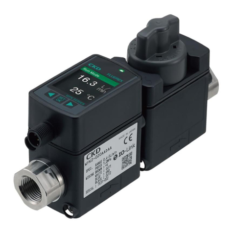
CKD FLUEREX WFK2 Series User manual

CKD
CKD RAPIFLOW FSM2-D Series User manual

CKD
CKD WKF2 Series User manual

CKD
CKD Rapiflow FSM2 Series User manual

CKD
CKD RAPIFLOW FSM3 Series User manual

CKD
CKD Rapiflow FSM2-N Series User manual

CKD
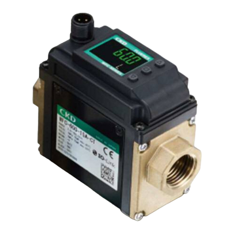
CKD WFC Series User manual

CKD
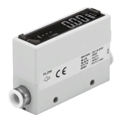
CKD FLUEREX PF Series User manual