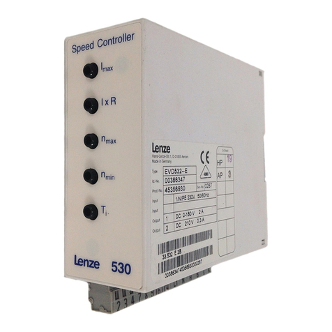
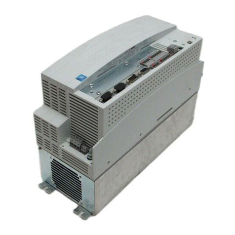
Lenze 4800 User manual

Glossary
Table of keywords
Signal-flow charts
Selection aid
Application examples
Accessories and motors
Automation
Application of brake units
DC bus connection
Troubleshooting and
fault elimination
Maintenance
Configuration
Code table
Commissioning
During operation
Technical data
Installation
Table of contents
Preface and general
information
Safety information
EDS4900U-REG
00408862
Manual
DC speed controller 4800/4900
Show/Hide Bookmarks

Manual 4800 / 4900
Part Content Notes
A
T
able of contents
A
T
a
b
l
e
o
f
c
o
n
t
e
n
t
s
Preface and general information -
P
r
e
f
a
c
e
a
n
d
g
e
n
e
r
a
l
i
n
f
o
r
m
a
t
i
o
n
Safety information
-
BTechnical data
-
B
T
e
c
h
n
i
c
a
l
d
a
t
a
Installation -
CCommissioning
-
C
C
o
m
m
i
s
s
i
o
n
i
n
g
During operation -
DConfiguration
-
D
C
o
n
f
i
g
u
r
a
t
i
o
n
Code table -
ETroubleshooting and fault elimination
-
E
T
r
o
u
b
l
e
s
h
o
o
t
i
n
g
a
n
d
f
a
u
l
t
e
l
i
m
i
n
a
t
i
o
n
Maintenance -
F
D
C
b
u
s
c
o
n
n
e
c
t
i
o
n
F
D
C
b
us connec
t
i
on
GApplication of brake units
HAutomation -
IAccessories and motors -
KSelection aid
-
K
S
e
l
e
c
t
i
o
n
a
i
d
Application examples -
LSignal-flow charts -
MGlossary
Tab le of k ey w or ds -
Explanation: -in the Manual.
All documentation indicated have a material number and the type code in the left upper corner of the cover page.
In part M there is a list with these data.
The controller’s features and data indicated in this Manual are at the state-of-art at the time of print. (The print data is indicated on the inner
cover page of each of part.)
Lenze endeavours to regularly update all documentation to the current technical state. If you should find any deviations, please refer to the
Operating Instructions, which are part of the delivery package, or to your nearest Lenze representative.
Show/Hide Bookmarks

Contents
i
48XX/49XXSHB00399
Part A
1 Preface and general information 1-1..........................
1.1 About these Operating Instructions ... 1-1...........................
1.1.1 Terminology used 1-1....................................
1.2 Scope of delivery 1-1.............................................
1.3 48XX/49XX controller 1-2.........................................
1.3.1 Labelling 1-2...........................................
1.3.2 Application as directed 1-2...............................
1.3.3 Legal regulations 1-3....................................
1.4 EC Directives/Declaration of Conformity 1-4..........................
1.4.1 What is the purpose of EC directives? 1-4..................
1.4.2 What does the CE mark imply? 1-4........................
1.4.3 EC Low-Voltage Directive 1-4.............................
1.4.4 EC Directive Electromagnetic Compatibility 1-6..............
1.4.5 EC Machinery Directive 1-9...............................
2 Safety information 2-1.......................................
2.1 Persons responsible for the safety 2-2..............................
2.2 General safety information 2-3.....................................
2.3 Residual hazards 2-3.............................................
2.4 Layout of the safety information 2-4................................
Part B
3 Technical data 3-1...........................................
3.1 Features 3-1....................................................
3.2 General data / application conditions 3-3............................
3.3 Rated data 3-4..................................................
3.3.1 Mains voltage 400V 3-4..................................
3.3.2 Mains voltage 500V (Variant V014) 3-6.....................
3.4 Dimensions 3-8..................................................
3.4.1 Controller 4902 to 4X09 3-8..............................
3.4.2 Controllers 4811 to 4813, 4911 to 4913 3-9................
4 Installation 4-1..............................................
4.1 Mechanical installation 4-1........................................
4.1.1 Important notes 4-1.....................................
4.2 Electrical installation 4-2..........................................
4.2.1 Protection of persons 4-2................................
4.2.2 Protection of the controller 4-3............................
4.2.3 Screening of the control cables 4-3........................
4.2.4 Earthing of the control electronics 4-4......................
4.2.5 Mains types and conditions 4-4...........................
Show/Hide Bookmarks

Contents
ii 48XX/49XXSHB00399
4.3 Connection 4-5..................................................
4.3.1 Power connection of standard controller 4-6................
4.3.2 Separate supply of the field-current bridge at
a high motor field voltage 4-9.............................
4.3.3 Separate supply for the control electronics 4-11..............
4.3.4 Control connections 4-13.................................
4.3.4.1 Connection of analog signals 4-14...............
4.3.4.2 Connection of digital signals 4-17................
4.3.5 Feedback systems 4-21...................................
4.3.6 Change of the direction of rotation in 2Q operation 4-23.......
4.3.7 Digital frequency selection and encoder emulation 4-24........
4.3.8 Serial interface RS232/485 4-26............................
4.3.9 Fieldbus connection 4-27..................................
4.4 Installation of a CE-typical drive system 4-29..........................
4.4.1 General notes 4-29.......................................
4.4.2 Components of the CE-typical drive system 4-30..............
4.4.3 Measures required 4-30...................................
Part C
5 Commissioning 5-1..........................................
5.1 Initial switch-on 5-1..............................................
5.2 Commissioning of speed-controlled drives 5-2.......................
5.2.1 Wiring recommendation for speed control with tacho 5-3.....
5.2.2 Wiring recommendation for speed control with resolver 5-4....
5.2.3 Speed control with armature voltage feedback 5-5...........
5.3 Commissioning of torque-controlled drives 5-6.......................
5.3.1 Wiring recommendation for torque control with speed limitation 5-7
5.4 Input of the motor data 5-8........................................
5.5 Controller enable 5-9.............................................
5.6 Selection of direction of rotation and quick stop 5-10...................
5.7 Changing the internal control structure 5-12..........................
5.8 Changing the terminal assignment 5-12..............................
6 During operation1)
Show/Hide Bookmarks

Contents
iii
48XX/49XXSHB00399
Part D
7 Configuration 7-1...........................................
7.1 Speed-controlled operation 7-1....................................
7.1.1 Setpoint selection 7-1...................................
7.1.1.1 Main setpoint 7-2.............................
7.1.1.2 Additional setpoint 7-2........................
7.1.1.3 JOG setpoints 7-2............................
7.1.1.4 Master current 7-4............................
7.1.1.5 External torque reduction 7-4..................
7.1.1.6 Acceleration and deceleration times Tir ,Tif 7-6...
7.1.1.7 Limiation of the speed setpoint 7-9..............
7.1.2 Actual value feedback 7-10................................
7.1.2.1 Armature voltage feedback 7-10.................
7.1.2.2 DC tacho feedback 7-11.......................
7.1.2.3 Resolver feedback 7-13........................
7.1.2.4 Incremental encoder feedback 7-13..............
7.1.3 Freely assignable inputs and outputs 7-14...................
7.1.3.1 Freely assignable digital inputs (FDI) 7-14.........
7.1.3.2 Freely assignable digital outputs (FDO) 7-16.......
7.1.3.3 Frei belegbare “analoge” Eingänge (FAE) 7-21.....
7.1.3.4 Freely assignable monitor outputs 7-25...........
7.2 Torque control with speed limitation 7-29.............................
7.3 Digital frequencycoupling 7-31......................................
7.3.1 Master 7-32.............................................
7.3.2 Slave for digital frequency bar 7-34.........................
7.3.3 Slave for digital frequency cascade 7-38.....................
7.3.4 Digital frequency output 7-43..............................
7.3.5 Speed synchronism 7-44..................................
7.3.5.1 Speed-synchrnous running 7-44.................
7.3.5.2 Speed ratio synchronism 7-44...................
7.3.6 Phase synchronisation 7-45................................
7.3.6.1 Phase controller 7-46..........................
7.3.6.2 Phase trimming 7-47...........................
7.3.6.3 Following error limit 7-47.......................
7.4 Additional control functions 7-48....................................
7.4.1 Redundant actual value feedback 7-48......................
7.4.2 Changeable parameter sets 7-50...........................
7.4.3 4Q / 2Q changeover 7-53.................................
7.4.4 Standstill excitation (field heating) 7-54......................
7.4.5 Control of a holding brake 7-55.............................
7.4.5.1 Engage brake 7-57............................
7.4.5.2 Open brake (release) 7-58......................
7.5 Additional function blocks 7-60.....................................
7.5.1 Process controller 7-60...................................
7.5.2 Arithmetic blocks 7-63....................................
7.5.3 Motor potentiometer 7-66.................................
7.5.3.1 Control of the motor potentiometer 7-67..........
7.5.3.2 Memory function of the
motor potentiometer (S&H) 7-68.................
7.5.4 Fixed set-value 7-70......................................
Show/Hide Bookmarks

Contents
iv 48XX/49XXSHB00399
7.5.5 Absolute value generator 7-71.............................
7.5.6 Limitation elements 7-72..................................
7.5.7 PT1 element 7-73........................................
7.5.8 Addition 7-74............................................
7.5.9 Square-wave generator 7-76...............................
7.5.10 Dead-band element 7-77..................................
7.5.11 DT1 element 7-78........................................
7.5.12 Freely assignable comparator 7-79..........................
7.6 Additional control functions 7-82....................................
7.6.1 Additional torque values 7-82..............................
7.6.2 Speed dependent armature current limitation 7-83............
7.6.3 n controller adaptation 7-86................................
7.6.4 S-shaped ramp function generator characteristic 7-87.........
7.6.5 Actual speed filter 7-87....................................
7.6.6 Excitation characteristic 7-88..............................
7.7 Monitoring 7-90...................................................
7.7.1 Change of the monitoring functions 7-90....................
7.7.2 Overload monitoring for the controller (IVt monitoring) 7-94.....
7.7.3 Overload monitoring for the motor (I2Vtmonitoring) 7-95........
7.7.4 Blocking protection for the motor 7-97......................
7.7.5 Mains monitoring 7-99....................................
7.7.6 Monitoring of the serial interface 7-101.......................
7.8 Parameter setting 7-102............................................
7.8.1 Ways of parameter setting 7-102............................
7.8.2 Functions of the operation unit 7-103.........................
7.8.3 Operating modes 7-104....................................
7.8.4 Display functions 7-105....................................
7.9 Code table 7-107..................................................
7.10 Table of attributes 7-133............................................
Show/Hide Bookmarks

Contents
v
48XX/49XXSHB00399
Part E
8 Troubleshooting and fault elimination 8-1.....................
8.1 Troubleshooting 8-1..............................................
8.1.1 Display on the operating unit of the controller 8-1............
8.1.2 Display via LECOM 8-2...................................
8.2 Fault analysis with the history buffer 8-3............................
8.2.1 Structure of the history buffer 8-3..........................
8.3 Fault messages 8-4..............................................
8.4 Reset of fault indications 8-6......................................
8.5 Checking the drive system 8-7.....................................
8.5.1 Checking the motor 8-7..................................
8.5.2 Checking the controller 8-8...............................
9 Maintenance 9-1............................................
9.1 Maintenance 9-1.................................................
9.2 Service addresses 9-1............................................
Part F
10 DC-bus operation1)
Part G
11 Application of brake units1)
Show/Hide Bookmarks

Contents
vi 48XX/49XXSHB00399
Part H
12 Automation 12-1.............................................
12.1 LECOM1 interface 12-1............................................
12.2 LECOM2 interface (option) 12-1.....................................
12.3 LECOM code number 12-1.........................................
12.4 Enable LECOM interface 12-3.......................................
12.4.1 Process data and parameter channel 12-3...................
12.4.2 High precision set and actual values 12-5....................
Part I
13 Accessories 13-1.............................................
13.1 Fuses 13-2.......................................................
13.1.1 Mains fuses 13-3.........................................
13.1.2 Armature fuses 13-4......................................
13.1.3 Internal fuses 13-5........................................
13.1.4 Fuse holder 13-5........................................
13.2 Mains chokes 13-7................................................
13.2.1 Mains chokes for powr connection 13-7.....................
13.2.2 Mains choke for separate supply of the field bridge 13-8.......
13.3 Pre-assembled Lenze system cable 13-10.............................
13.3.1 Resolver connection cable 13-10............................
13.3.2 Incremental encoder connection cable 13-11..................
13.3.3 System cable for digital frequency coupling 13-11..............
13.4 RFI filter 13-12.....................................................
13.4.1 RFI filter for power connection 13-12.........................
13.4.2 RFI filter for fan supply 13-14................................
13.5 Networking accessories 13-15.......................................
13.5.1 Connection elements for optical fibres 13-15..................
13.5.2 Level converter 13-15......................................
Show/Hide Bookmarks

Contents
vii
48XX/49XXSHB00399
Part K
14 Selection aid 14-1............................................
14.1 Assignment of controller and motor 14-1.............................
14.1.1 Selection criteria 14-1.....................................
14.1.2 Armature choke 14-3.....................................
15 Application examples 15-1...................................
15.1 Speed control with armature-voltage feedback 15-2....................
15.2 Speed control with resolver 15-4....................................
15.3 Torque control with speed limitation 15-6.............................
15.4 Current-ratio control 15-8..........................................
15.5 Dancer-position control at an unwinder 15-10..........................
15.6 Hoists 15-13......................................................
15.7 Speed-ratio synchronism 15-15......................................
15.8 Modular box 2215 15-18............................................
15.8.1 Winding drive 15-18.......................................
15.8.2 Positioning drive 15-20.....................................
15.9 Mains isolation 15-23...............................................
15.9.1 Tipping with mains isolation 15-23...........................
15.9.2 Mains switch-off logic 15-25................................
Part L
16 Signal-flow charts 16-1.......................................
Part M
17 Glossary 17-1................................................
18 Index 18-1...................................................
1) This chapter is part of the Lenze documentation structure.
It remains free for the 48XX/49XX DC speed controller.
Show/Hide Bookmarks

Contents
viii 48XX/49XXSHB00399
Show/Hide Bookmarks

EDS4900U--A
00408849
Manual
Part A
Contents
Preface and general information
Safety information
DC speed controller
4800/4900
Show/Hide Bookmarks

The features, data and versions indicated in this Manual met the state of the art at
thetimeofprinting.
(Printing date: inner cover pages of the parts).
In the event of deviations, please see the Operating Instructions or contact Lenze.
revised
Edition of: 01/03/1999
Show/Hide Bookmarks

Preface and general information
1-1
48XX/49XXSHB0399
1 Preface and general information
1.1 About these Operating Instructions ...
-These Operating Instructions are intended for safety-relevant operations on
and with the 48XX/49XX DC controllers. They contain safety information
which must be observed.
-All persons who work on and with 48XX/49XX DC controllers must have the
Operating Instructions available and observe all relevant notes and
instructions.
-The Operating Instructions must always be in a complete and perfectly
readable state.
1.1.1 Terminology used
Controller
In the following, the term ”controller” is used for ” 48XX/49XX DC controllers”.
Drive system
In the following text, the term ”drive system” is used for drive systems with
48XX/49XX DC controllers and other Lenze drive components.
1.2 Scope of delivery
-The scope of delivery includes:
- 1 48XX/49XX DC controller
- 1 Operating Instructions
- 1 Accessory kit with plug-in terminals
-After receipt of the delivery, check immediately whether the scope of
delivery matches the accompanying papers. Lenze does not accept any
liability for deficiencies claimed subsequently. Make a claim for
- visible transport damage immediately to the forwarder.
- visible deficiencies/incompleteness immediately to your Lenze
representative.
Show/Hide Bookmarks

Preface and general information
1-2 48XX/49XXSHB0399
1.3 48XX/49XX controller
1.3.1 Labelling
-Lenze 48XX/49XX controllers are unambiguously designated by the
contents of the nameplate.
-CE mark:
- Conformity with the Low-Voltage Directive
- Conformity with the EMC Directive
-Manufacturer
-LenzeGmbH&CoKG
Postfach 101352
D-31763 Hameln
1.3.2 Application as directed
48XX/49XX controllers
-must only be operated under the conditions prescribed in these
Instructions.
-are components
- for open-loop and closed-loop control of variable speed drives with
separately excited DC motors.
- to be installed into a machine.
- used for assemblies together with other components to form a machine.
-should not be driven together with other DC motors, such as shunt motors
or separately excited motors with a stabilizing series winding, before you
have contacted Lenze.
-are electric units for the installation into control cabinets or similar enclosed
operating housings.
-are not to be used as domestic appliances, but only for industrial purposes.
Drive systems with 48XX/49XX controllers
-comply with the EMC Directive, if they are installed according to the
guidelines for CE-typical drive systems.
-can be used
- on public and non-public mains.
- in industrial premises.
The user is responsible for the compliance of his application with the EC directives.
Any other use shall be deemed inappropriate!
Show/Hide Bookmarks

Preface and general information
1-3
48XX/49XXSHB0399
1.3.3 Legal regulations
Liability
-The information, data and notes in these Operating Instructions met the
state-of-the-art at the time of printing. Claims referring to drive systems
which have already been supplied cannot be derived from the information,
illustrations, and descriptions.
-The specifications, processes, and circuitry described in these Operating
Instructions are for guidance only and must be adapted to your own specific
application. Lenze does not take responsibility for the suitability of the
process and circuit proposals.
-The indications given in these Operating Instructions describe the features
of the product without warranting them.
-Lenze does not accept any liability for damage and operating interference
caused by:
- disregarding these Operating Instructions
- unauthorized modifications to the controller
- operating errors
- improper working on and with the controller
Warranty
-Terms of warranty: see terms of sale and delivery of Lenze GmbH & Co KG.
-Warranty claims must be made immediately after detecting defects or faults.
-The warranty is void in all cases where liability claims cannot be made.
Disposal
The controller consists of different materials.
The following table lists which materials can be recycled and which must be
disposed of.
Material recycle dispose
Metal --
Plastic --
Printed-board assemblies --
Show/Hide Bookmarks

Preface and general information
1-4 48XX/49XXSHB0399
1.4 EC Directives/Declaration of Conformity
1.4.1 What is the purpose of EC directives?
EC directives are issued by the European Council and are intended for the
determination of common technical requirements (harmonization) and certification
procedures within the European Community. At the moment, there are 21 EC
directives for product ranges. The directives are or will be converted to national
laws of the member states. A certification issued by one member state is
automatically valid without any further approval in all other member states.
The texts of the directive are restricted to the essential requirements. Technical
details are or will be determined by European harmonized standards.
1.4.2 What does the CE mark imply?
After a verification, the conformity according to the EC directives is certified by
affixing a CE mark. Within the EC there are no commercial barriers for a product
with the CE mark.
Controllers on their own with the CE mark correspond exclusively to the Low
Voltage Directive. For the compliance with the EMC Directive, only general
recommendations have been issued so far. The CE conformity of the installed
machine remains the responsibility of the user. For the installation of CE-typical
drive systems with the basic version of 48XX/49XX controllers and the variants
V011, V013 and V014, Lenze has already proved the conformity with the EMC
Directive (see chapter 4.4).
1.4.3 EC Low-Voltage Directive
(73/23/EEC)
amended by: CE Mark Directive (93/68/EEC)
General
-The Low-Voltage Directive is effective for all electrical equipment for use
with a rated voltage between 50 V and 1000 V AC and between 75 V and
1500 V DC, and under normal ambient conditions. The use, for instance, of
electrical equipment in explosive atmospheres and electrical parts in
passenger and goods lifts are excepted.
-The objective of the Low-Voltage Directive is to ensure that only electrical
equipment which does not endanger the safety of persons or animals is
placed on the market. It should also be designed to conserve material
assets.
Show/Hide Bookmarks

Preface and general information
1-5
48XX/49XXSHB0399
EC Declaration of Conformity ’99
for the purpose of the EC Low Voltage Directive (73/23/EEC)
amended by: CE Mark Directive (93/68/EEC)
48XX/49XX controllers were developed, designed, and manufactured in
compliance with the EC Directive under the sole responsibility of
Lenze GmbH & Co KG, Postfach 10 13 52, D-31763 Hameln
Considered standards:
Standard
DIN EN 50178
Classification VDE 0160 / 04.98
Electronic equipment for use in electrical power
installations
DIN VDE 0100 Standards for the erection of power installations
EN 60529 IP degrees of protection
IEC 249 / 1 10/86, IEC 249 / 2-15 / 12/89 Base material for printed circuits
IEC 326 / 1 10/90, EN 60097 / 9.93 Printed circuits, printed boards
DIN VDE 0110 /1-2 /1/89 /20/ 8/90 Creepage distances and clearances
Hameln, 01/03/1999
(i.V.Schäfer) (i.A.Tolksdorf)
Product Manager Commissioned for CE
Show/Hide Bookmarks

Preface and general information
1-6 48XX/49XXSHB0399
1.4.4 EC Directive Electromagnetic Compatibility
(89/336/EEC)
amended by: First Amendment Directive (92/31/EEC)
CE Mark Directive (93/68/EEC)
General
-The EC Electromagnetic Compatibility Directive is effective for ”devices”
which may cause electromagnetic interference, or the operation of which
may be impaired by such interference.
-The aim is to limit the generation of electromagnetic interference so that an
operation is possible without interference to radio and telecommunication
systems and other equipment. The devices must also show an appropriate
resistance to electromagnetic interference, to ensure the application as
directed.
-Controllers cannot be evaluated on their own in terms of EMC. Only after
the integration of the controllers into a drive system, can this system be
tested concerning the objectives of the EC EMC Directive and the
compliance with the ”Law about the Electromagnetic Compatibility of
Devices”.
-Lenze has verified the conformity of 48XX/49XX controllers integrated into
certain defined drive systems . In the following, these systems are called
”CE-typical drive systems”(see chapter 4.4).
-The following configurations can now be selected by the user:
- The user himself can determine the system components and their
integration into the drive system, and is then held responsible for the
conformity of the drive.
- The user can select the CE-typical drive systems for which the
manufacturer has already proved the conformity.
Show/Hide Bookmarks

Preface and general information
1-7
48XX/49XXSHB0399
EC Declaration of Conformity ’97 for the purpose of the EC Directive
on Electromagnetic compatibility (89/ 336/EEC)
amended by: First Amendment Directive (92/31/EEC)
CE Mark Directive (93/68/EEC)
48XX/49XXcontrollers cannot be driven in stand-alone operation for the purposes
of the Regulation on Electromagnetic Compatibility (EMVG of 09 November, 1992
and the first Amendment of 08 August, 1995). The EMC can only be verified when
the controller is integrated into a drive system.
Lenze GmbH & Co KG, Postfach 10 13 52, D-31763 Hameln
declares that the described ”CE-typical drive systems”with the basic version of
48XX/49XX controller and the variants V011, V013 and V014 comply with the
above EC Directive.
The conformity evaluation is based on the product standard for drive systems EN
61800-3.
EN 61800-3 EMC product standard including special test methods for electric drives
Generic standards considered:
Generic standard
EN 50081-2 /93 Generic standard for noise emission; part 2: Industrial premises
The noise emission in industrial premises is not limited in EN 61800-3. These generic
standards are used in addition to the requirements of the standard DIN IEC 22G.
EN 50082-2 3/94 Generic standard for noise immunity
part 2: Industrial premises
(The requirements of noise immunity for residential areas were not considered, since
these are less strict.)
Generic standards considered for the test of noise emission:
Generic standard Tes t Limit value
EN 55011 7/92 Radio interferences, housing and mains
Frequency range 0.15 - 1000MHz The noise
emission in industrial premises is not limited in
EN61800-3. These generic standards are
used in addition to the requirements of
EN61800-3.
Class A
for use in
industrial premises
Show/Hide Bookmarks

Preface and general information
1-8 48XX/49XXSHB0399
Generic standards considered for the test of noise emission:
Basic standard Tes t Limit value
EN 61000-4-2 3/95 Electrostatic discharge on housing and heatsink Severity 3
6kV for contact,
8kV clearance
IEC 1000-4-3 2/95 Electromagnetic fields
Frequency range 26-1000MHz
Severity 3
10V/m
ENV 50140 8/93 High-frequency field
Frequency range 80-1000MHz,
80% amplitude modulated
Severity 3
10V/m
Fixed frequency
900MHz with 200Hz, 100 % modulated
10V/m
EN 61000-4-4 3/95 Fast transients,
burst on power terminals
Severity 3
2kV/5kHz
Burst on bus and control cables Severity 4
2kV/5kHz
EN 61000-4-5 10/94 Surge test
Mains cable
Installation class 3
Hameln, 01/03/1999
(i.V.Schäfer) (i.A.Tolksdorf)
Product Manager Commissioned for CE
Show/Hide Bookmarks
This manual suits for next models
1
Table of contents
Other Lenze Controllers manuals

Lenze
Lenze Starttec E71MM402 User manual

Lenze
Lenze 490 Series Parts list manual

Lenze
Lenze P30GAP Series User manual

Lenze
Lenze 9300 Series User manual

Lenze
Lenze M MA Series User manual

Lenze
Lenze SCL series User manual

Lenze
Lenze C 750 User manual

Lenze
Lenze L-force HighLine C 8400 Series User manual

Lenze
Lenze 482 User manual

Lenze
Lenze L-force EDK94AZHN26 User manual