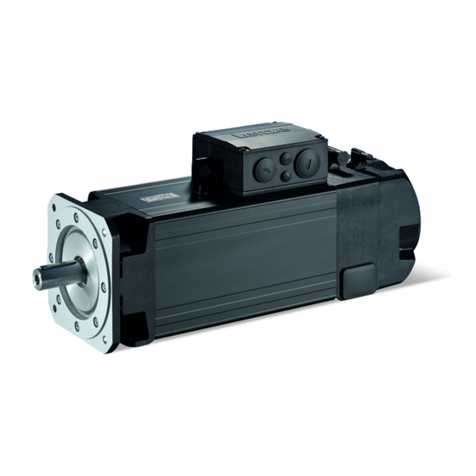
Lenze m850 Technical manual

Servo motors
m850 synchronous servo motor
Project planning EN


Inhalt
About this document5
Document descripon 5
Further documents 5
Notaons and convenons 6
Product informaon 7
Product descripon 7
Idencaon of the products 7
Features 8
The modular system 9
Informaon on project planning 11
Safety instrucons 12
Basic safety instrucons 12
Applicaon as directed 12
Foreseeable misuse 12
Residual hazards 13
Drive dimensioning 14
Final conguraon 18
Environmental condions 18
Informaon on mechanical installaon 19
Important notes 19
Transport 19
Installaon 19
Informaon on electrical installaon 20
Important notes 20
Preparaon 20
Technical data 21
Notes regarding the given data 21
Standards and operang condions 22
Conformies/approvals 22
Protecon of persons and device protecon 22
EMC data 22
Environmental condions 22
Radial forces and axial forces 23
Rated data 25
Inverter mains connecon 400 V, Self-venlated 25
Selecon tables 27
Torque characteriscs 34
Dimensions 39
Basic dimensions 39
Inhalt
3

Product extensions 42
Motor connecon 42
Connecon via ICN connector 42
Brakes 46
Spring-applied brakes 48
Feedback 50
Resolver 51
Absolute value encoder 52
Temperature monitoring 53
Thermal detectors PT1000 53
Product codes 54
Appendix 55
Good to know 55
Approvals/direcves 55
Operang modes of the motor 56
Enclosures 57
Inhalt
4

About this document
Document descripon
This document addresses to all persons who want to carry out any conguraons with the
products described.
The data and informaon compiled in this document serve to support you in the dimensioning
and selecon processes and in carrying out the electrical and mechanical installaon. You will
receive informaon regarding product extensions and accessories.
•The document includes safety instrucons which must be observed.
•All persons working on and with the drives must have the documentaon at hand during
work and observe the informaon and notes relevant for it.
•The documentaon must always be complete and in a perfectly readable state.
NOTICE
Please observe the notes in the following chapters!
▶Safety instrucons ^ 12
▶Informaon on mechanical installaon ^ 19
▶Informaon on electrical installaon ^ 20
Further documents
Informaon and tools with regard to the Lenze products can be found on the
Internet:
hp://www.lenze.com à Download
About this document
Document descripon
Further documents
5

Notaons and convenons
This document uses the following convenons to disnguish dierent types of informaon:
Numeric notaon
Decimal separator Point The decimal point is always used.
Example: 1 234.56
Warning
UL warning UL Are used in English and French.
UR warning UR
Text
Programs » « Soware
Example: »Engineer«, »EASY Starter«
Icons
Page reference ¶Reference to another page with addional informaon
Example: ¶ 16 = see page 16
Documentaon reference ,Reference to another documentaon with addional informaon
Example: , EDKxxx = see documentaon EDKxxx
Layout of the safety instrucons
DANGER!
This note refers to an imminent danger which, if not avoided, may result in death or serious
injury.
WARNING!
This note refers to a danger which, if not avoided, may result in death or serious injury.
CAUTION!
This note refers to a danger which, if not avoided, may result in minor or moderate injury.
NOTICE
This note refers to a danger which, if not avoided, may result in damage to material assets.
About this document
Notaons and convenons
6

Product informaon
Product descripon
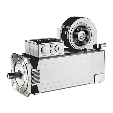
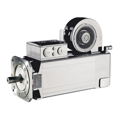
m850 - the servo motor for a medium dynamic performance in compact design.
The compact synchronous servo motor for applicaons in the elds of posioning, robocs,
and packaging technology as well as for handling systems.
In connecon with the Servo-Inverters i700, Servo Drives 9400, and Inverter Drives 8400 Top-
Line, high-performance drive soluons in the torque range from 4.8 to 200 Nm can be
obtained.
Customer benet
•Compact design
•Easy controllability by an advantageous rao of the mass inera of the load and that of the
motor
•Opmum smooth running characteriscs for accurate work results
•The smooth housing surface makes it perfect for the use in the food industry
•Robust resolvers are included as a standard, and multurn SinCos encoders ensure a high
precision
•Easy assembly and easy servicing by SpeedTec connectors with swivel connector boxes
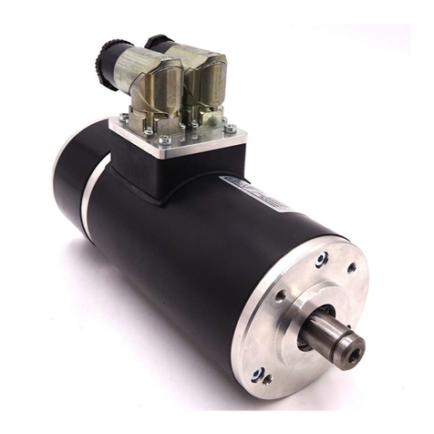
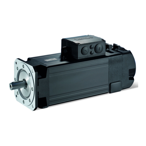
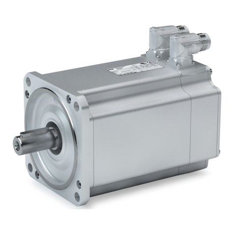
Fig. 1: m850-S140/S3240 synchronous servo motor
Idencaon of the products
Product name of the motor
Product series Type Flange height Overall length Rated speed Motor
mm rpm
m850 - S (synchronous)
120
/
S (short) 3960 m850-S120/S3960
M (medium) 3960 m850-S120/M3960
L (long) 3960 m850-S120/L3960
140
S (short) 3240 m850-S140/S3240
M (medium) 3240 m850-S140/M3240
L (long) 3240 m850-S140/L3240
190
S (short) 3000 m850-S190/S3000
M (medium) 3000 m850-S190/M3000
L (long) 2520 m850-S190/L2520
Product informaon
Idencaon of the products
7

Features
Output flange
Output shaft
Spring-applied brake
Motor connection
Cooling
Feedback
Temperature monitoring
Product informaon
Features
8

The modular system
Values printed in bold are standard designs. Values that are not printed in bold
are potenal extensions, some of them including a surcharge.
Motor m850-S120/S3960 m850-S120/M3960 m850-S120/L3960
Technical data
Rated power kW 2.0 3.1 3.7
Rated torque Nm 4.8 7.4 9.0
Max. torque Nm 14.5 29.0 44.0
Rated speed rpm 3960 3960 3960
Colour Unpainted
Surface and corrosion protecon (called
OKS)
Without
Dierent types of OKS
Output sha
Solid sha without keyway mm 19 x 40
Solid sha with featherkey mm 19 x 40
Sha material Steel
Sha sealing ring material FKM
Output ange mm FF130
Cooling Self-venlated IP54
Self-venlated IP65
Motor connecon ICN connector
Spring-applied brake Without
With
Characterisc torque Nm 18
DC brake voltage V 24
Feedback Resolver
Absolute value encoder
Temperature monitoring PT1000 thermal detector + 2 PTC thermistors
Motor m850-S140/S3240 m850-S140/M3240 m850-S140/L3240
Technical data
Rated power kW 2.9 4.8 5.9
Rated torque Nm 8.5 14.0 17.4
Max. torque Nm 26.0 53.5 80.0
Rated speed rpm 3240 3240 3240
Colour Unpainted
Surface and corrosion protecon (called
OKS)
Without
Dierent types of OKS
Output sha
Solid sha without keyway mm 24 x 50
Solid sha with featherkey mm 24 x 50
Sha material Steel
Sha sealing ring material FKM
Output ange mm FF165
Cooling Self-venlated IP54
Self-venlated IP65
Motor connecon ICN connector
Spring-applied brake Without
With
Characterisc torque Nm 32
DC brake voltage V 24
Feedback Resolver
Absolute value encoder
Temperature monitoring PT1000 thermal detector + 2 PTC thermistors
Product informaon
The modular system
9
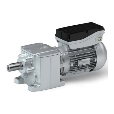
Motor m850-S190/S3000 m850-S190/M3000 m850-S190/L2520
Technical data
Rated power kW 5.0 7.5 9.2
Rated torque Nm 16 24 35
Max. torque Nm 71.0 120 200
Rated speed rpm 3000 3000 2520
Colour Unpainted
Surface and corrosion protecon (called
OKS)
Without
Dierent types of OKS
Output sha
Solid sha without keyway mm 28 x 60
Solid sha with featherkey mm 28 x 60
Sha material Steel
Sha sealing ring material FKM
Output ange mm FF215
Cooling Self-venlated IP54
Self-venlated IP65
Motor connecon ICN connector
Spring-applied brake Without
With
Characterisc torque Nm 100
DC brake voltage V 24
Feedback Resolver
Absolute value encoder
Temperature monitoring PT1000 thermal detector + 2 PTC thermistors
Product informaon
The modular system
10

Informaon on project planning
In order to carry out an accurate drive dimensioning process, you can use our conguring so-
ware, the Drive Soluon Designer.
With the Drive Soluon Designer you can carry out the drive dimensioning process quickly and
with top quality. The soware contains profound and proven experse with regard to drive
applicaons and mechatronic drive components.
Please refer to your competent Lenze sales company.
Informaon on project planning
11

Safety instrucons
Disregarding the following basic safety measures and safety informaon may lead to severe
personal injury and damage to property!
Observe all specicaons of the corresponding documentaon supplied. This is the precondi-
on for safe and trouble-free operaon and for obtaining the product features specied.
Please observe the specic safety informaon in the other secons!
Basic safety instrucons
Personnel
The product must only be used by qualied personnel. IEC 60364 or CENELEC HD 384 dene
the skills of these persons:
•They are familiar with installing, mounng, commissioning, and operang the product.
•They have the corresponding qualicaons for their work.
•They know and can apply all regulaons for the prevenon of accidents, direcves, and
laws applicable at the place of use.
Process engineering
The procedural notes and circuit details described are only proposals. It is up to the user to
check whether they can be adapted to the parcular applicaons. Lenze does not take any
responsibility for the suitability of the procedures and circuit proposals described.
The procedural notes and circuit details described in this document are only proposals. It is up
to the user to check whether they can be adapted to the parcular applicaons. Lenze does
not take any responsibility for the suitability of the procedures and circuit proposals descri-
bed.
Applicaon as directed
•The product must only be actuated under the operang condions and power limits speci-
ed in this documentaon.
•The product meets the protecon requirements of 2014/35/EU: Low-Voltage Direcve.
•The product is not a machine in terms of 2006/42/EC: Machinery Direcve.
•Commissioning or starng the operaon as directed of a machine with the product is not
permied unl it has been ensured that the machine meets the regulaons of the EC
Direcve 2006/42/EC: Machinery Direcve; observe EN 60204−1.
•Commissioning or starng operaon as directed is only permissible if the EMC Direcve
2014/30/EU is complied with.
•The product is not a household appliance, but is only designed as a component for com-
mercial or professional use in terms of EN 61000−3−2.
•The product can be used according to the technical data if drive systems have to comply
with categories according to EN 61800−3.
•In residenal areas, the product may cause EMC interferences. The operator is responsible
for taking interference suppression measures.
•Do not use the built-in brakes as fail-safe brakes. Disrupve factors that cannot be inu-
enced may cause the braking torque to be reduced.
•The product must only be actuated with inverters.
Foreseeable misuse
•Actuate directly on the mains voltage
•Use in potenally explosive areas
•Use in aggressive environments
•Use under water
•Use under radiaon
•Use in generator mode
Informaon on project planning
Safety instrucons
Foreseeable misuse
12

Residual hazards
Even if notes given are taken into consideraon and protecve measures are implemented,
the occurrence of residual risks cannot be fully prevented.
The user must take the residual hazards menoned into consideraon in the risk assessment
for his/her machine/system.
If the above is disregarded, this can lead to severe injuries to persons and damage to prop-
erty!
Protecon of persons
•The product does not provide safety-related funcons.
-A higher-level safety system must be implemented.
-Addional monitoring and protecve equipment complying with the safety regulaons
applicable in each case must be used.
•The power terminals may carry voltage in the switched-o state or when the motor is
stopped.
-Before working, check whether all power terminals are deenergised.
•Voltages may occur on the drive components (e.g. capacive, caused by inverter supply).
-Careful earthing in the marked posions of the components must be carried out.
•Risk of burns may be caused by hot surfaces!
-Provide for a protecon against accidental contact.
-Use the personal protecve equipment or wait unl the components have cooled
down completely!
-Prevent contact with ammable substances.
•There is a risk of injury due to rotang parts.
-Before working on the drive system, ensure that the motor is at a standsll.
•There is a danger of unintenonal starng or electrical shocks!
•Installed brakes are no fail-safe brakes.
- The torque may be reduced by disrupve factors that cannot be inuenced such as
ingressing oil.
Motor protecon
•Design with plug:
-Never disconnect the plug when energised! Otherwise, the plug can be destroyed.
-Switch o power supply and disable inverter prior to disconnecng the plug.
•Installed thermal detectors are no full protecon for the machine.
-If required, limit the maximum current. Parameterise the inverter so that it will be
switched o aer seconds of operaon with I > Irated , especially if there is the danger
of blocking.
-The installed overload protecon does not prevent an overload under any condions.
•The fuses are no motor protecon.
-Use a current-dependent motor protecon switch.
-Use the built-in thermal detectors.
•Too high torques cause a fracon of the motor sha.
-The maximum torques according to catalogue must not be exceeded.
•Lateral forces from the motor sha may occur.
-Align the shas of motor and driven machine exactly to each other.
Informaon on project planning
Safety instrucons
Residual hazards
13

Drive dimensioning
The dimensioning is suitable for:
•kinemac proles
•operang modes S1, S2, S3, S6
•simple linear speed proles, not for S-curves or similar
The following 3 elements are taken into consideraon in the dimensioning process :
Drive funcon
On the basis of the values required for the process that are specied, a drive is selected, for
which all operang points are within the speed-torque characterisc curve of the motor.
As a result, a motor with a suitable speed with an inverter with a sucient maximum current
is selected. Further limits (maximum speed, installaon height...) are specied in tables.
Mechanical strength
On the basis of the forces and torques which build, a drive is selected that has a sucient
mechanic strength (endurance strength for the periodically occurring torques and faque
strength for the sporadically occurring torques).
Thermal dimensioning
For the inverter, the thermal dimensioning process is carried out on the basis of the connu-
ous inverter current or on the basis of the connuous torque from the motor-inverter combi-
naon, which can be reached.
The motor is thermally dimensioned on the basis of the mean speed and the eecve torque.
The mean speed of the drive should not exceed the values specied.
If dimensioning processes are complex or reach limit loads, please refer to your
Lenze branch oce
Operaon chart
S1 operaon S2,S3 and S6 operaon Speed proles
Check operang condions
Dene required input variables
Determine correcon factor
Operang modes and operang me Operang modes and operang me
Ambient temperature and installaon height Ambient temperature and installaon height Ambient temperature and installaon height
Determine motor on the basis of the forces acng
Dene load characterisc for the individual
me segments
Calculaon of the values required for the proc-
ess
Inspect and select motor
Final conguraon
Informaon on project planning
Drive dimensioning
14

Check operang condions
Check
Approvals
Conformity declaraons
Supply voltage
Enclosure
Ambient temperature
Surface protecon
4Conformies/approvals ^ 22
4Environmental condions ^ 18
Dene required input variables
Necessary input variables Note Symbol Unit
Mean speed ulisaon Relang to the load speed nL %
Ambient temperature TU°C
Site altude Amsl H m
Radial force Frad N
Axial force Fax N
Transmission element at the output Gear wheels, sprockets …
Eecve diameter of the transmission element dwmm
Load torque Only with S1, S2, S3, and S6 operang modes MLNm
Load speed Only with S1, S2, S3, and S6 operang modes nLrpm
Short-me maximum torque Emergency o, quick stop, occasional high starng
duty
ML,max Nm
Runme with maximum torque tL%
Determine correcon factor
Operang modes S1, S2, S3, S6, and operang me
Operang mode S1 Operang mode S2 Operang mode S3 Operang mode S6
ED kLED kLED kLED kL
% min % %
100 1.0 10 1.4 - 1.5 15 1.4 - 1.5 15 1.5 - 1.6
30 1.15 - 1.2 25 1.3 - 1.4 25 1.4 - 1.5
60 1.07 - 1.1 40 1.15 - 1.2 40 1.3 - 1.4
90 1.0 - 1.05 60 1.05 - 1.1 60 1.15 - 1.2
4Operang modes of the motor ^ 56
Ambient temperature and installaon height
Ambient temperature Installaon height amsl
< 1000 m < 2000 m
Correcon factor
TUkHkH
≤ 20 °C 1.10 1.04
30 °C 1.05 1.00
40 °C 1.00 0.95
50 °C 0.80 0.76
60 °C 0.60 0.57
Informaon on project planning
Drive dimensioning
15

Determine product on the basis of the forces
Transmission element Gear wheels Sprockets Toothed belt pulleys Narrow V-belt
( depending on the pre-
loading)
( depending on the
preloading)
Addional radial force factor fz
≥ 17 teeth = 1.0 ≥ 20 teeth = 1.0 With belt ghtener= 2.0 -
2.5
1.5 - 2.0
< 17 teeth = 1.15 < 20 teeth = 1.25 Without belt ghtener= 2.5
- 3.0
< 13 teeth = 1.4
Calculaon Check
Radial force Frad N
´
= ´ L,max z
rad
M f
F 2000 dw
Frad ≤ Frad,max
Axial force Fax N Fax ≤ Frad,max
dw Eecve diameter of transmission element
4Radial forces and axial forces ^ 23
Operang mode S1
Check and select servo motor-inverter combinaon
Check Selecon Unit
Output torque MN ≥ ML/ (kL x kH) MN = Nm
Output speed nN ≥ nLnN = rpm
4Rated data ^ 25
Operang modes S2, S3, and S6
Check and select servo motor-inverter combinaon
Check Selecon Unit
Output torque MN ≥ ML/ ( kL x kH) MN = Nm
Output speed (recommendaon) nN ≥ nLnN = rpm
Max. output torque Mmax ≥ MLMmax = Nm
Max. output speed nmax ≥ nLnmax = rpm
All operang points (● )
n [r/min]
M [Nm]
nL
ML
Below the maximum torque character-
isc of the servo motor-inverter combi-
naon, taking ML,max into consideraon
Thermally eecve operang point (○ ) nL
ML/ (kLx kH)
Below the S1 torque characterisc of
the servo motor
4Rated data ^ 25
4Torque characteriscs ^ 34
Informaon on project planning
Drive dimensioning
16

Speed proles
Temporal load characterisc for the individual me segments z
Total me Individual me
segments
Load speed Load speed var-
iaon
Steady-state
load torque
Torque Acceleraon tor-
que
Moment of iner-
a
t ΔtznL,z Δ nL,z ML,z MzMs,z JL
s s rpm rpm Nm Nm Nm kgcm2
Calculaon Symbol Unit
Load cycle duraon
= D
åz
T t
T = s
Calculaon of the values required for the process
Calculaon Symbol Unit
Torque per me segment
p´ D
= + ´ D
L,z
z L,z L
z
2 n
M M J 60 t
Mz = Nm
Maximum torque of the prole MP
,max = max (Mz) MP,max = Nm
Eecve torque
= ´ D £
å2
eff z z
z
1
M M t ,T 1min
T
Me = Nm
Mean speed
= = ´D
å
m L,z L,z z
z
1
n |n | |n | t
T
nm = rpm
Maximum load speed nL,max = max (nL,z) nL,max = rpm
Check and select servo motor-inverter combinaon
Check Preselecon Unit
Output torque MN > Me / kHMN = Nm
Output speed nN ≥ nmnN = rpm
Load-matching factor
for an opmum dynamic performance/
control properes
Requirement kJ = 0.5 ... 10
Opmum kJ = 1 kJ= JL / (JM + JB)
Checking the motor torques
Acceleraon torque
( )
p´ D
= + + ´ ´ D
L,z
S,z z M B
z
2 n
M M J J 60 t
MS,z =
Nm
Eecve torque
= ´ D
å2
S,eff S,z z
z
1
M M t
T
MS,e =
All operang points (● )
n [r/min]
M [Nm]
nL,z
MS,z
Below the maximum torque character-
isc of the servo motor-inverter combi-
naon, taking ML,max into consideraon
Thermally eecve operang point (○ ) nm
MS,e / kH
Below the S1 torque characterisc of
the servo motor
4Rated data ^ 25
4Torque characteriscs ^ 34
Informaon on project planning
Drive dimensioning
17

Final conguraon
Check
Connecon dimensions Output sha
Output ange
Product extensions Brake
Feedback
More informaon about the nal conguraon:
4The modular system ^ 9
4Product extensions ^ 42
Environmental condions
Surface and corrosion protecon (called OKS)
Depending on the ambient condions, the surface and corrosion protecon system (called
OKS) oers tailor-made soluons for opmum protecon.
Various surface coangs ensure that the motors operate reliably even at high air humidity, in
outdoor installaon or in the presence of atmospheric impuries. Any colour from the "RAL
Classic" collecon can be chosen for the top coat.
For the indoor installaon and if no special corrosion protecon is required, the products are
also available unpainted (without OKS).
Surface and corrosion protec-
on (called OKS)
Applicaons Type
without OKS (unpainted) •Indoor installaon, no special corrosion protecon necessary
•Painng by customer
Standard
OKS-G (primed) •Dependent on subsequent top coat applied Oponal
OKS-S (small) •Standard applicaons
•Internal installaon in heated buildings
•Air humidity up to 90 %
OKS-M (medium) •Internal installaon in non-heated buildings
•Covered, protected external installaon
•Air humidity up to 95 %
OKS-L (large) •External installaon
•Air humidity above 95 %
•Chemical industrial plants
•Food industry
Surface and corrosion
protecon (called OKS)
Corrosivity category Surface coang Colour Coang thickness
DIN EN ISO 12944-2 Design
without OKS (unpainted)
OKS-G (primed) •2K PUR priming coat 60 ... 90 µm
OKS-S (small) Comparable to C1 •2K-PUR top coat
•Standard: RAL 7012
•Oponal: RAL Classic
80 ... 120 µm
OKS-M (medium) Comparable to C2 •2K PUR priming coat
•2K-PUR top coat
110 ... 160 µm
OKS-L (large) Comparable to C3 140 ... 200 µm
Informaon on project planning
Final conguraon
Environmental condions
18

Informaon on mechanical installaon
Important notes
•You must install the product according to specicaons in the chapter "standard and oper-
ang" condions.
4Standards and operang condions ^ 22
•The technical data and the data regarding the supply condions can be found on the
nameplate and in this documentaon.
•Observe the informaon relang to the surface and corrosion protecon.
4Environmental condions ^ 18
•Ambient media − especially chemically aggressive ones − may damage sha sealing rings,
lacquers and plascs. If required, contact your responsible Lenze subsidiary.
NOTICE
Bearing damage caused by unbalance!
Shas with keyway are balanced with a half featherkey!
▶Balance transmission elements with a half featherkey!
Transport
•Ensure appropriate handling.
•Make sure that all component parts are safely mounted. Secure or remove loose compo-
nent parts.
•Only use safely xed transport aids (e.g. eye bolts or support plates).
•Do not damage any components during the transport.
•Avoid electrostac discharge on electronic components and contacts.
•Avoid impacts.
•Check the carrying capacity of the hoists and load handling devices. The weights can be
obtained from the shipping documents.
•Secure the load against pping and falling down.
•Standing under a suspended load is forbidden.
Installaon
•Avoid resonances with the rotaonal frequency and double mains frequency.
•The mounng surfaces must be plane, torsionally rigid and free from vibraons.
•The mounng areas must be suited to absorb the forces and torques generated during
operaon.
•Ensure an unhindered venlaon.
•For versions with a fan, keep a minimum distance of 10 % from the outside diameter of the
fan cover in intake direcon.
Informaon on mechanical installaon
Installaon
19

Informaon on electrical installaon
Important notes
DANGER!
Hazardous voltage!
On the power connecons even when disconnected from the mains: residual voltage >60 V!
▶Disconnect the product from the mains and wait unl the motor is at a standsll.
▶Make sure that the product is safely isolated from supply!
•When working on energised products, comply with the applicable naonal accident pre-
venon regulaons.
•Carry out the electrical installaon in compliance with the relevant regulaons (e.g. cable
cross-secons, fuses, PE connecon).
•The manufacturer of the system or machine is responsible for adherence to the limits
required in connecon with EMC legislaon.
Preparaon
The notes for the electrical connecon can be found in
in the terminal box (if motors with a terminal box are used).
the connecon plan (if motors with connectors are used).
EMC-compliant wiring
The EMC-compliant wiring is described in detail in the documentaon of the
Lenze inverters.
Informaon on electrical installaon
Preparaon
20
Other manuals for m850
3
Table of contents
Other Lenze Engine manuals

Lenze
Lenze g500-S Guide

Lenze
Lenze IE3 g500-B Technical manual

Lenze
Lenze M Series User manual

Lenze
Lenze g500-B Guide

Lenze
Lenze Smart Motor m300 Guide

Lenze
Lenze L-force GST User manual

Lenze
Lenze M Series Operating instructions

Lenze
Lenze SDS Series User manual

Lenze
Lenze MCA Series Guide

Lenze
Lenze MSEMA 080-32 Series Guide
Popular Engine manuals by other brands

Siemens
Siemens 2KG13 Information on safety and commissioning

Detroit Diesel
Detroit Diesel DDFP Series Operation and maintenance instruction manual

Volvo Penta
Volvo Penta TAD1381VE Operator's manual

WilTec
WilTec 62000 Operation manual

MULTIPLEX modell
MULTIPLEX modell HIMAX A 2825 Series instructions

Scania
Scania DC13 XPI Operator's manual