Lenze SDS Series User manual

BA 13.0011−EN
.CD(
Ä.CD(ä
Operating Instructions
SDS..
l
SDSGS
Synchronous servo motors

l
2 BA 13.0011−EN 1.0
,Please read these instructions before you start working!
Follow the enclosed safety instructions.
0Fig. 0Tab. 0

Contents i
l3
BA 13.0011−EN 1.0
1 About this documentation 5. . . . . . . . . . . . . . . . . . . . . . . . . . . . . . . . . . . . . . . . . . . . . . . . . .
1.1 Document history 5. . . . . . . . . . . . . . . . . . . . . . . . . . . . . . . . . . . . . . . . . . . . . . . . . . . .
1.2 Conventions used 6. . . . . . . . . . . . . . . . . . . . . . . . . . . . . . . . . . . . . . . . . . . . . . . . . . . .
1.3 Abbreviations used 6. . . . . . . . . . . . . . . . . . . . . . . . . . . . . . . . . . . . . . . . . . . . . . . . . . .
1.4 Terminology used 6. . . . . . . . . . . . . . . . . . . . . . . . . . . . . . . . . . . . . . . . . . . . . . . . . . . .
1.5 Notes used 7. . . . . . . . . . . . . . . . . . . . . . . . . . . . . . . . . . . . . . . . . . . . . . . . . . . . . . . . . .
2 Safety instructions 8. . . . . . . . . . . . . . . . . . . . . . . . . . . . . . . . . . . . . . . . . . . . . . . . . . . . . . . . .
2.1 General safety instructions for drive components 8. . . . . . . . . . . . . . . . . . . . . . . . . .
2.2 Application as directed 10. . . . . . . . . . . . . . . . . . . . . . . . . . . . . . . . . . . . . . . . . . . . . . . .
2.3 Improper use 10. . . . . . . . . . . . . . . . . . . . . . . . . . . . . . . . . . . . . . . . . . . . . . . . . . . . . . . .
2.4 Residual hazards 11. . . . . . . . . . . . . . . . . . . . . . . . . . . . . . . . . . . . . . . . . . . . . . . . . . . . .
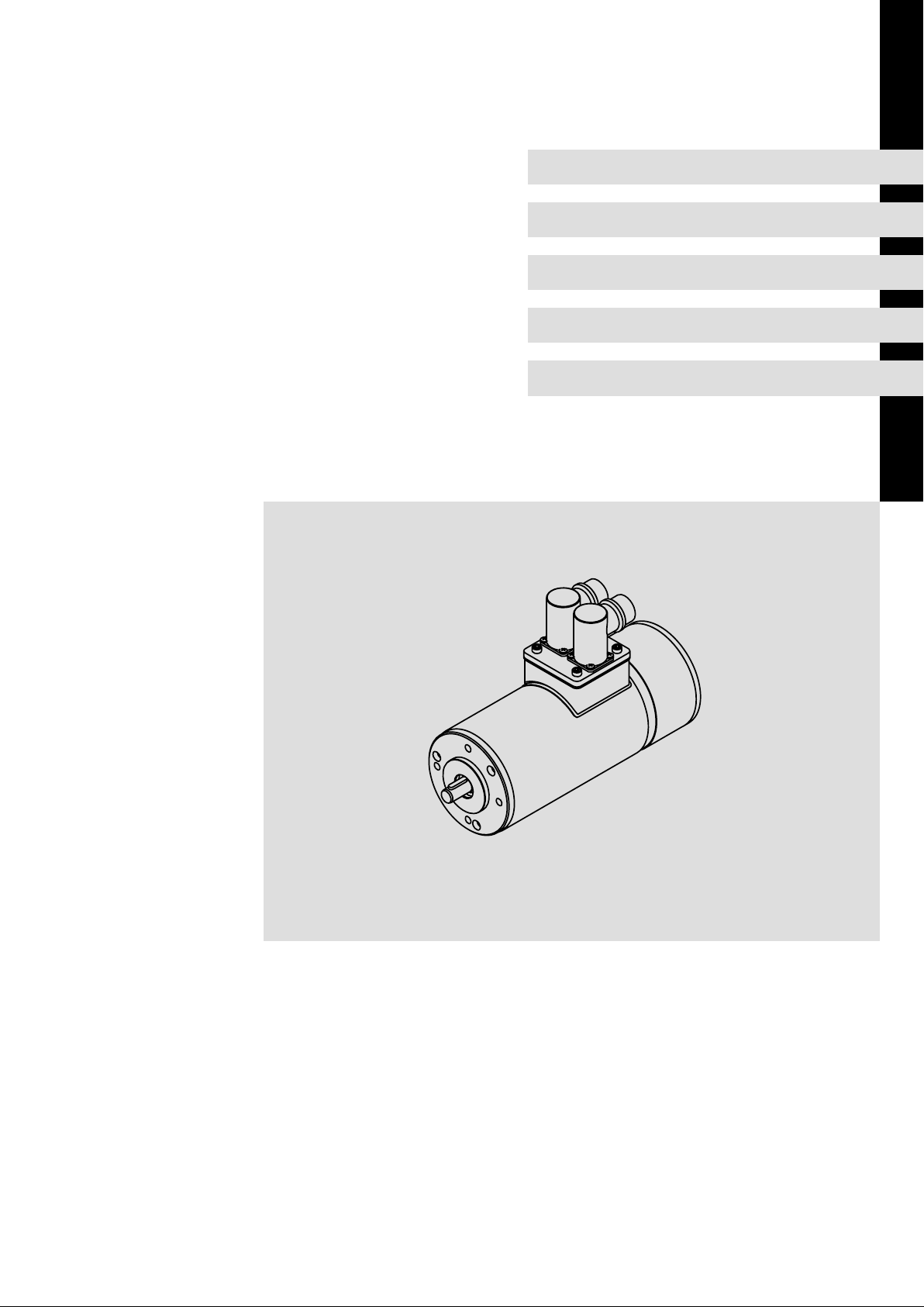
3 Product description 12. . . . . . . . . . . . . . . . . . . . . . . . . . . . . . . . . . . . . . . . . . . . . . . . . . . . . . . .
3.1 Identification 12. . . . . . . . . . . . . . . . . . . . . . . . . . . . . . . . . . . . . . . . . . . . . . . . . . . . . . . .
3.1.1 Nameplate 12. . . . . . . . . . . . . . . . . . . . . . . . . . . . . . . . . . . . . . . . . . . . . . . . . .
3.1.2 Product key 15. . . . . . . . . . . . . . . . . . . . . . . . . . . . . . . . . . . . . . . . . . . . . . . . . .
4 Technical data 16. . . . . . . . . . . . . . . . . . . . . . . . . . . . . . . . . . . . . . . . . . . . . . . . . . . . . . . . . . . .
4.1 General data and operating conditions 16. . . . . . . . . . . . . . . . . . . . . . . . . . . . . . . . .
4.1.1 General data 16. . . . . . . . . . . . . . . . . . . . . . . . . . . . . . . . . . . . . . . . . . . . . . . .
4.2 Operating conditions 17. . . . . . . . . . . . . . . . . . . . . . . . . . . . . . . . . . . . . . . . . . . . . . . . .
4.3 Dimensions 18. . . . . . . . . . . . . . . . . . . . . . . . . . . . . . . . . . . . . . . . . . . . . . . . . . . . . . . . . .
4.4 Rated data 19. . . . . . . . . . . . . . . . . . . . . . . . . . . . . . . . . . . . . . . . . . . . . . . . . . . . . . . . . .
4.5 Rated data 20. . . . . . . . . . . . . . . . . . . . . . . . . . . . . . . . . . . . . . . . . . . . . . . . . . . . . . . . . .
4.5.1 Shaft loads 22. . . . . . . . . . . . . . . . . . . . . . . . . . . . . . . . . . . . . . . . . . . . . . . . . .
5 Mechanical installation 23. . . . . . . . . . . . . . . . . . . . . . . . . . . . . . . . . . . . . . . . . . . . . . . . . . . . .
5.1 Preparation 23. . . . . . . . . . . . . . . . . . . . . . . . . . . . . . . . . . . . . . . . . . . . . . . . . . . . . . . . . .
5.2 Assembly of built−on accessories 23. . . . . . . . . . . . . . . . . . . . . . . . . . . . . . . . . . . . . . . .
5.3 Installation 24. . . . . . . . . . . . . . . . . . . . . . . . . . . . . . . . . . . . . . . . . . . . . . . . . . . . . . . . . .
5.4 Holding brake (option) 24. . . . . . . . . . . . . . . . . . . . . . . . . . . . . . . . . . . . . . . . . . . . . . . .
5.4.1 Important notes 24. . . . . . . . . . . . . . . . . . . . . . . . . . . . . . . . . . . . . . . . . . . . . .
5.4.2 Permanent magnet holding brakes 26. . . . . . . . . . . . . . . . . . . . . . . . . . . . . .
5.4.3 Spring−applied holding brakes 28. . . . . . . . . . . . . . . . . . . . . . . . . . . . . . . . . .
6 Electrical installation 30. . . . . . . . . . . . . . . . . . . . . . . . . . . . . . . . . . . . . . . . . . . . . . . . . . . . . . .
6.1 Important notes 30. . . . . . . . . . . . . . . . . . . . . . . . . . . . . . . . . . . . . . . . . . . . . . . . . . . . . .
6.2 Wiring according to EMC 31. . . . . . . . . . . . . . . . . . . . . . . . . . . . . . . . . . . . . . . . . . . . . .
6.3 Connection plan 32. . . . . . . . . . . . . . . . . . . . . . . . . . . . . . . . . . . . . . . . . . . . . . . . . . . . . .

Contentsi
l4 BA 13.0011−EN 1.0
7 Commissioning and operation 33. . . . . . . . . . . . . . . . . . . . . . . . . . . . . . . . . . . . . . . . . . . . . . .
7.1 Important notes 33. . . . . . . . . . . . . . . . . . . . . . . . . . . . . . . . . . . . . . . . . . . . . . . . . . . . . .
7.2 Before switching on 34. . . . . . . . . . . . . . . . . . . . . . . . . . . . . . . . . . . . . . . . . . . . . . . . . .
7.2.1 Servo motor parameters 34. . . . . . . . . . . . . . . . . . . . . . . . . . . . . . . . . . . . . . .
7.3 Functional test 35. . . . . . . . . . . . . . . . . . . . . . . . . . . . . . . . . . . . . . . . . . . . . . . . . . . . . . .
7.4 Functional test 35. . . . . . . . . . . . . . . . . . . . . . . . . . . . . . . . . . . . . . . . . . . . . . . . . . . . . .
7.5 During operation 35. . . . . . . . . . . . . . . . . . . . . . . . . . . . . . . . . . . . . . . . . . . . . . . . . . . . .
8 Maintenance/repair 36. . . . . . . . . . . . . . . . . . . . . . . . . . . . . . . . . . . . . . . . . . . . . . . . . . . . . . .
8.1 Important notes 36. . . . . . . . . . . . . . . . . . . . . . . . . . . . . . . . . . . . . . . . . . . . . . . . . . . . . .
8.2 Maintenance intervals 36. . . . . . . . . . . . . . . . . . . . . . . . . . . . . . . . . . . . . . . . . . . . . . . .
8.3 Repair 37. . . . . . . . . . . . . . . . . . . . . . . . . . . . . . . . . . . . . . . . . . . . . . . . . . . . . . . . . . . . . .
9 Troubleshooting and fault elimination 38. . . . . . . . . . . . . . . . . . . . . . . . . . . . . . . . . . . . . . .

About this documentation
Document history
1
l5
BA 13.0011−EN 1.0
1 About this documentation
Contents
ƒThe present operating instructions are intended for safe working on and with the
motors. They contain safety instructions that must be observed.
ƒAll personnel working on and with the motors must have the operating instructions
available during work and observe the information and notes relevant for them.
ƒThe operating instructions must always be complete and in a perfectly readable
state.
If the information and notes provided in this documentation do not meet your
requirements, please refer to the controller and/or gearbox documentation.
ITip!
Documentation and software updates for further Lenze products can be found
on the Internet in the "Services & Downloads" area under
http://www.Lenze.com
Validity
This documentation is valid for synchronous servo motors:
Type Designation
SDSGSLL
035, 047, 056, 063
Synchronous servo motors
Target group
This documentation is directed at qualified skilled personnel according to IEC 60364.
Qualified skilled personnel are persons who have the required qualifications to carry out
all activities involved in installing, mounting, commissioning, and operating the product.
1.1 Document history
Material no. Version Description
13314243 1.0 07/2009 TD09 First edition of the operating instructions, separate
from three−phase AC motors

About this documentation
Conventions used
1
l
6 BA 13.0011−EN 1.0
1.2 Conventions used
This documentation uses the following conventions to distinguish different types of
information:
Type of information Identification Examples/notes
Spelling of numbers
Decimal separator Point In general, the decimal point is used.
For instance: 1234.56
Warnings
UL warnings JAre only provided in English.
Icons
Page reference ^Reference to another page with additional
information
For instance: ^16 = see page 16
1.3 Abbreviations used
Abbreviations
PrRated power Fr1/Fr2 Permissible radial load
MnRated torque FaPermissible axial load
IrRated current nrRated speed
URated voltage mMot Motor weight (mass)
FRated frequency Nmax. speed
JMoment of inertia Mmax. torque
wAngular velocity MKCharacteristic torque
Itot Total moment of inertia MLLoad torque
QFriction energy WEnergy
UResulting supply voltage LCable length
UBRated voltage of the brake IBRated current of the brake
Lphase Phase inductance RUV Stator resistance
1.4 Terminology used
Term In this text used for
Motor Synchronous motor, versions according to product key, ^15
Controller Any servo inverter
Drive system Drive systems with servo motors and other Lenze drive components

About this documentation
Notes used
1
l7
BA 13.0011−EN 1.0
1.5 Notes used
The following pictographs and signal words are used in this documentation to indicate
dangers and important information:
Safety instructions
Structure of safety instructions:
}Danger!
(characterises the type and severity of danger)
Note
(describes the danger and gives information about how to prevent dangerous
situations)
Pictograph and signal word Meaning
{Danger!
Danger of personal injury through dangerous electrical voltage.
Reference to an imminent danger that may result in death or
serious personal injury if the corresponding measures are not
taken.
}Danger!
Danger of personal injury through a general source of danger.
Reference to an imminent danger that may result in death or
serious personal injury if the corresponding measures are not
taken.
(Stop!
Danger of property damage.
Reference to a possible danger that may result in property
damage if the corresponding measures are not taken.
Application notes
Pictograph and signal word Meaning
)Note! Important note to ensure troublefree operation
ITip! Useful tip for simple handling
,Reference to another documentation
Special safety instructions and application notes for UL
Pictograph and signal word Meaning
JWarnings!
Safety note or application note for operating UL approved
devices in UL approved systems.
The operation of the drive system may not be UL compliant if
the corresponding measures are not taken.

Safety instructions
General safety instructions for drive components
2
l
8 BA 13.0011−EN 1.0
2 Safety instructions
2.1 General safety instructions for drive components
(in accordance with Low−Voltage Directive 2006/95/EC)
At the time of dispatch, the drive components are in line with the latest state of the art and
can be regarded as operationally safe.
Scope
The following safety instructions generally apply to Lenze drive components.
The product−specific safety and application notes given in this documentation must be
observed!
General hazards
}Danger!
Disregarding the following basic safety measures may lead to severe personal
injury and damage to material assets!
ƒLenze drive components ...
... must only be applied as directed.
... must never be commissioned if visibly damaged.
... must never be technically modified.
... must never be commissioned if incompletely mounted.
... must never be operated without the required covers.
ƒAll specifications of the corresponding enclosed documentation must be observed.
This is vital for a safe and trouble−free operation as well as for achieving the specified
product features.
ƒOnly qualified, skilled personnel is permitted to work on and with Lenze drive
components.
According to IEC 60364 / CENELEC HD 384, these are persons who ...
... are familiar with the installation, mounting, commissioning, and operation of the
product.
... have the qualifications required for their occupation.
... know and are able to apply all national regulations for the preventions of accidents,
directives and laws applicable on site.

Safety instructions
General safety instructions for drive components
2
l9
BA 13.0011−EN 1.0
Transport, storage
ƒTransport and storage in a dry, low−vibration environment without aggressive
atmosphere; preferably in the packaging provided by the manufacturer.
– Protect against dust and shocks.
– Comply with climatic conditions according to the technical data.
ƒBefore transport
– Check that all transport locking devices are mounted.
– Tighten all transport aids.
)Note!
Do not apply extra loads to the product as the transport aids (such as eye bolts
or bearing plates) are designed for the weight of the motor only (refer to the
catalogue for the weight).
Mechanical installation
ƒInstall the product according to the regulations of the corresponding
documentation. In particular observe the section "Operating conditions" in the
chapter "Technical data".
ƒProvide for a careful handling and avoid mechanical overload. During handling
neither bend components, nor change the insulation distances.
Electrical installation
ƒCarry out the electrical installation according to the relevant regulations (e. g. cable
cross−sections, fusing, connection to the PE conductor). Additional notes are
included in the documentation.
ƒThe documentation contains notes for the EMC−compliant installation (shielding,
earthing, arrangement of filters and installation of the cables). The manufacturer of
the system or machine is responsible for the compliance with the limit values
required in connection with EMC legislation.
ƒFor compliance with the limit values for radio interference emission at the site of
installation, the components − if specified in the technical data − have to be mounted
in housings (e. g. control cabinets). The housings have to enable an EMC−compliant
installation. In particular observe that for example control cabinet doors preferably
have a circumferential metallic connection to the housing. Reduce openings or
cutouts through the housing to a minimum.
ƒOnly plug in or remove pluggable terminals in the deenergised state!
Commissioning
ƒIf required, you have to equip the system with additional monitoring and protective
devices in accordance with the respective valid safety regulations (e. g. law on
technical equipment, regulations for the prevention of accidents).
ƒBefore commissioning remove transport locking devices and keep them for later
transports.

Safety instructions
Application as directed
2
l
10 BA 13.0011−EN 1.0
2.2 Application as directed
Low−voltage machines are no household appliances, they are designed as components for
industrial or professional use in terms of IEC/EN 61000−3−2 only.
They comply with the harmonised standards of the series IEC/EN60034.
Low−voltage machines are components for installation into machines as defined in the
Machinery Directive 2006/42/EC. Commissioning is prohibited until the conformity of the
end product with this directive has been established (follow i. a. IEC/EN 60204−1).
It is only permissible to use low−voltage machines with IP23 protection or less outdoors if
special protective measures are taken.
The integrated brakes must not be used as safety brakes. It cannot be ruled out that
interference factors which cannot be influenced cause a brake torque reduction.
ƒDrives
– ... must only be operated under the operating conditions and power limits
specified in this documentation.
– ... comply with the protection requirements of the EC Low−Voltage Directive.
Any other use shall be deemed inappropriate!
2.3 Improper use
ƒDo not operate the motors
– ... in explosion−protected areas
– ... in aggressive environments (acid, gas, vapour, dust, oil)
– ... in water
– ... in radiation environments

Safety instructions
Residual hazards
2
l11
BA 13.0011−EN 1.0
2.4 Residual hazards
Protection of persons
ƒDo not use the integrated brakes as fail−safe brakes. It cannot be ruled out that
certain disruptive factors that cannot be influenced such as oil ingress due to a
defective shaft sealing ring at the drive end may reduce the braking torque.
Motor protection
ƒIntegrated temperature sensors do not provide full protection for the machine. If
necessary, limit the maximum current. Parameterise the controller so that the
motor will be switched off with I > Irafter a few seconds of operation, especially if
there is a risk of blocking.
ƒIf deviations from normal operation occur, e.g. increased temperature, noise,
vibration, determine the cause and, if necessary, contact the manufacturer. If in
doubt, switch off the low−voltage machine.
ƒOverload protection does not protect against overloading under all conditions.

Product description
Identification
Nameplate
3
l
12 BA 13.0011−EN 1.0
3 Product description
3.1 Identification
3.1.1 Nameplate
LKA−SDSGS−001.iso

Product description
Identification
Nameplate
3
l13
BA 13.0011−EN 1.0
1General information
1.1 Manufacturer 1.2 Applicable conformity declarations and approvals
2Data on the complete drive system
2.1 Drives 2.2 Type of drive
3Inverter data
3.1 Inverter 3.6 Voltage / I=Imax
3.2 Type of inverter 3.7 Fieldbus
3.3 FW 3.8 RS232
3.4 HW 3.9 I/O
3.5 Input
4Encoder data
4.1 Encoder / feedback 4.3 Encoder voltage
4.2 Type of encoder 4.4 Indicated voltage
5Gearbox data
5.1 Gearbox 5.4 Ratio
5.2 Gearbox type 5.5 Lubricant
5.3 Torque M2[Nm] 5.6 Type of lubricant
6Motor data
6.1 Motor 6.9 nmax (mechanical)
6.2 Motor type 6.10 C86 code
6.3 Motor type 6.11 Circuit, rated voltage
6.4 Rated power [kW] 6.12 Rated frequency
6.5 Degree of protection 6.13 Rated current
6.6 Rated torque 6.14 Rated speed
6.7 Operating mode 6.15 Insulation class of the winding
6.8 cos j6.16 Temperature sensor
7Brake data
7.1 Brake 7.3 Voltage, current, braking torque
7.2 Type of brake 7.4 Material number
8Production data
8.1 Customer order number 8.4 Serial number
8.2 Year of manufacture 8.5 Bar code
8.3 Ident no. of the drive

Product description
Identification
Nameplate
3
l
14 BA 13.0011−EN 1.0
Gearbox
Pos. Contents
1 Manufacturer
2Gearbox type
3 Manufacturing date
4Commission number
5Torque M2[Nm]
6 Ratio
7CE designation
Brakes
Reference to installed brake
Pos. Contents
1 Type / size of brake
2Voltage [V] DC
3Electrical power [W]
4Braking torque [Nm]
5Material number

Product description
Identification
Product key
3
l15
BA 13.0011−EN 1.0
3.1.2 Product key
Synchronous servo motors S D S G S LL LLL −L L
0
1
2
3
4
5
6
7
8
Product key legend
0Product group SSmall drives
1Current type DThree−phase AC current
2Ventilation S Self ventilation (cooling by convection and radiation)
3Design/housing G Smooth and round housing
4Machine type SSynchronous machine
5Built−on accessories RS
AG
BA
BS
Resolver
Absolute value encoder
Brake and sin/cos absolute value encoder
Brake and resolver
6Frame size 035, 047, 056, 063
7Overall length 1
2
3
short
medium
long
8Number of pole pairs 2

Technical data
General data and operating conditions
General data
4
l
16 BA 13.0011−EN 1.0
4 Technical data
4.1 General data and operating conditions
4.1.1 General data
Conformity and approval
Conformity
CE 2006/95/EC Low−Voltage Directive
Approvals
UL/CSA File no. E210321
Protection of persons and equipment
Degree of protection See nameplate
Degrees of protection only apply to horizontal installation
All unused plug−in connections must be sealed with
protective caps or dummy connectors.
Earth leakage current IEC/EN 61800−5−1 > 3.5 mA Observe stipulations and safety
instructions!
Total fault current < 100 mA
Earth−leakage circuit breakers of type B can be used.
Thermal class F (155 °C) IEC 60034 Exceeding the temperature limit weakens or destroys the
insulation
Insulation resistance IEC/EN 61800−5−1 < 2000 m site altitude: overvoltage category III
> 2000 m site altitude: overvoltage category II
Protective measures Short circuit on the motor side, earth fault when switching on
the mains and during operation, motor overtemperature
(input for PTC or thermal contact, I2t monitoring)
Permissible voltage IEC/EN 60034−25 1.5 kV peak value
10 kV/ms speed of increase
Vibration Up to 2.0 g (20 m/s2) without resonance excitation, e.g. of the
fan.
EMC
Noise emission IEC/EN 61800−3 Depending on the controller, see documentation for the
controller.
Noise immunity

Technical data
General data and operating conditions
General data
4
l17
BA 13.0011−EN 1.0
4.2 Operating conditions
Ambient conditions
Climatic
Transport IEC/EN 60721−3−2 2K3 (−20 ... +70 °C)
Storage IEC/EN 60721−3−1 1K3 (−20 ... +60 °C) < 3 months
1K3 (−20 ... +40 °C) > 3 months
Operation IEC/EN 60721−3−3 Without brake −15 °C ... +40 °C
With brake −10 °C ... +40 °C Without power reduction
> +40 °C With power reduction see,
catalogue
Site altitude < 1000 m amsl − without power reduction
> 1000 m amsl < 4000m amsl with power reduction, see
catalogue
Humidity Average relative humidity 85 %, without condensation
Electrical
The motor connection type depends on the controller
Length of motor cable See inverter instructions
Length of cable for speed feedback
Mounting conditions
Mechanical
Mounting positions
Motor Suitable for all mounting positions
Geared motor Only for the ordered mounting position, see nameplate
ƒOther application conditions require a power derating or torque reduction using the
factors listed in table 2 and 3 (see below).
Power derating
Power derating for other application conditions
Cooling air temperature [°C] 40 45 50 55 60
Power derating [kυ]1.00 0.95 0.90 0.83 0.77
Installation height above sea level
[m]
1000 2000 3000 4000 5000
Power derating [kh] 1.00 0.92 0.83 0.77 0.67
Tab. 1

Technical data
Dimensions
General data
4
l
18 BA 13.0011−EN 1.0
4.3 Dimensions
Motor type Frame size a1 b1j7 c1 dk6 d2 e1 f1 G g1 g2 i2 K
BS
SDSGSLL 035−22 IEC56C80 79 50 12 9 M3 65 2.5 65 95 58 20 224
SDSGSLL 047−22 IEC56C80 79 50 12 9 M3 65 2.5 75 101 58 20 253
SDSGSLL 047−22 IEC63C90 89 60 12 11 M4 75 2.5 75 101 58 23 256
SDSGSLL 056−22 IEC63C90 89 60 12 11 M4 75 2.5 85 106 58 23 271
SDSGSLL 063−22 IEC71C105 104 70 12 14 M5 85 2.5 95 111 58 30 283
Motor type Frame size k1 k3 k4 L l1 l2 s1 t U X Weight
RS AG XX BS BA approx.
kg
SDSGSLL 035−22 IEC56C80 169 180 138 204 225 20 3 14 M5 10.2 3 95 1.9 − 2.9
SDSGSLL 047−22 IEC56C80 189 200 156 233 244 20 3 14 M5 10.2 3 115 3.0 − 4.0
SDSGSLL 047−22 IEC63C90 489 200 156 233 244 23 3 18 M5 12.5 4 115 3.0 − 4.0
SDSGSLL 056−22 IEC63C90 196 207 163 248 260 23 3 18 M5 12.5 4 120 4.0 − 5.5
SDSGSLL 063−22 IEC71C105 199 214 168 253 268 30 2.5 25 M6 16 5 130 5.3 − 6.7
Tab. 2 Dimensions in mm

Technical data
Rated data
General data
4
l19
BA 13.0011−EN 1.0
4.4 Rated data
ƒThe most important rated data of the motor are indicated on the nameplate.
– Further technical data can be obtained from the catalogues.
ƒThe indicated torques and weights are guide values for the selection of the
transmission elements and foundations.
ƒThe rated data indicated on the nameplate refer to operation with Lenze servo
inverters of the 9300 and 9400 series at an inverter input voltage (mains voltage) of
400 V.
)Note!
ƒThe motors can also be connected to inverters others than servo inverters of
the 9300 and 9400 series:
– Depending on the modulation and control performance of the inverter it
might be necessary to derate the power if excessive temperatures are
detected (see Tab. 1).

Technical data
Rated data
General data
4
l
20 BA 13.0011−EN 1.0
4.5 Rated data
SDSGSLL 035−22
Unit Rated voltage [V] AC
13 25 30 210 360
Rated power [W] 140 140 140 140 140
Rated frequency [Hz] 100 100 100 100 100
Rated current [A] 8.4 4.4 4.0 0.56 0.36
Power factor cosj1 1 1 1 1
Rated speed [rpm] 3000 3000 3000 3000 3000
Rated torque [Nm] 0.45 0.45 0.45 0.45 0.45
Degree of protection 54/55 54/55 54/55 54/55 54/55
Thermal class F F F F F
Maximum current [A] 47.5 26.5 22 3.3 2.05
Demagnetising current [A] 86 48 40 6.0 3.8
Maximum torque [Nm] 1.6 1.15 2.0 2.46 2.15
Maximum speed [rpm] 6000 6000 6000 6000 6000
RUV at 20°C [W] 0.22 0.72 1.10 46.6 116.4
Lphase [mH] 0.18 0.59 0.85 37.6 96.3
Moment of inertia [kg cm2] 0.221 0.221 0.221 0.221 0.221
SDSGSLL 047−22
Unit Rated voltage [V] AC
25 30 210 360
Rated power [W] 170 210 250 250
Rated frequency [Hz] 67 83 100 100
Rated current [A] 6.2 6.2 1.1 0.71
Power factor cosj1 1 1 1
Rated speed [rpm] 2000 2500 3000 3000
Rated torque [Nm] 0.8 0.8 0.8 0.8
Degree of protection 54/55 54/55 54/55 54/55
Thermal class F F F F
Maximum current [A] 31 31 5.5 3.55
Demagnetising current [A] 41 41 7.5 4.8
Maximum torque [Nm] 2.0 2.4 3.9 3.9
Maximum speed [rpm] 6000 6000 6000 6000
RUV at 20°C [W] 0.61 0.61 18.6 46.8
Lphase [mH] 0.846 0.846 25.7 63.85
Moment of inertia [kg cm2] 0.301 0.301 0.301 0.301
This manual suits for next models
6
Table of contents
Other Lenze Engine manuals

Lenze
Lenze L-force GST User manual

Lenze
Lenze MSEMA Series Technical manual

Lenze
Lenze g500-H Guide

Lenze
Lenze MCS 06C60 Guide

Lenze
Lenze MCA Series Guide

Lenze
Lenze MQA Series Technical manual

Lenze
Lenze g500-H45 Technical manual

Lenze
Lenze g500 Series User manual

Lenze
Lenze M55BH063S04 Guide

Lenze
Lenze g500 Series User manual