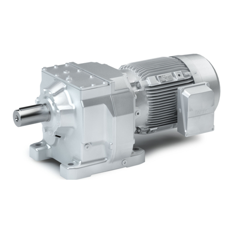
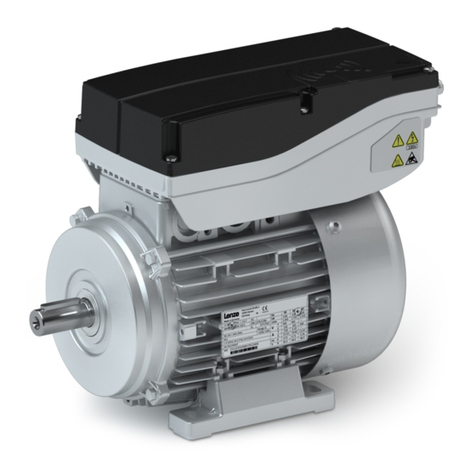
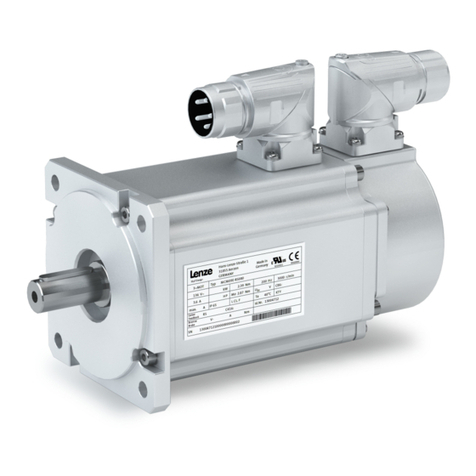
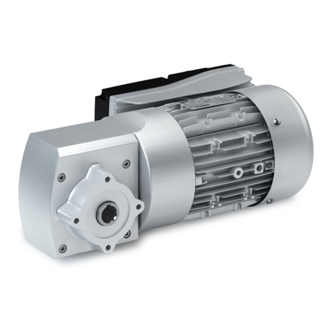
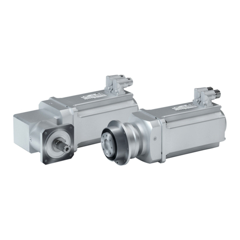
Lenze L-force GST User manual

BA 12.0023−EN
.A0=
Ä.A0=ä
Operating Instructions
GLL
l
GST, GFL, GKS/GKL, GKR, GSS
Gearbox
L−force Geared Motors

l
2 BA 12.0023−EN 6.0
Product key
LLL LL − L L L L L L
0
1
2
3
4
5
6
7
Legend for product key
0Gearbox type GST
GFL
GKS/GKL
GKR
GSS
Helical gearbox
Shaft−mounted helical gearbox
Helical−bevel gearbox
Bevel gearbox
Helical−worm gearbox
1Gearbox size
2Number of stages
3Input design A
D
E
G
I
K
M
N
P
Q
R
S
T
U
W
Servo motor, asynchronous, totally enclosed fan−cooled
Disco variable speed drive
Three−phase AC motor with Motec
SDS three−phase AC motor
Servo motor, asynchronous, internal cooling
Compact unit
Three−phase AC motor
Gearbox with bearing flange for IEC standard motors or NEMA
DC permanent magnet motor 13.12x/SGS
DC motor, smooth housing, MGFQU/MGFQK
DC motor, ribbed housing, MGFRK
Servo motor, synchronous, totally enclosed fan−cooled
DC shunt motor 13.5xx
Three−phase AC motor 13.71x/13.75x
Gearbox with free drive shaft
4Output design G
V
H
S
Solid shaft, smooth (without keyway)
Solid shaft (with keyway)
Hollow shaft
Hollow shaft with shrink disk
5A
B
C
D
Foot mounting, with centring
Foot mounting, without centring
Without foot mounting, with centring
Without foot mounting, without centring
6R
K
l
Without flange
With flange (through holes)
With flange (threaded holes)
7Drive size
Examples
Motor
Mounting flange/free input
shaft
Mech. variable speed drive
071C32
1C
071−1202C

l3
BA 12.0023−EN 6.0
Document history
Material number Version Description
00 390 375 1.0 11/1995 TD09 1st edition for pilot series
00 393 076 1.0 03/1997 TD09 Completely revised
00 393 076 1.0 04/2000 TD09 Addendum to Ch. 4.4.1 Preparatory work
Updated illustrations for Ch. 4.4.10 Gearbox with breather
00 407 986 1.0 12/2000 TD09 Completely revised
Revised product key and position of system blocks
Supplement with gearbox 03
Ch. 4.4.12 Gearbox with compensation container in mounting position C
Ch. Spare parts list compensation container
Changes of lubricant quantities
00 425 604 1.0 08/2001 TD09 Ch. 4.4.8 Assembly of shrink disk cover: new
Ch. 4.4.9 Assembly of hoseproof hollow shaft cover: new
Supplement with GKR 05
00 425 604 2.0 11/2001 TD09 Changes of lubricant quantities
00 460 708 1.0 12/2002 TD09 Changes of nameplates
Supplement with GKR 06
Change of company’s name
00 460 708 2.0 02/2003 TD09 Supplement − Warning in Ch. 4
00 476 711 2.1 10/2003 TD09 Changes: Product key and position of system blocks
Supplement with Ch. 7.2.2, Roller bearing grease and Ch. 7.2.3, Lubricant table
13124908 3.0 11/2005 TD09 New "geared motor" nameplate included.
Revision of the lubricant table
13166718 4.0 08/2006 TD09 Revision of the nameplate marking
New nameplate: CSA/UL version
Supplement with Ch. Mounting the shrink disc with a rotating cover
Revision of the Ch. Position of the breathing, oil filler plug and oil drain plug
Addition of the drive sizes: 3F; 4E; 6C and 7C
13290892 5.0 03/2009 TD09 Complete revision
.A0= 6.0 10/2009 TD09 Conversion from G−motion to L−force Geared Motors
Supplement − Ch. Condensation drain hole
0Fig. 0Tab. 0

l
4 BA 12.0023−EN 6.0
Nameplate
Geared motor
Standard version
Nameplate GNG−001.iso
CSA/UL version
Nameplate GNG−002.iso

l5
BA 12.0023−EN 6.0
Pos. Contents
1 Production site
2Motor type / standard
3Gearbox type
4Motor type
5Technical data Ratio
Rated torque
Rated speed (rated frequency)
6Mounting position / position of the system modules
7 Lubricant
8Brake data (if fitted) Type
AC/DC brake voltage
Braking torque, electrical power consumption
9Feedback /pulse encoder or resolver data (if fitted)
10 Production data Order number
Material number
Serial number
Additional customer data
11 Bar code
12 Rectifier identifier
13 Information on operating mode
14 Additional information on
motor
Thermal class
Degree of protection
Motor protection
15 Applicable conformities and approvals
16 Rated data for 5
0 Hz, 60 Hz and 87 Hz
Hz = output frequency
kW = motor power
HP = motor power Horsepower
r/min. = motor speed
V = motor voltage
A = motor current
h= motor efficiency
cos j= motor power factor
C 86 = Code 0086, selection code for operation on servo inverter
17 Application factor (data if < 1.0)
18 Year of manufacture/ week of manufacture
19 Additional information
20 ALR = Ampere locked rotor
21 Inverter duty motor PWM

l
6 BA 12.0023−EN 6.0
Gearbox
N and W version M and N version with motor K (compact unit) and D (Disco) − version
Nameplate GST−004.iso Nameplate GST−005.iso Nameplate GKS−006.iso
Ver-
sion
N and W version M and N version with motor K (compact unit) and D (Disco) − version
Pos.
1 Production site / country; www.Lenze.com
2Gearbox type Gearbox and motor type
3Year of manufacture/ week of manufacture
4Mounting position / position of the system modules
5Rated torque/rated speed Rated torque
Rated speed/rated frequency
Application factor (data if < 1.0)
Operating frequency
Rated torque/rated speed
6 Lubricant
7 Ratio
8Material number / serial number
9Bar code
10 Order number
11 Additional information
12 Additional customer data

l7
BA 12.0023−EN 6.0
Mounting position (A−F) and position of system modules (1−6)
GST Terminal box, Motec, connector: 2, 3, 4, 5
Without terminal box, Motec, connector: 0
A B C D E F
GFL Solid shaft: 6
Hollow shaft: 0
Hollow shaft with shrink disc: 1, 6
Foot: 3, 4
Without foot: 0
Terminal box, Motec, connector: 2, 3, 4, 5
Without terminal box, Motec, connector: 0
A B C D E F
GKS/GSS/GKL Solid shaft: 3, 5, 8 (3+5)
Hollow shaft: 0
Hollow shaft with shrink disc: 3, 5
Flange: 3, 5, 8 (3+5)
Without flange: 0
Terminal box, Motec, connector: 2, 3, 4, 5
Without terminal box, Motec, connector: 0
A B C D E F
GKR Solid shaft: 3, 5, 8 (3+5)
Hollow shaft: 0
Hollow shaft with shrink disc: 3, 5
Flange: 3, 5, 8 (3+5)
Without flange: 0
Terminal box, Motec, connector: 2, 3, 4, 5
Without terminal box, Motec, connector: 0
A B C D E F

Contentsi
l8 BA 12.0023−EN 6.0
1 Preface and general information 10. . . . . . . . . . . . . . . . . . . . . . . . . . . . . . . . . . . . . . . . . . . .
1.1 About these Operating Instructions 10. . . . . . . . . . . . . . . . . . . . . . . . . . . . . . . . . . . . .
1.2 Terminology used 10. . . . . . . . . . . . . . . . . . . . . . . . . . . . . . . . . . . . . . . . . . . . . . . . . . . .
1.3 Scope of supply 10. . . . . . . . . . . . . . . . . . . . . . . . . . . . . . . . . . . . . . . . . . . . . . . . . . . . . .
1.4 Lenze drive systems 11. . . . . . . . . . . . . . . . . . . . . . . . . . . . . . . . . . . . . . . . . . . . . . . . . . .
1.4.1 Labelling 11. . . . . . . . . . . . . . . . . . . . . . . . . . . . . . . . . . . . . . . . . . . . . . . . . . . .
1.5 Legal regulations 11. . . . . . . . . . . . . . . . . . . . . . . . . . . . . . . . . . . . . . . . . . . . . . . . . . . . .
2 Safety instructions 12. . . . . . . . . . . . . . . . . . . . . . . . . . . . . . . . . . . . . . . . . . . . . . . . . . . . . . . . .
2.1 Personnel responsible for safety 12. . . . . . . . . . . . . . . . . . . . . . . . . . . . . . . . . . . . . . . .
2.2 General safety information 12. . . . . . . . . . . . . . . . . . . . . . . . . . . . . . . . . . . . . . . . . . . .
2.3 Notes used 13. . . . . . . . . . . . . . . . . . . . . . . . . . . . . . . . . . . . . . . . . . . . . . . . . . . . . . . . . .
3 Technical data 14. . . . . . . . . . . . . . . . . . . . . . . . . . . . . . . . . . . . . . . . . . . . . . . . . . . . . . . . . . . .
3.1 Product features 14. . . . . . . . . . . . . . . . . . . . . . . . . . . . . . . . . . . . . . . . . . . . . . . . . . . . .
3.2 Transport weights 15. . . . . . . . . . . . . . . . . . . . . . . . . . . . . . . . . . . . . . . . . . . . . . . . . . . .
3.3 General data and operating conditions 16. . . . . . . . . . . . . . . . . . . . . . . . . . . . . . . . .
3.3.1 Temperatures 16. . . . . . . . . . . . . . . . . . . . . . . . . . . . . . . . . . . . . . . . . . . . . . . .
3.3.2 Ambient conditions 16. . . . . . . . . . . . . . . . . . . . . . . . . . . . . . . . . . . . . . . . . . .
3.3.3 Paint 16. . . . . . . . . . . . . . . . . . . . . . . . . . . . . . . . . . . . . . . . . . . . . . . . . . . . . . .
4 Mechanical installation 17. . . . . . . . . . . . . . . . . . . . . . . . . . . . . . . . . . . . . . . . . . . . . . . . . . . . .
4.1 Transport equipment for gearbox 17. . . . . . . . . . . . . . . . . . . . . . . . . . . . . . . . . . . . . .
4.2 Storage 19. . . . . . . . . . . . . . . . . . . . . . . . . . . . . . . . . . . . . . . . . . . . . . . . . . . . . . . . . . . . .
4.3 Backstop 19. . . . . . . . . . . . . . . . . . . . . . . . . . . . . . . . . . . . . . . . . . . . . . . . . . . . . . . . . . . .
4.4 Mounting 21. . . . . . . . . . . . . . . . . . . . . . . . . . . . . . . . . . . . . . . . . . . . . . . . . . . . . . . . . . .
4.4.1 Preparation 21. . . . . . . . . . . . . . . . . . . . . . . . . . . . . . . . . . . . . . . . . . . . . . . . . .
4.4.2 General information about the assembly of drive systems 22. . . . . . . . . . .
4.4.3 Assembly of transmission elements on solid shafts 22. . . . . . . . . . . . . . . .
4.4.4 Attachment of motors to gearboxes with bearing housing
(input design N) 23. . . . . . . . . . . . . . . . . . . . . . . . . . . . . . . . . . . . . . . . . . . . . .
4.4.5 Coupling hubs 24. . . . . . . . . . . . . . . . . . . . . . . . . . . . . . . . . . . . . . . . . . . . . . .
4.4.6 Attachment of gearboxes with hollow shafts and keyway 27. . . . . . . . . .
4.4.7 Mounting the shrink disc with a rotating cover 29. . . . . . . . . . . . . . . . . . . .
4.4.8 Mounting the fixed cover 33. . . . . . . . . . . . . . . . . . . . . . . . . . . . . . . . . . . . . .
4.4.9 Mounting the hoseproof hollow shaft cover 34. . . . . . . . . . . . . . . . . . . . . .
4.4.10 Gearboxes with breathers 35. . . . . . . . . . . . . . . . . . . . . . . . . . . . . . . . . . . . .
4.4.11 Breather position, oil filling screw and drain plug 36. . . . . . . . . . . . . . . . . .
4.4.12 Gearbox with compensation container for mounting position C 48. . . . .
Contents i
l9
BA 12.0023−EN 6.0
5 Electrical installation 50. . . . . . . . . . . . . . . . . . . . . . . . . . . . . . . . . . . . . . . . . . . . . . . . . . . . . . .
5.1 Motor connection 50. . . . . . . . . . . . . . . . . . . . . . . . . . . . . . . . . . . . . . . . . . . . . . . . . . . .
5.2 Motor options 50. . . . . . . . . . . . . . . . . . . . . . . . . . . . . . . . . . . . . . . . . . . . . . . . . . . . . . .
6 Commissioning and operation 51. . . . . . . . . . . . . . . . . . . . . . . . . . . . . . . . . . . . . . . . . . . . . . .
6.1 Before switching on 51. . . . . . . . . . . . . . . . . . . . . . . . . . . . . . . . . . . . . . . . . . . . . . . . . .
6.2 During operation 51. . . . . . . . . . . . . . . . . . . . . . . . . . . . . . . . . . . . . . . . . . . . . . . . . . . . .
7 Maintenance 52. . . . . . . . . . . . . . . . . . . . . . . . . . . . . . . . . . . . . . . . . . . . . . . . . . . . . . . . . . . . .
7.1 Maintenance intervals 52. . . . . . . . . . . . . . . . . . . . . . . . . . . . . . . . . . . . . . . . . . . . . . . .
7.2 Maintenance operations 54. . . . . . . . . . . . . . . . . . . . . . . . . . . . . . . . . . . . . . . . . . . . . . .
7.2.1 Opening the condensation drain hole 54. . . . . . . . . . . . . . . . . . . . . . . . . . . .
7.2.2 Roller bearing grease 55. . . . . . . . . . . . . . . . . . . . . . . . . . . . . . . . . . . . . . . . . .
7.2.3 Table of lubricants 56. . . . . . . . . . . . . . . . . . . . . . . . . . . . . . . . . . . . . . . . . . . .
7.2.4 Replacing the lubricant 59. . . . . . . . . . . . . . . . . . . . . . . . . . . . . . . . . . . . . . . .
7.2.5 Lubricant quantity 59. . . . . . . . . . . . . . . . . . . . . . . . . . . . . . . . . . . . . . . . . . . .
7.2.6 Amount of lubricant for combined mounting positions 65. . . . . . . . . . . . .
7.3 Repair 66. . . . . . . . . . . . . . . . . . . . . . . . . . . . . . . . . . . . . . . . . . . . . . . . . . . . . . . . . . . . . .
7.4 Spare parts list, geared motors 67. . . . . . . . . . . . . . . . . . . . . . . . . . . . . . . . . . . . . . . . .
7.5 Spare parts list, gearbox and gearbox with variable speed drive 68. . . . . . . . . . . . .
7.6 Order form 69. . . . . . . . . . . . . . . . . . . . . . . . . . . . . . . . . . . . . . . . . . . . . . . . . . . . . . . . . .
8 Troubleshooting and fault elimination 70. . . . . . . . . . . . . . . . . . . . . . . . . . . . . . . . . . . . . . .
9 Disposal 71. . . . . . . . . . . . . . . . . . . . . . . . . . . . . . . . . . . . . . . . . . . . . . . . . . . . . . . . . . . . . . . . . .

Preface and general information
About these Operating Instructions
1
l
10 BA 12.0023−EN 6.0
1 Preface and general information
1.1 About these Operating Instructions
ƒThese Operating Instructions are intended for safety−relevant operations on and
with the gearboxes GLL. They contain safety instructions which must be observed.
ƒAll personnel working on and with the gearboxes GLL must have the Operating
Instructions available and observe the information and notes relevant for them.
ƒThe Operating Instructions must always be complete and perfectly readable.
1.2 Terminology used
Term In the following text used for
Gearboxes Gearbox of product family GLL
Drive system Drive system with gearboxes GLL and other Lenze drive components
1.3 Scope of supply
ƒThe drive systems are combined individually according to a modular design. The
scope of supply can be obtained from the pertinent papers.
ƒAfter receipt of the supply, check immediately whether it corresponds with the
accompanying papers. Lenze does not grant any warranty for subsequent claims.
Claim for
– visible transport damages immediately to the forwarder.
– visible deficiencies / incompleteness immediately to the responsible Lenze
subsidiary / agency.

Preface and general information
Lenze drive systems
Labelling
1
l11
BA 12.0023−EN 6.0
1.4 Lenze drive systems
1.4.1 Labelling
Lenze drive systems are uniquely designated by the content of their nameplates.
Manufacturer
Lenze Drives GmbH
Postfach 10 13 52
D−31763 Hameln
Application as directed
ƒLenze drive systems
– are intended for use in machinery and plant,
– must only be used for the purposes ordered and confirmed,
– must only be operated under the ambient conditions prescribed in these
Operating Instructions,
– must not be operated beyond their corresponding power limits.
Any other use shall be deemed inappropriate!
1.5 Legal regulations
Liability
ƒThe information, data, and notes in the Operating Instructions were state of the art
at the time of printing. Claims referring to drive systems which have already been
supplied cannot be derived from the information, illustrations, and descriptions.
ƒWe do not accept any liability for damage and operating interference caused by:
– inappropriate use,
– unauthorised modifications to the drive system,
– improper working on and with the drive system,
– operating faults,
– disregarding the Operating Instructions.
Warranty
ƒConditions of warranty: see terms of sale and delivery of Lenze Drives GmbH.
ƒWarranty claims must be made to Lenze immediately after detecting the deficiency
or fault.
ƒThe warranty is void where liability claims cannot be made.

Safety instructions
Personnel responsible for safety
2
l
12 BA 12.0023−EN 6.0
2 Safety instructions
2.1 Personnel responsible for safety
Operator
ƒAn operator is any natural or legal person who uses the drive system or on behalf of
whom the drive system is used.
ƒThe operator or his safety officer must ensure
– that all relevant regulations, instructions and legislation are observed.
– that only qualified personnel work with and on the drive system.
– that the personnel have the Operating Instructions available for all corresponding
operations.
– that non−qualified personnel are prohibited from working with and on the drive
system.
Skilled personnel
Skilled personnel are persons who − because of their education, experience, instructions,
and knowledge about corresponding standards and regulations, rules for the prevention
of accidents, and operating conditions − are authorised by the person responsible for the
safety of the plant to perform the required actions and who are able to recognise potential
hazards.
(See IEC 364, definition of skilled personnel)
2.2 General safety information
ƒThis safety information does not claimed to be complete. In case of questions and
problems, please contact your Lenze representative.
ƒAt the time of delivery the drive system meets the state of the art and ensures safe
basic operation.
ƒThe drive system is a source of danger for persons, for the drive system itself, and for
other material assets of the operator, if
– unqualified personnel works with and on the drive system,
– the drive system is used inappropriately.
ƒThe drive systems must be designed such that they perform their functions after
proper installation and with application as directed in fault−free operation and that
they do not cause hazards for persons. This also applies for their interaction with the
complete plant.
ƒBe sure to take appropriate measures in the case of drive system failure so that no
material damage occurs.
ƒOperate the drive system only when it is in a proper state.
ƒRetrofittings, modifications, or redesigns of the drive system are basically
prohibited. Lenze must be contacted in all cases.

Safety instructions
Notes used
2
l13
BA 12.0023−EN 6.0
2.3 Notes used
The following pictographs and signal words are used in this documentation to indicate
dangers and important information:
Safety instructions
Structure of safety instructions:
}Danger!
(characterises the type and severity of danger)
Note
(describes the danger and gives information about how to prevent dangerous
situations)
Pictograph and signal word Meaning
{Danger!
Danger of personal injury through dangerous electrical voltage.
Reference to an imminent danger that may result in death or
serious personal injury if the corresponding measures are not
taken.
}Danger!
Danger of personal injury through a general source of danger.
Reference to an imminent danger that may result in death or
serious personal injury if the corresponding measures are not
taken.
(Stop!
Danger of property damage.
Reference to a possible danger that may result in property
damage if the corresponding measures are not taken.
Application notes
Pictograph and signal word Meaning
)Note! Important note to ensure troublefree operation
ITip! Useful tip for simple handling
,Reference to another documentation

Technical data
Product features
3
l
14 BA 12.0023−EN 6.0
3 Technical data
ƒThe most important technical data are given on the nameplate (structure and
contents ^ page 4 to 6).
ƒThe product catalogues contain further technical data.
3.1 Product features
Design
Drive systems have a modular design.
They consist of:
ƒReduction gearboxes
– Helical gearboxes
– Shaft−mounted helical gearboxes
– Helical−worm gearboxes
– Helical−bevel gearboxes
– Bevel gearbox
ƒVariable speed drives
ƒMotors
Mode of operation
ƒTorque and speed conversion
Product family Pre−stage 1st stage 2nd stage 3rd stage
Helical gearbox
Helical
Helical
Helical −−−
Shaft−mounted helical gearbox −−−
Helical−bevel gearbox Bevel Helical
Bevel gearbox −−− −−−
Helical−worm gearbox Helical Worm −−−
ƒThe torque reaction must be supported in a suitable manner.

Technical data
Transport weights
3
l15
BA 12.0023−EN 6.0
3.2 Transport weights
Gearbox size Geared motors
Motor frame sizes
063−LL 071−LL 080−LL 090−LL 100−LL 112−LL
GLL03 < 10 < 10
GLL04 < 30 < 30 < 40 < 50
GLL05 < 50 < 50 < 60 < 60 < 70
GLL06 < 70 < 70 < 80 < 90 < 100 < 125
GLL07 < 125 < 125 < 150 < 150 < 175
GLL09 < 200 < 200 < 225 < 225 < 250
GLL11 < 350 < 375 < 375 < 400
GLL14 < 625 < 650 < 650
Gearbox size Geared motors
Motor frame sizes
Gearboxes
132−LL 160−LL 180−LL 200−LL 225−LL
GLL04 < 30
GLL05 < 50
GLL06 < 70
GLL07 < 200 < 250 < 150
GLL09 < 275 < 325 < 475 < 550 < 250
GLL11 < 425 < 450 < 600 < 700 < 850 < 400
GLL14 < 700 < 750 < 850 < 950 < 1100 < 625
Tab. 1 Transport weights in [kg]; values may differ from table value

Technical data
General data and operating conditions
Temperatures
3
l
16 BA 12.0023−EN 6.0
3.3 General data and operating conditions
3.3.1 Temperatures
The permissible temperature range is determined by the following:
ƒThe lubricant specifications in connection with the expected oil temperatures in
operation (see chapter 7.1 and nameplate).
ƒThe thermal class of the motor considering the motor temperature expected during
operation (see nameplate and/or Operating Instructions of the motor).
The operating temperature is determined by the power loss, the ambient temperature and
the cooling system!
(Stop!
With mineral oil, the upper temperature limit for continuous operation is 80°C,
with synthetic oil and shaft sealing rings made of FP (Viton) 100°C. If these
temperatures are exceeded, measures are necessary to reduce the
temperature, see chapter 8.
}Danger!
Depending on the operating conditions, surfaces may be hot, provide
protection against accidental contact.
3.3.2 Ambient conditions
ƒGearboxes are protected against dust and spray water.
ƒMotors according to their enclosure (see nameplate and/or Operating Instructions
for the motor).
ƒAmbient media − especially chemically aggressive − can destroy shaft seals and
coatings (plastic). Abrasive media endanger shaft seals.
ƒThe installation site of the drive must be free of shocks and vibration.
ƒDirt of dust deposits impede the heat dissipation (cooling).
3.3.3 Paint
Lenze offers paints with different resistance characteristics for drive systems. Since the
resistance may be reduced when the paint coat is damaged, defects in paint work (e.g.
through transport or assembly) must be removed professionally to reach the required
corrosion resistance.

Mechanical installation
Transport equipment for gearbox
4
l17
BA 12.0023−EN 6.0
4 Mechanical installation
}Danger!
Only transport the drive with transport equipment or hoists which are suitable
for this load (see transport weights, chapter 3.2). Ensure a safe fixing. Avoid
shocks!
The motors attached to the gearbox are partially equipped with eyebolts.
These are exclusively determined for motor/gearbox mounting and
dismounting and must not be used for the complete geared motor!
4.1 Transport equipment for gearbox
As of size 05, Lenze GST, GKS and GSS gearboxes are as standard available with a transport
thread for eye bolts according to DIN 580. The thread position can be seen from the below
figures. The eye bolts are not contained in the delivery package.
GSTXX−1 GSTXX−2/3 GSSXX−2/3 and GKSXX−3/4
Fig. 1 Eye bolt position
)Note!
As standard, threads are delivered with plug screws. The plug can be easily
removed, e.g. by using a screwdriver blade. For the thread size and load
carrying capacity of the eye bolt, please see Tab. 2.

Mechanical installation
Transport equipment for gearbox
4
l
18 BA 12.0023−EN 6.0
Gearbox size Thread max. load carrying capacity of eye bolt to DIN 580
single−strand two−strand (45°)
45°
GT−GNG−005.iso/dms
05 M8 140 100
06 M8 140 100
07 M12 340 240
09 M16 700 500
11 M20 1200 860
14 M20 1200 860
Tab. 2 Load carrying capacity of eye bolt in kg
}Danger!
Completely screw in eye bolts. They must be located evenly and all−over!
If possible, the eye bolts should be loaded vertically in the direction of the
screw axis! Diagonal or lateral tension reduces the load carrying capacity!
Observe data in DIN 580!
For reaching a load direction as vertical as possible (highest load carrying
capacity), use additional, suitable straps, if necessary. Secure straps against
getting out of place!
(Stop!
Observe load carrying capacity!
Staying under floating load is prohibited!

Mechanical installation
Storage
4
l19
BA 12.0023−EN 6.0
4.2 Storage
If you do not install the gearbox immediately, ensure appropriate conditions of storage.
ƒGenerally
– Store gearbox in dry, clean (dust−free) and sunlight−protected indoor rooms.
– The storage location must be free of vibration and shocks (Veff < 0.2 mm/s) to
avoid roller bearing downtime damage.
– Temperature changes with condensate formation must be avoided.
– Do not activate breather element to prevent air exchange with ambient air.
ƒUp to one year:
– Store the gearbox with breather such that the breather screw is located at the top.
– Shafts and bright surfaces are delivered with protection against corrosion. Spots
with defective corrosion protection must be re−treated.
– On motors with condensation drain holes (option), the plug screw must be
removed (see chapter 4.4.1).
ƒOver one year, up to two years:
– Before storage, shafts and bright surfaces must be provided with a long−term
anticorrosive agent (e.g. Anticorit BW 366 from the company Fuchs).
– Set up gearbox in mounting position A.
– Fill gearbox with oil grade filled in (see nameplate) up to the top breather / oil
bore. Then mount plug screw or breather element (do not activate) again.
4.3 Backstop
To prevent machine operation against the direction of rotation of a machine, e.g. the
running back of a sloping conveyor belt when the motor is switched off, geared motors
with mechanical backstop can be used. With backstops, operation is only possible in one
direction of rotation, the other direction of rotation is inhibited.
The backstops are fitted with centrifugally operated sprags, i.e. at a certain rotation speed,
the sprags lift off and the backstop then operates without any wear and maintenance free.
The lifting speed of the Lenze backstop is reached at a motor speed n1> 900 r/min.
(Stop!
Operation below the lifting speed is only permissible for a short time during
acceleration and deceleration (max. 15 seconds). If the lifting speed is quite
often fallen below due to frequent starts or frequency inverter operation,
please contact Lenze.
Before commissioning, the direction of rotation of the drive must be checked (see Fig. 2).
The direction of rotation is indicated by an arrow on the fan cover. In case of the wrong
direction of rotation, please contact Lenze.

Mechanical installation
Backstop
4
l
20 BA 12.0023−EN 6.0
Direction of rotation
)Note!
Before switching on the motor, it is absolutely necessary to make sure that the
motor starts in the intended direction of rotation.
The Lenze motors are designed such that the motor rotates CCW when viewed
on the fan cover when a CW three−phase field L1 WU1, L2 WV1, L3 WW1 is
applied.
(Stop!
The drive motor must under no circumstances be started in stop direction.
Otherwise, the backstop may be destroyed!
GST GFL
GT−GNG−GST−008.iso/dms GT−GNG−GFL−005.iso/dms
GKR GKS/GKL GSS
GT−GNG−GKR−006.iso/dms GT−GNG−GKS/GKL−004−iso/dms GT−GNG−GSS−007.iso/dms
Fig. 2 Direction of rotation of drive
This manual suits for next models
37
Table of contents
Other Lenze Engine manuals

Lenze
Lenze g500-S Guide

Lenze
Lenze g500-B User manual

Lenze
Lenze g500-S Guide

Lenze
Lenze IE2 m550-H Guide

Lenze
Lenze Smart Motor m300 User manual

Lenze
Lenze MQA Series Guide

Lenze
Lenze g500-H45 Technical manual

Lenze
Lenze g500-H User manual

Lenze
Lenze IE3 g500-B Technical manual

Lenze
Lenze g500-S User manual