GEARED MOTOR Mb 3901
1 - STORAGE and INSTALLATION
1 - 1 Storage:
The geared motor must be stored under cover, protected against
inclement weather and possible pollutants. It should be kept in a humidity
lower than 98% and at a temperature between -10°C and +50°C.
If requested at the time of ordering (internal parts), geared motors
supplied without oil are protected against corrosion by pulverisation with
anti-corrosion oil, carried out in the factory. Protection lasts for a
maximum period of 6 months.
In the case of geared motors supplied with oil up to the level, it is
advisable to operate the motor for 10 minutes every 2 months. If this is
not possible, the machine should be completely filled with oil which
should be taken down to the level on installation.
1 - 2 Assembling transmission devices :
Motor coupling : put the V seal 103 . 10mm before the output shaft shoul-
der and perpendiculary to the axis. Insert Epexelf MO2 grease (or equiva-
lent) into the worm bore and the bearing 87. The quantity of grease must
be adequate to make a reserve in the bore back.
It is advisable to assemble the transmission devices before installing
the gearbox in its final environment.
Before assembling the transmission devices, remove the protections
on the shaft end(s) and flanges. If a solvent is used, ensure that it does not
come into contact with the seals.
For assembly, use the tapped hole in the shaft end. According to DIN
332, the transmission devices should preferably be heated to a
temperature of around 80°C. In no circumstances should a hammer be
used, as shocks and blows to the shaft end will damage the bearings.
Transmission devices should be assembled as near as possible to the
shoulder of the shaft. For chain transmissions, check that the shafts are
parallel and always follow the manufacturer's recommendations.
1 - 3 Installing - Fixing :
The gearbox itself (without the motor) must always be handled using
2 x 290 lifting rings.
The geared motor must be handled as follows :
- position B (horizontal motor) : lifting ring 290 situated at the front
of the gearbox (opposite the motor) + 2 motor shackles.
- position V (vertical motor) : 2 hooks in the 2 holes in the feet
behind the motor (motor side) + 2 motor shackles.
Installation of a Leroy-Somer geared motor or gearbox must be
carried out so that ventilation air can circulate freely. Equipment should
be installed on a flat, rigid baseplate capable of withstanding
mechanical vibrations and resistant to the effects of torsion or flexion.
The output shaft must be carefully aligned, and the foot mounting should
not cause any mechanical tension on the gearbox. The foot housing must
be flanged on its support by 4 x M24 screws (class 10-9 minimum) of
sufficient length. The tightening torque must ensure that the screws are
tightened to a tension of 70% to 75% of the elasticity of the screw
material. It is strongly recommended that the screws are locked using an
adhesive or appropriate mechanical solution. It is also advisable to fit
M24 NFE 25-513 plain washers under the screw heads.
1 - 4 Electrical connection of geared motor :
Check that the motor supply voltage conforms to the mains supply
voltage. Wiring diagrams can be found on the inside of the motor terminal
box cover.
Cross sections, conductor type and protective devices conform to
specifications and current standards.
Electrical connections must be carried out by qualified personnel
adhering to the current safety regulations.
1 - 5 Commissioning
Replace the 255 plug, situated on the top, with the 257 gauge
delivered with the gearbox. Check the conformity of the gauge depending
on the operating position of the gearbox. The marking under the gauge
head must be : position B = 155 to 165 mm, position V = 120 to 130 mm.
Check the oil level. Fill as required, (see lubrication).
2 - RUNNING-IN
2 - 1 First start-up
In order to increase the life of the gearbox, it is advisable to run it in
at 50% of the rated power for around 48 to 96 hrs, then to switch
gradually to the rated load for a few hundred hours. The oil, still hot,
should be drained after this period.
2 - 2 After 50 hours of operation
Check the state of the seals. Check the oil level, the tightness of the
gearbox fixing screws and the transmission rung according to the
manufacturer's recommendations.
2 - 3 Maintenance
The Leroy-Somer gearbox or geared motor only requires limited
maintenance. However, it is recommended that the oil level be regularly
checked.
3 - SECTIONAL VIEW and PARTS LIST
The parts list on page 4 corresponds to diagram 502638 on page 5.
4 - LUBRICATION
4 - 1 Type of lubricant:
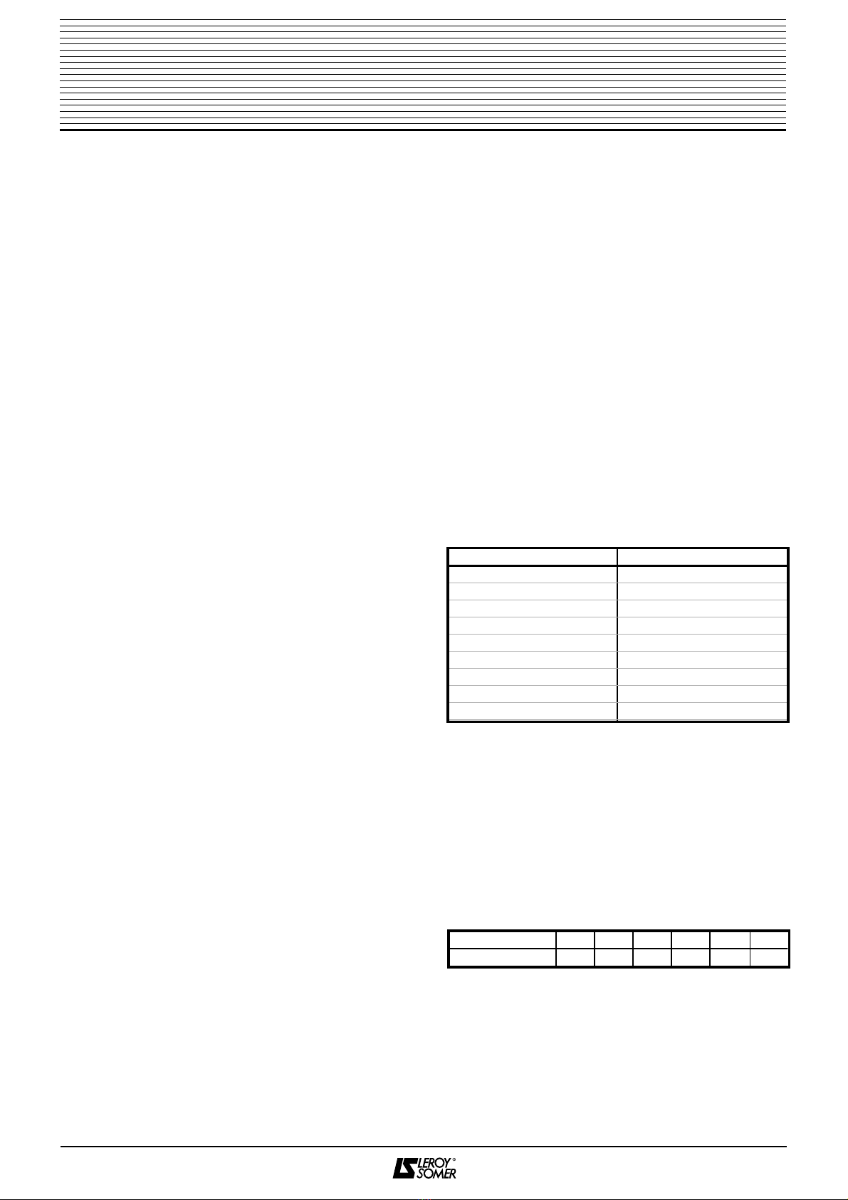
Leroy-Somer Motors recommends the use of Shell Tivela WB oil, a
polyalkylene glycol synthetic lubricant with ISO VG 220 viscosity, which
has been approved by its Technical Department. This lubricant can only
be substituted by the following lubricants with the same class of viscosity
(ISO VG 220) and of the same type (synthetic polyalkylene glycol).
These lubricants have not been approved by LSM, and the user or
recommending retailer is responsible for their use.
CAUTION:
These specifications, instructions and descriptions concern
standard operation. They do not take account of non-standard
versions or special adaptations. If these recommendations are not
adhered to, the gearbox or geared motor may suffer premature
deterioration and the guarantee may be invalidated.
4 - 2 Draining:
In order to reduce pollution which might harm the bearings and seals,
it is important to first drain the oil after a maximum of 1000 hrs of
operation (see "comissioning and running-in"). The drainage interval
depends on the service conditions. If Shell Tivela WB oil is used, we
recommend the following intervals between oil changes :
Drainage can be carried out by use of gravity, removing the 255 plug
situated at the lowest point and/or by inserting a pump into the port on top
of the gearbox. The lubricant should still be warm (for better drainage of
particles in suspension).
Geared motor
Multibloc 3901 - TSA 50
2
SUPPLIER REFERENCE
BP ENERGOL SG-XP
CASTROL ALPHA PG
ICI TRIBOL TRIBOL 800
ICI TRIBOL TRIBOL 1310
KLUBER SYNTHESO HT
LUBRILOG LUBRILOG LY PG
MOBIL GLYGOYLE 30
TEXACO SYNLUBE CLP
TOTAL CORTUSA SY
Output power (kW) 22 18,5 15 11 9 7
Drainage interval (hrs) 7 300 7 300 8 000 9 000 10 000 10 000


