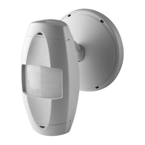
Leviton Mfg. Co., Inc. Lighting & Energy Solutions
20497 SW Teton Avenue, Portland, OR 97062 1-800-736-6682 Tech Line: 1-800-959-6004 Fax: 503-404-5594 www.leviton.com/les
© 2011 Leviton Manufacturing Co., Inc. All rights reserved. Subject to change without notice.
Occupancy Sensor Configuration
COMMON CUSTOMER CONCERNS
1. Sensor not turning the lights on when I walk in the room
a. Auto-ON mode + correct configuration = lights will turn ON within two steps of entry.
b. Adjust location/rotation or angle of the sensor to better cover the entry points.
c. If (b.) has not corrected, then increase PIR (red dial) slightly until desired reaction at entry.
2. Lights are turning off on me = false-OFF
a. Adjust location/rotation or angle of the sensor to better cover the user’s location.
b. If (a.) has not corrected, then increase time delay (black dial) = improves probability of sensing motion.
c. If (a.) and (b.) have not corrected, then increase U/S (green dial) slightly until desired reaction at user
location.
3. Lights are on when no one is in the room = false-on
a. Adjust location/rotation or angle of the sensor to block or remove the offending object (such that
the sensor cannot detect this unwanted motion: minimum 6 feet from air vents and 4 feet from fixtures).
b. PIR will turn the lights ON with any heated motion (oscillating fans, moving parts, pets, etc.).
i. If (a.) has not corrected, then decrease PIR (red dial) slightly until lights turn off (no longer
detecting unwanted motion).
c. U/S will keep the lights ON with any room disturbance (high air flow, flag or cloth blowing, fans, etc.).
i. If (a.) and (b.) have not corrected, then reduce U/S (green dial) slightly until lights turn OFF after
appropriate time setting.
4. Lights turn on in a room when someone walks past in the hallway
a. Auto-ON mode + correct configuration = lights will turn ON within two steps of entry.
b. Adjust location/rotation or angle of the sensor so that you cannot see it from the hallway.
c. If (b). has not corrected, then decrease PIR (red dial) slightly until hallway motion does not activate.
SWITCH FUNCTIONS
Bank A OFF ON
Single/Multi-Tech Mode Multi-Tech Single Tech
PIR/Ultrasonic Mode PIR Ultrasonic
Manual Mode A uto Adapting Enabled A uto Adapting Disabled
Walk-Through Disable Walk-Through Enable Walk-Through Disable
Bank B
Override to ON Auto Mode Lights Forced ON
Override to OFF Auto Mode Lights Forced OFF
Test ModeOFF ON OFF = Enter/Exit Test Mode
LEDs Disable LEDs Enabled LEDs Disable
TABLE 2: SWITCH SETTINGS
SWITCH SETTINGS
SWITCH
A1
A2*
A3
A4
B1
B2
B3
B4
TABLE 1: ADJUSTMENT KNOB SETTINGS
Knob
ColorFunction
Sets the ultrasonic range
Delayed- O Time
Ambient Light Override
(Gray wire only)
Knob Setting
Range setting
Full CCW = min. (OFF)
Full CW = max.
Range setting
Full CCW = min. (OFF)
Full CW = max.
Full CCW = min. (30 sec.)
Full CW = max. (30 min.)
Factory Default
Setting
50%
100%
Full CCW – Lights stay OFF
Full CW – Lightsalways turn ON
(NO ambient light override)
Range – 100-3000 LUX
50%
(10 min)
Blue
Black
SWITCH FUNCTIONS
Bank A OFF ON
Single/Multi-Tech Mode Multi-Tech Single Tech
PIR/Ultrasonic Mode PIR Ultrasonic
Manual Mode A uto Adapting Enabled A uto Adapting Disabled
Walk-Through Disable Walk-Through Enable Walk-Through Disable
Bank B
Override to ON Auto Mode Lights Forced ON
Override to OFF Auto Mode Lights Forced OFF
Test ModeOFF ON OFF = Enter/Exit Test Mode
LEDs Disable LEDs Enabled LEDs Disable
TABLE 2: SWITCH SETTINGS
SWITCH SETTINGS
SWITCH
A1
A2*
A3
A4
B1
B2
B3
B4
TABLE 1: ADJUSTMENT KNOB SETTINGS
Knob
ColorFunction
Sets the ultrasonic range
Sets the infrared range
Ambient Light Override
(Gray wire only)
Knob Setting
Range setting
Full CCW = min. (OFF)
Full CW = max.
Range setting
Full CCW = min. (OFF)
Full CW = max.
Full CCW = min. (30 sec.)
Full CW = max. (30 min.)
Factory Default
Setting
75%
50%
100%
Full CCW – Lights stay OFF
Full CW – Lightsalways turn ON
(NO ambient light override)
Range – 100-3000 LUX
SWITCH FUNCTIONS
Bank A OFF ON
Single/Multi-Tech Mode Multi-Tech Single Tech
PIR/Ultrasonic Mode PIR Ultrasonic
Manual Mode A uto Adapting Enabled A uto Adapting Disabled
Walk-Through Disable Walk-Through Enable Walk-Through Disable
Bank B
Override to ON Auto Mode Lights Forced ON
Override to OFF Auto Mode Lights Forced OFF
Test ModeOFF ON OFF = Enter/Exit Test Mode
LEDs Disable LEDs Enabled LEDs Disable
TABLE 2: SWITCH SETTINGS
SWITCH SETTINGS
SWITCH
A1
A2*
A3
A4
B1
B2
B3
B4
TABLE 1: ADJUSTMENT KNOB SETTINGS
Knob
ColorFunction
Sets the ultrasonic range
Sets the infrared range
Delayed- O Time
Ambient Light Override
(Gray wire only)
Knob Setting
Range setting
Full CCW = min. (OFF)
Full CW = max.
Range setting
Full CCW = min. (OFF)
Full CW = max.
Full CCW = min. (30 sec.)
Full CW = max. (30 min.)
Factory Default
Setting
75%
100%
Full CCW – Lights stay OFF
Full CW – Lightsalways turn ON
(NO ambient light override)
Range – 100-3000 LUX
50%
(10 min)
Blue
Black
Red
SWITCH FUNCTIONS
Bank A OFF ON
Single/Multi-Tech Mode Multi-Tech Single Tech
PIR/Ultrasonic Mode PIR Ultrasonic
Manual Mode A uto Adapting Enabled A uto Adapting Disabled
Walk-Through Disable Walk-Through Enable Walk-Through Disable
Bank B
Override to ON Auto Mode Lights Forced ON
Override to OFF Auto Mode Lights Forced OFF
Test ModeOFF ON OFF = Enter/Exit Test Mode
LEDs Disable LEDs Enabled LEDs Disable
TABLE 2: SWITCH SETTINGS
SWITCH SETTINGS
SWITCH
A1
A2*
A3
A4
B1
B2
B3
B4
TABLE 1: ADJUSTMENT KNOB SETTINGS
Knob
ColorFunction
Sets the ultrasonic range
Delayed- O Time
Ambient Light Override
(Gray wire only)
Knob Setting
Range setting
Full CCW = min. (OFF)
Full CW = max.
Range setting
Full CCW = min. (OFF)
Full CW = max.
Full CCW = min. (30 sec.)
Full CW = max. (30 min.)
Factory Default
Setting
50%
100%
Full CCW – Lights stay OFF
Full CW – Lightsalways turn ON
(NO ambient light override)
Range – 100-3000 LUX
50%
(10 min)
Blue
Black
SWITCH FUNCTIONS
Bank A OFF ON
Single/Multi-Tech Mode Multi-Tech Single Tech
PIR/Ultrasonic Mode PIR Ultrasonic
Manual Mode A uto Adapting Enabled A uto Adapting Disabled
Walk-Through Disable Walk-Through Enable Walk-Through Disable
Bank B
Override to ON Auto Mode Lights Forced ON
Override to OFF Auto Mode Lights Forced OFF
Test ModeOFF ON OFF = Enter/Exit Test Mode
LEDs Disable LEDs Enabled LEDs Disable
TABLE 2: SWITCH SETTINGS
SWITCH SETTINGS
SWITCH
A1
A2*
A3
A4
B1
B2
B3
B4
TABLE 1: ADJUSTMENT KNOB SETTINGS
Knob
ColorFunction
Sets the ultrasonic range
Sets the infrared range
Delayed- O Time
Ambient Light Override
(Gray wire only)
Knob Setting
Range setting
Full CCW = min. (OFF)
Full CW = max.
Range setting
Full CCW = min. (OFF)
Full CW = max.
Full CCW = min. (30 sec.)
Full CW = max. (30 min.)
Factory Default
Setting
75%
100%
Full CCW – Lights stay OFF
Full CW – Lightsalways turn ON
(NO ambient light override)
Range – 100-3000 LUX
50%
(10 min)
Blue
Black
Red
SWITCH FUNCTIONS
Bank A OFF ON
Single/Multi-Tech Mode Multi-Tech Single Tech
PIR/Ultrasonic Mode PIR Ultrasonic
Manual Mode A uto Adapting Enabled A uto Adapting Disabled
Walk-Through Disable Walk-Through Enable Walk-Through Disable
Bank B
Override to ON Auto Mode Lights Forced ON
Override to OFF Auto Mode Lights Forced OFF
Test ModeOFF ON OFF = Enter/Exit Test Mode
LEDs Disable LEDs Enabled LEDs Disable
TABLE 2: SWITCH SETTINGS
SWITCH SETTINGS
SWITCH
A1
A2*
A3
A4
B1
B2
B3
B4
TABLE 1: ADJUSTMENT KNOB SETTINGS
Knob
ColorFunction
Sets the ultrasonic range
Delayed- O Time
Ambient Light Override
(Gray wire only)
Knob Setting
Range setting
Full CCW = min. (OFF)
Full CW = max.
Range setting
Full CCW = min. (OFF)
Full CW = max.
Full CCW = min. (30 sec.)
Full CW = max. (30 min.)
Factory Default
Setting
50%
100%
Full CCW – Lights stay OFF
Full CW – Lightsalways turn ON
(NO ambient light override)
Range – 100-3000 LUX
50%
(10 min)
Blue
Black
ADVANCED OPERATIONS
1. Maximize energy savings with Auto Adapting Technology
(factory default settings).
DIP SWITCH SETTINGS
SWITCH FUNCTIONSSWITCH SWITCH SETTINGS
BANK A OFF ON
A1 N/A Multi-Tech Single Tech
A2 N/A PIR Ultrasonic
A3 Manual Mode Auto Adapting Enabled Auto Adapting Disabled
A4 Walk-Thru Disable Walk-Thru Enabled Walk-Thru Enabled
BANK B
B1 Override to On Auto Mode Lights forced ON
B2 Override to Off Auto Mode Lights forced OFF
B3 Test Mode OFF’ON’OFF Enter/Exit Test Mode
B4 LED Disable LEDs Enabled LEDs Disabled
2. For fixed (stable) settings, the Auto Adapting
and Walk-Thru feature must be disabled.
• Not desirable for maximizing energy
savings.
• Desirable in educational environments
due to vacation periods.
• Desirable if end user expectations are
that all lights will operate ON/OFF the
same way all the time.
• Desirable if troubleshooting, this will
eliminate strange time delays and U/S
sensitivity.
TO DISABLE ADVANCED FEATURES
a. To disable Auto Adapting, flip the A3
dip switch to the rght (ON Position).
b. To disable Walk-Thru, flip the A4 dip
switch to the right (ON Position).
SWITCH FUNCTIONS
Bank A OFF ON
Single/Multi-Tech Mode Multi-Tech Single Tech
PIR/Ultrasonic Mode PIR Ultrasonic
Manual Mode A uto Adapting Enabled A uto Adapting Disabled
Walk-Through Disable Walk-Through Enable Walk-Through Disable
Bank B
Override to ON Auto Mode Lights Forced ON
Override to OFF Auto Mode Lights Forced OFF
Test ModeOFF ON OFF = Enter/Exit Test Mode
LEDs Disable LEDs Enabled LEDs Disable
TABLE 2: SWITCH SETTINGS
SWITCH SETTINGS
SWITCH
A1
A2*
A3
A4
B1
B2
B3
B4
TABLE 1: ADJUSTMENT KNOB SETTINGS
Knob
ColorFunction
Sets the ultrasonic range
Sets the infrared range
Delayed- O Time
Ambient Light Override
(Gray wire only)
Knob Setting
Range setting
Full CCW = min. (OFF)
Full CW = max.
Range setting
Full CCW = min. (OFF)
Full CW = max.
Full CCW = min. (30 sec.)
Full CW = max. (30 min.)
Factory Default
Setting
75%
50%
100%
Full CCW – Lights stay OFF
Full CW – Lightsalways turn ON
(NO ambient light override)
Range – 100-3000 LUX
50%
(10 min)
Blue
Black
Red
Green
Symbol
.
