WARNINGS AND CAUTIONS:
• TO AVOID FIRE, SHOCK, OR DEATH;TURN OFF POWER AT CIRCUIT BREAKER OR FUSE AND TEST THAT THE POWER IS OFF BEFORE WIRING!
• Tobeinstalledand/orusedinaccordancewithelectricalcodesandregulations.
• Ifyouarenotsureaboutanypartoftheseinstructions,consultanelectrician.
• DO NOTcontrolaloadinexcessofthespeciedratings.Damagetotheunit,re,electricshock,personalinjuryordeathcanoccur.
Checkyourloadratingstodeterminesuitabilityforyourapplication.
WARNINGS AND CAUTIONS:
• Use only with LevLok module MSPSW-XST (Stranded wire) or MSPSW-XSD (Solid wire)
• MDS10-IDxisadigitaldevicewithelectroniccomponents,donotterminateLevLokmoduletodevicewithpoweron.
• Donotinstallthisunittocontrolareceptacle.
• Donottouchthesurfaceofthelens.Cleanoutersurfacewithadampclothonly.
• TheCat.No.MDS10-IDxoccupancysensorisintendedtoreplaceastandardlightswitch.
• UsethisdeviceONLY WITH COPPER OR COPPER CLAD WIRE.
SinglePole(OneLocation)orMulti-Location
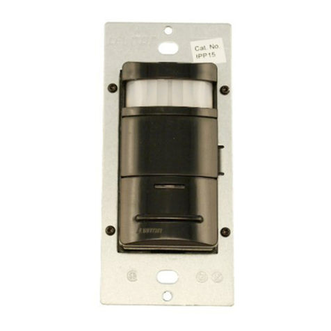
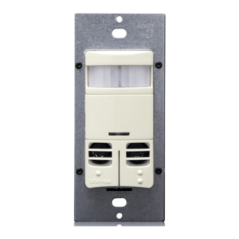
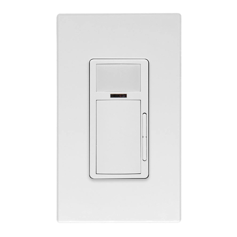
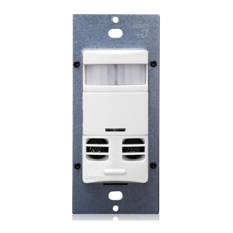
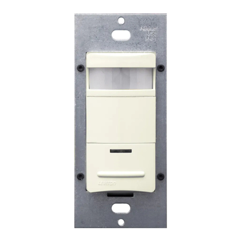
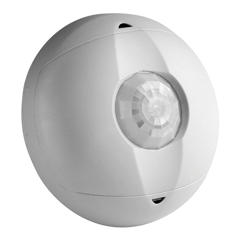
Designer Wall Switch Occupancy Sensor with LevLok
Cat. No. MDS10-IDx
Incandescent - 800W-6.67A@120V-Fluorescent -1200VA-10A@120V-Fluorescent -2700VA-10A@277V-Supplemental - 1/4hp-5.8A@120V
No Minimum Load Required
Compatiblewithelectronicandmagneticballasts,electronicandmagneticlow-voltageballasts,incandescentlamps,andfans.
INSTALLATION INSTRUCTIONS
TOOLS NEEDED TO INSTALL YOUR SENSOR
Slotted/PhillipsScrewdriver ElectricalTape Pliers
Cutters SmallSlottedScrewdriver
LevitonCat.No.MDS10-IDx,DesignerWallSwitchOccupancy
Sensor,isdesignedtodetectmotionfromaheat-emittingsource
(suchasapersonenteringaroom)withinitseld-of-view(monitored
space)andautomaticallyswitchlightsONandOFF.Thecontrolled
lightswillremainONuntilnomotionisdetectedandthescheduled
time-delayhasexpired.
Cat. No. MDS10-IDx is UL listed, CSA certified and conforms to
California Title 24 requirements.
TheOccupancySensorsensesmotionwithinitscoverageareaof
2100sq.ft(195.1m2)maximumandcontrolstheconnectedlighting.
Thisisaself-containeddevicewhichprovidessensingandlight
control.TheOccupancySensorwillturnthelightsONwhenmotion
isinitiallydetected,andkeepthelightsONforaslongasmotionis
detected.
TheOccupancySensorusesasmallsemiconductorheatdetectorthat
residesbehindamulti-zoneopticallens.ThisFresnellensestablishes
dozensofzonesofdetection.Thesensorissensitivetotheheat
emittedbythehumanbody.Inordertotriggerthesensor,thesource
ofheatmustmovefromonezoneofdetectiontoanother.Thedevice
ismosteffectiveinsensingmotionacrossitseld-of-view,andless
effectivesensingmotiontowardsorawayfromitseld-of-view(refer
to Field-of-View diagrams).Keepthisinmindwhenselectingthe
installationlocation(refer to Field-of-View diagrams).
Notethatoccupancysensorsrespondtorapidchangesin
temperature,socareshouldbetakennottomountthedevice
nearaclimatecontrolsource(i.e.radiators,airexchanges,andair
conditioners).Hotorcolddraftswilllooklikebodymotiontothedevice
andwilltriggeritiftheunitismountedtooclose.It is recommended
to mount the Occupancy Sensor at least 6 ft. away from then
climate control source.Thedevicecanbemountedinasinglegang
wallbox.
Inaddition,itisalsorecommendedNOTtomounttheOccupancy
Sensordirectlyunderalargelightsource.Largewattagebulbs
(greaterthan100Wincandescent)giveoffalotofheatandswitching
thebulbcausesatemperaturechangethatcanbedetectedbythe
device.MounttheOccupancySensoratleast6ft.awayfromlarge
bulbs.Ifitnecessarytomountthedevicecloser,lowerthewattageof
thebulbdirectlyoverhead
WARNING:TO AVOID FIRE, SHOCK, OR DEATH; TURN
OFF POWER atcircuitbreakerorfuseandtestthatpoweris
offbeforewiring!
Step 1
ONOFF
ONOFF
ONOFF
ONOFF
ONOFF
ONOFF
ONOFFONOFF
ONOFF
ONOFF
ONOFF
ONOFF
• Pulloffpre-cutinsulationfromsensorleads.
• Makesurethattheendsofthewiresfromthewallboxarestraight
(cut if necessary).
• Removeinsulationfromeachwireinthewallboxasshown.
Preparing and connecting wires:
9/16"
(1.4 cm)
Strip Gage
(measure bare
wire here)
Cut
(if necessary)
Step 3
INSTALLING YOUR SENSOR
NOTE:UsecheckboxeswhenStepsarecompleted.
Installing your Sensor – Single-Pole Application:
Step 4
Identifying your wiring application
(most common):
Step 2
WIRING SENSOR:
Connect wires per WIRING DIAGRAM as follows:Screwwireconnector
onclockwisemakingsuretherearenobareconductorsbelowthewire
connectors.Secureeachconnectorwithelectricaltape.
• GreenorbarecopperwireinwallboxtoGreenlead.
• LineHotwallboxwiretoBlacklead.
• LoadwallboxwiretoBluelead.
NOTE: Allow 1 minute for warm-up after connecting and energizing.
WIRING SENSOR 1:
Connect wires per WIRING DIAGRAM as follows:
• GreenorbarecopperwireinwallboxtoSensor1Greenlead.
• LineHot(common)wallboxwireidentied(tagged)whenremovingold
switchandFirsttravelerfromSensor2toSensor1Blacklead.
• SecondTravelerwallboxwirefromSensor2toSensor1Bluelead.
WIRING SENSOR 2:
Connect wires per WIRING DIAGRAM as follows:
• GreenorbarecopperwireinwallboxtoSensor2Greenlead.
• Loadwallboxwireidentied(tagged)whenremovingoldswitchand
SecondTravelerfromSensor1toSensor2Bluelead.
• FirstTravelerLineHotfromSensor1toSensor2Blacklead.
NOTE: Allow 1 minute for warm-up after connecting and energizing.
NOTE: Use only with LevLok module MSPSW-XST (Stranded wire)
or MSPSW-XSD (Solid wire).
NOTE: TheCat.No.MDS10-IDxrequiresagroundwiretooperate
properly.Ifthereisnogroundwire,ensureelectricalboxisgroundedand
attachgroundwiretoboxwithascrew.Ifthegroundwireisoatingthis
devicewillnotwork.
NOTE: Use only with LevLok module MSPSW-XST (Stranded wire)
or MSPSW-XSD (Solid wire).
NOTE: TheCat.No.MDS10-IDxrequiresagroundwiretooperate
properly.Ifthereisnogroundwire,ensureelectricalboxisgroundedand
attachgroundwiretoboxwithascrew.Ifthegroundwireisoatingthis
devicewillnotwork.
NOTE:EithersensorcanturnthelightsON.Bothsensorsmusttimeout
toOFForbothmanualbuttonsmustbepressedforthelightstogoOFF.
DESCRIPTION
DI-000-MDS10-02A
• Leviton’sDecora®styledesign
• Switcheselectronicballasts
• LowProle,tamper-resistantlens
• AmbientLightOverride
• LevLokquickconnect
FEATURES
3-Way
1. LineorLoad(Seeimportant*instruction)
2. Ground
3. FirstTraveler–notecolor
4. SecondTraveler–notecolor
Single-Pole
1.Line(Hot)
2.Ground
3.Load
IMPORTANT:For3-Wayapplications,notethatoneofthescrew
terminalsfromtheoldswitchbeingremovedwillusuallybeadifferent
color(Black)orlabeledCommon.Tagthatwirewithelectricaltapeand
identifyasthecommon(LineorLoad)inbothswitchwallboxes.
Step 5 Installing your Sensor – 3-Way Wiring Application:
NOTE:Dresswireswithabendtorelievestresswhenmounting
device.
•
Positionallwirestoprovideroominoutletwallboxfordevice.
• Partiallysecuredeviceusinglongmountingscrewsprovided.
• Restorepoweratcircuitbreakerorfuse.
NOTE:ToavoidPERMANENTDAMAGEtotheunit,becareful
NOTTOOVERTURNthecontrolknobsorleverswhensettingthe
Sensor.Thecontrolscanbeaccessedbyremovingthewallplate
(ifapplicable)andcontrolpanelcover(refer to Control Panel
Diagram).Useasmallstraightbladescrewdrivertoadjustknobs
andandangertoadjusttheblinderlevers.
NOTE: DO NOT pressinonblinderleversoruseexcessiveforce
(refer to Control Panel Diagram).
• AttachtheControlPanelcoverwhenthedesiredsettingsare
complete.
If lights do not turn ON, refer to the TROUBLESHOOTING section.
Testing your Sensor prior to completely
mounting in wall box:
Step 6
Wire Connector
(twist clockwise)
Protective Label
