Cat. No. WSWDR-I0W
Field of View
Frequency / Range
Power Supply
Light Required to Sustain
Operation
Charge Time for Full Charge
Environmental
Charge Time before Linking
Radio Certification
50 lux for 30 transmissions per hour
100 lux for 60 transmissions per hour
3 Hours @ 200 lux (after startup)
6 Hours @ 200 lux (cold Start)
Wide Angle = 2000 sq. feet
Long Range = 1600 sq. feet
315 MHz / 50-150 feet
Solar Powered, Battery for backup (optional)
Indoor Use Only
14° to 104°F (-10° to 40°C)
20% to 95% relative humidity (non-condensing)
FCC (United States) SZV-EOSW01
I.C. (Canada) 5713A-EOSW01
2 Minutes @ 50 lux
SPECIFICATIONS
Self-powered Wireless Ceiling Mounted Occupancy Sensor
Cat. No. WSC1x-M9N
DI-001-WSC1X-05A
INSTALLATION English
DESCRIPTION:
The ceiling-mounted Occupancy Sensor saves energy and adds convenience by accurately detecting
when an area is occupied or vacant. It is wireless, solar-powered, and uses a passive infrared (PIR)
sensor to detect motion. The occupancy sensor transmits RF signals that control lighting, HVAC and
outlets to manage building energy consumption more efciently.
•
Sends wireless signals to receiving devices whenever motion is detected.
•
Harvests indoor light to power the sensor and wireless communications.
•
Works with other sensors for enhanced occupancy tracking.
•
Built-in tests to conrm operation at installed location.
•
Supplemental battery or alternative power supply options for extreme low-light conditions.
If occupation is detected by the permanently active PIR sensor, a radio telegram indicating the
occupied status will transmit immediately. An internal timer starts to run for 120 seconds. No radio
telegrams will be sent out when the timer is counting down.
After the timer has nished the countdown, the unit will transmit again if occupancy was detected
during the countdown time period. If occupancy is not detected, the unit will transmit a heartbeat signal
- sending the unoccupied status with a random timing of 2 to 12 minutes. There are two buttons which
allow entrance to a “Walk” or “Light-level” test mode. These test modes are for installation purposes
only and will be exited automatically after 3 minutes.
PLANNING:
Take a moment to plan for the sensor’s successful operation and optimal communication with other
system components. Remove the sensor from its packaging and place it under a bright light to provide
the required startup charge. Optional: To quickly ensure the sensor energy storage is fully charged,
insert a CR2032 battery for 5 minutes.
•
Ensure the location provides consistent and adequate light.
•
Locate the sensor on the ceiling between 8 and 10 ft. (2.4 to 3 m) high with an unobstructed view
of the space.
•
Consider the area’s trafc patterns and principal use, for example, walking, lounging or sleeping.
•
Provide a minimum clearance of 4 ft. (1.2 m) away from heat sources, light bulbs, forced air, or
ventilation systems.
•
Consider the construction materials (such as metal) in the space and obstacles that may interfere
with RF signals.
INSTALLATION:
The occupancy sensor can be mounted on most ceilings with the provided screws, or mounted on
dropped ceilings, using the provided wire bracket.
NOTE: It is often easier to link the sensor before it is mounted on the ceiling. Refer to the
"Programing and Activation" section.
1. Decide where you want to install the occupancy sensor.
2. Remove the mounting plate from the sensor.
3. Decide which of the two installation options is appropriate.
A. Screw Mounting Plate to the Ceiling.
i. Hold the mounting plate in place on the ceiling and use a pencil to lightly mark two
small dots for the screw drill points.
ii. Drill two holes with a 3/16" drill bit and insert the anchors. (see gure 1)
III. Insert the rst screw loosely and level the mounting plate.
iv. Insert the second screw then hand-tighten the rst screw.
B. Mount Using the Wire Bracket. (see gures 2 through 6)
i. Remove the ceiling tile where you want to mount the sensor.
ii. Place the mounting plate squarely on the ceiling tile and use the wire to mark
two points for the holes.
iii. Punch two small holes through the ceiling tile at the marked points
iv. Insert the wire bracket through the two holes in the mounting plate. Make sure the ends
are roughly even.
v. Feed the wires through the holes in the ceiling tile.
vi. On the front of the ceiling tile, atten the wire bracket so it is snug against the
mounting plate.
vii. On the back of the ceiling tile, twist the wires together to hold the mounting plate securely.
4. Attach the sensor to the mounting plate. With the 2-button interface facing you, slide the sensor to
the left on the mounting plate until it snaps into place. (see gure 6)
5. Conrm the sensor is properly positioned to detect motion and has sufcient light to operate, see
the Walk Test and Light Test sections.
PROGRAMMING AND ACTIVATION:
Two or more compatible devices can be linked and congured to provide the desired control. There are
two basic types of devices in the system; transmitters and transceivers.
•
Transmit-only: Transmitters are simple energy-harvesting devices that send RF messages to
communicate a condition, level, or state. Transmitters can only be linked to transceivers.
Examples > Self-powered Light Switches, Occupancy Sensors.
•
Transmit & Receive: Transceivers are controlling devices that send as well as receive RF
messages. They also process relevant control logic, and actuate the appropriate outputs
(switching a light on or off for example). Transceivers can be associated with transmitters as well
as other transceivers. A transceiver can have up to 30 devices associated to it.
Examples > Relays, Gateways
The Occupancy Sensor is a Transmit-only Device. To associate the occupancy sensor to a transceiver;
the transceiver must rst be powered, within wireless range, and set to accepts associations.
Next, the desired transmitter, or another transceiver, is triggered to send a special association/
programming message. The awaiting transceiver receives and stores the association permanently so
the devices can interact to provide a variety of intelligent control options.
To associate or disassociate an Occupancy Sensor:
1. Set the desired transceiver to accept an association (refer to that device’s installation guide).
2. Click the Menu button on the side of the sensor once. This sends a associate/disassociate radio
telegram (see gure 7). NOTE: The button interface on the sensor is used for associating and
testing only. The occupancy timer settings are congured on the transceiver to which the sensor is
associated.
Refer to the “Programming and Activation” section of the transceiver/controller installation guides to
complete the linking process.
TESTING:
Before starting a test, ensure the sensor’s energy storage is fully charged by placing it under bright
light (at least 500 lux) for 20 minutes, or insert a battery for 5 minutes.
If a battery is used to charge the sensor for a light test, ensure it is removed to get an accurate light
measurement.
A test mode will stay active for 3 minutes. To exit a test and resume normal operation, press and hold
the Menu button for 5 seconds.
Walk Test
Use the walk test to conrm that motion is within the sensor’s range.
1. Press and hold the Set button for 5 seconds.
- Red LED will blink to conrm that a walk test is active.
2. Move in and out of the sensor‘s range to determine its coverage area.
- Sensor will blink when it detects motion.
3. Make small hand movements just inside the limit of the sensor‘s range to see if the motion
triggers a response.
Light Test
Use the light test to measure real-time light levels and conrm whether the occupancy sensor has
sufcient light.
1. Create a realistic lighting condition (the test measures the real-time light level).
2. Press and hold the Set button for 10 seconds.
- Red & green LEDs will blink to conrm light test is active.
3. Watch the LED blink rate to determine the light strength.
- The highest is 5 blinks which indicates very good light (200 lux or more). 1 blink indicates
minimum light (25 lux).
NOTE: If there is no blink rate, consider relocating the sensor or installing a battery to provide
supplemental power. If the sensor does not have a sufcient charge, it cannot enter the test modes.
No LED light or 1 red blink when the set button is pressed indicates insufcient charge.
INSTALLING SUPPLEMENTAL BATTERY (OPTIONAL):
If light levels are very low where the sensor is installed, auxiliary battery power (CR2032) can be used
to supplement the solar energy harvester.
1. Remove the sensor from the mounting plate.
2. Identify the battery holder on the circuit board.
3. Insert the battery under the clip with the positive pole (+) up and press it in place (see gure 8).
4. Replace cover and remount the sensor on the wall.
TROUBLESHOOTING:
Sensor does not generate a wireless message:
•
Verify the LED blinks when motion is detected during a walk test.
•
Verify the solar cell is charged properly.
Sensor is activated when there is nothing to detect:
•
Verify there is 4 ft. (1.2 m) clearance from heat sources that may disturb sensing.
•
Reduce sensitivity setting by moving the PIR sensitivity switch on the back to low (the left-hand
position).
Linked device does not respond to wireless messages:
•
Check for environment or range issues.
•
Verify the device is linked.
•
Check the transceiver connection and the wiring for errors.
•
Check if appropriate devices are linked according to good system planning.
Explanation of Occupied & Heartbeat Message Data Telegrams:
• Data Byte 3: Super Capacitor Voltage, 0-250 (0-5V)
.
• Data Byte 2: Solar Panel Current, 0-127 microA
.
• Data Byte 1: 0xFF (occupied) or 0x00 (unoccupied)
.
• Data Byte 0: 0x09 (wall sensor) 0x0B (ceiling sensor)
.
WARNINGS AND CAUTIONS:
•
TO BE INSTALLED AND/OR USED IN ACCORDANCE WITH ELECTRICAL CODES AND REGULATIONS.
•
YOU ARE NOT SURE ABOUT ANY PART OF THESE INSTRUCTIONS, CONSULT AN ELECTRICIAN.
• FOR
INDOOR USE ONLY.
EQUIPMENT NEEDED FOR INSTALLATION:
•
Power drill, 3/16” bit
•
Screwdriver
•
Leveling tool
•
Light meter
•
Battery (CR2032) for testing
COMPATIBLE DEVICES:
This product is compatible with LevNet RF
Advanced Wireless Wall Switches only.
Reference the following catalog numbers:
•
WSS10-0UZ
•
WSS10-GUZ
•
WSS10-AUZ
•
WSS10-UAZ
NOTE: This product will not work with LevNet RF
Basic Wireless Wall Switches.
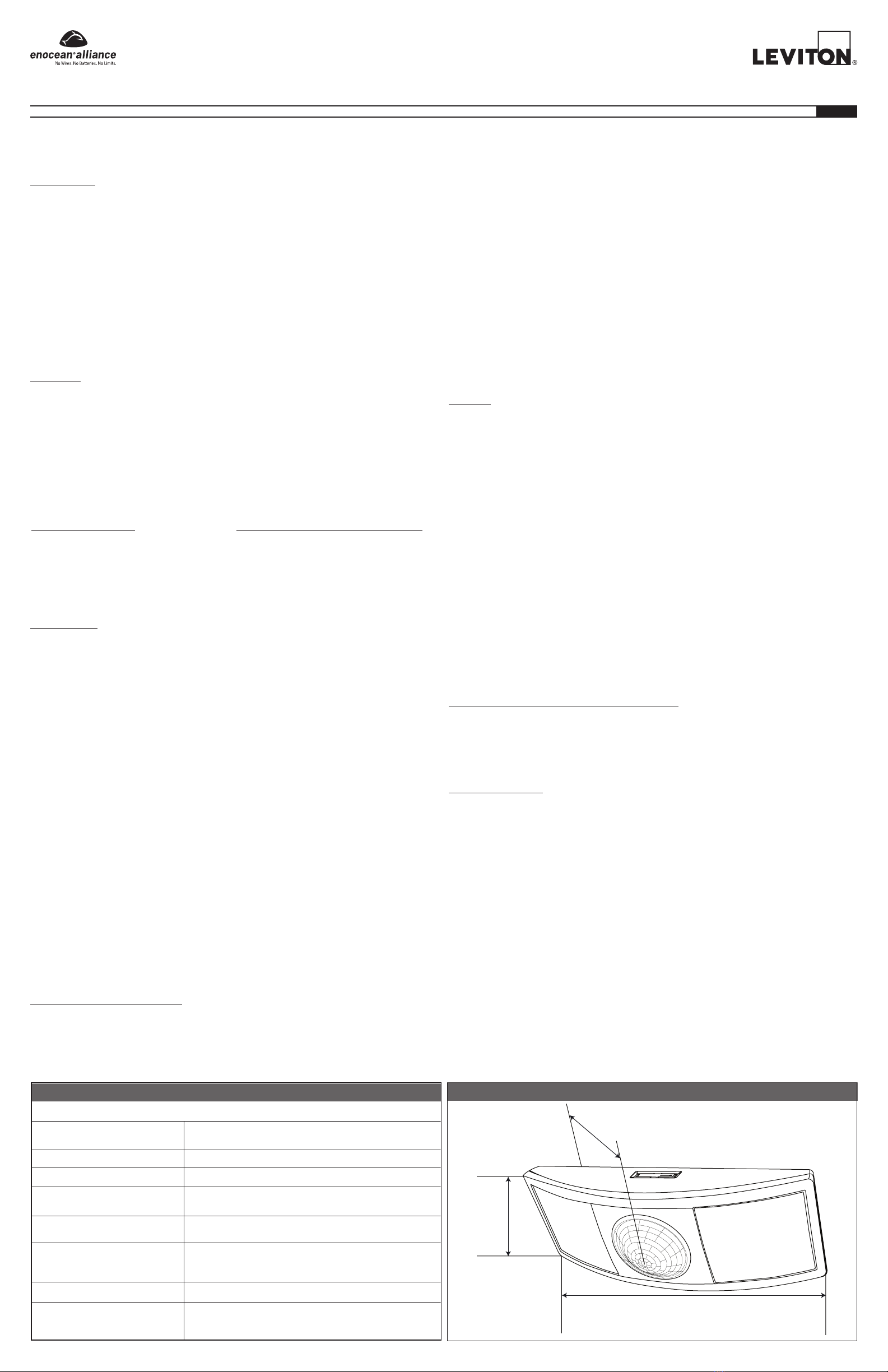
See Field of view below
Solar Cell
Lens
Button Interface
5.8”
(148mm)
1.8” (45.7mm)
1.1” (28mm)2.5” (64mm)
DIMENSIONS
6.3”
159.96mm
1.47”
37.45mm
WSC12-M9NWSC1x-M9N
902 MHz / 50-150 feet
FCC (United States) SZV-STM300U
I.C. (Canada) 5713A-STM300U


