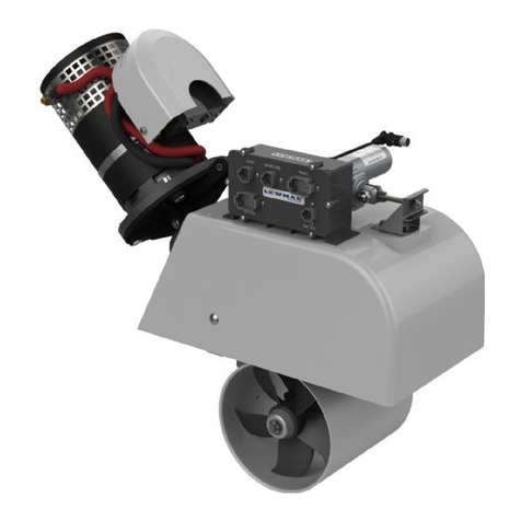
Lewmar 300 SVTAH User manual

300 SVTAH
Installation Manual
Issue B

INDEX
PAGE
INTRODUCTION
CLEANLINESS
CORROSION
RECOMMENDED HYDRAULIC OILS
THRUSTER INSTALLATION
HYDRAULIC INSTALLATION
FLUSHING PROCEDURE
SPEED SENSOR INSTALLATION
OPERATION
MAINTENANCE
CATHODIC PROTECTION SYSTEM
TROUBLE SHOOTING
TECHNICAL DATA
SPARE PARTS
MANUAL RAISE & LOWER OF THRUSTER
THRUSTER DIMENSION DRAWINGS
HYDRAULIC THRUSTER CIRCUIT DRAWINGS
CONTROL PANEL DRAWINGS
WARRANTY
LEWMAR CONTACT DETAILS
3
5
6
7
8
10
11
13
15
17
18
19
21
22
25
27
28
39
43
45

INTRODUCTION
The thrust force created by a Lewmar Bow Thruster will cause a considerable
suction on one side of the vessel and turbulence on the other.
Care should be taken to ensure that there are no swimmers or divers in the
vicinity of the vessel when the Thruster is operated. Also check that there is no
visible floating rope, mooring lines, or timber etc, which could possibly be
ingested into the Thruster potentially damaging the Thruster unit.
The effectiveness of the bow Thruster is largely dependant on the following :
The position of the installation within the hull.
Depth of immersion achieved when fully deployed.
The power source available at the Thruster motor.
The position of the installation within the hull.
The Thruster should be installed as far forward as possible. The centre line of the
hub must be a minimum of 1.5 x propeller diameter below the water line.
Hydraulic power source.
Ensure the correct pipe bore sizes / pressure ratings are installed as per
hydraulic circuit drawing.
Keep the use of bends and elbow fittings to a minimum. Ensure the correct oil
type / grade is used (see separate data sheet ' Recommended Oils ').
The running time of the hydraulic Thruster is typically longer than the electric
version, and is largely dependent on the hydraulic system, tank size etc.
Continuous rating can be achieved with the use of oil coolers, larger oil reservoirs
etc.

INTRODUCTION
Noise considerations.
Because of the considerable power generated by a Lewmar Bow Thruster and
the construction of most vessels there will be noise generated.
It is also possible that the noise level will differ depending on the direction of
thrust. Adhering to the installation instructions stated earlier will reduce the
amount of noise generated.

CLEANLINESS
Contamination in hydraulic systems is the most frequent cause of malfunction or
failure of hydraulic equipment. Depending upon the nature, size and amount of
contamination it can lead to malfunction or serious loss of efficiency and reduced
life of equipment.
Particle contamination can be of metal, rubber, dirt, sand, paint etc. This is more
likely if poor standards of cleanliness are observed when fitting hydraulic hoses
and pipe work or when filling the hydraulic oil tank.
Fluid degradation can cause deposits to form, which clog and impair the smooth
operation of valve spools, etc. This is due to the combined effects of particle,
wear, air entrapment, and excessive temperatures. If strict cleanliness is
observed this condition should not occur.
When installing pipes and fittings, ensure that they are absolutely clean and free
from dirt, scale, and other contaminants. Pipes should be supplied plugged at
either end and these should not be removed until just before the hoses are
installed. Hoses should be blown through with clean compressed air then
installed immediately.
Ensure that the hoses are in good condition, the correct bend radii for the hoses
are observed and that the hoses are of the correct pressure rating
(As specified on the hydraulic drawing).
Threads should be inspected for burrs, which must be removed before hydraulic
hoses are installed. (The use of Teflon, putty, etc for sealing threads must be
avoided). All ports in hydraulic equipment, hoses, pipe work, which is not
immediately connected, should be kept sealed with plugs to prevent the ingress
of dirt.
The hydraulic oil tank should be filled with an ISO 32 grade hydraulic oil which
must be clean and poured through a fine filter to eliminate the possibility of
contamination from the can or from the atmosphere.
Data Sheet : 022

CORROSION
Sea water is both corrosive and conductive, so care should be taken to protect
the underwater components of the Thruster.
Under no circumstances should any equipment be electrically connected to the
Thruster.
The Thruster must not be used as an earth return and it should be noted that
most hydraulic hoses contain wire braid reinforcement and are therefore
conductive. Consequently, the Thruster, hydraulic valves, hydraulic pump and
the prime mover which drives the pump may be inadvertently electrically
connected. For this reason, it should be ascertained that all equipment
connected by the hydraulics hoses have insulated returns or the hoses contain
insulated sections ( eg small lengths of Kevlar reinforced hose ).
It will be necessary to fit sacrificial anodes. Consult a cathodic protection
specialist, follow specialists recommendations on materials, fitting of
anodes and electrical checks. The anodes are usually fitted inside the
propeller shroud and are in strip form. It is vital that they are electrically
bonded to the metal of the Thruster by their fixing bolts. It is the
responsibility of the owner / builder of the boat to ensure that adequate and
effective anodic protection is in place.
The underwater part of the Thruster must be anti - fouled and a primer
compatible with the anti - fouling should be applied first. It is essential that the
primer and the anti - fouling paint is compatible with the Thruster materials.
In the case of a vertically retracting Thruster, it is essential that no paint is
applied to the stainless retracting leg.
Retracting and swing Thrusters should not be left in the " Down " position when
not in use.
The inboard components of the Thruster are normally supplied unpainted, and
these should not be painted. Certain hydraulic components, such as pipe / hose
fittings, and the bodies of some control valves, motors and pumps are made of
mild steel and it is recommended that these are painted after all hydraulic
connections have been finally made and tested.
Data Sheet : 023

RECOMMENDED HYDRAULIC OIL
MANUFACTURER REFERENCE
AGIP OSO 32
ARAL VITAM GF32
VITAM DE32
AVIA AVILUB RSL32
BP ENERGOL HLP32
ENERGOL HLP-D32
CASTROL HYSPIN AWS32
CHEVRON EP HYD. OIL 32
DEFROL HLP22
ESSO NUTO H 32
FINA HYDRAN 32
FUCHS RENOLIN MR10
RENLOIN B10
OPTIMOL HYDRO 5035
MOBIL DTE 24
HYD. OIL HLPD 32
OMV HLP 32
SHELL TELLUS OIL 32
TEXACO RANDO OIL HD A-32
VALVOLINE ETC 25
RECOMMENDED LUBRICATION OIL FOR
THRUSTER HUB.
SHOULD MEET OR EXCEED API GL5
CASTROL EPX 80W / 90
MOBILUBE HD 80W / 90
SHELL SPIRAX HD80W / 90
Data Sheet : 020

THRUSTER INSTALLATION
The 300 SVT is supplied on an aluminium base plate ready for mounting. The
installer is responsible for the watertight integrity of the installation. As a general
rule, the Thruster is installed with the propeller facing to starboard.
When lifting the Thruster unit from its packing case, ensure that adequate lifting
strops are used, and the unit is not lifted by its lead screw assembly or propeller
shroud. When moving the Thruster, ensure that the base plate surfaces are
protected against potential damage.
Once the Thruster seating support has been fabricated and a suitable hole has
been cut in the hull, the Thruster can be installed. Seat the unit down on a thin
gasket of closed cell neoprene or a suitable sealing compound, and bolt down
using M10 bolts.
The 300 SVT Thruster is supplied in the retracted position for ease of
transportation. The Thruster will have to be lowered once located, to have the
hull faring fitted. To lower the Thruster, either energise the raise / lower motor or
by using the mechanical lead screw. To lower mechanically, remove the lead
screw lower locking bolts (M6) from the base plate, and wind the top of the lead
screw with a suitable socket or spanner. Taking care not to damage the limit
switches (Please see Manual Raise & Lower of Thruster).
At the stage of the installation, the raise and lower power is unlikely to be
connected. When raising and lowering the unit, take care not to 'Bottom Out' the
limit switches potentially damaging them.
The lower limit switch is factory set to stop the Thruster just before it hits its
mechanical end stop, and should not be adjusted. However, the upper limit
switch can be set once the hull fairing piece has been fitted to the shroud.
Usually, the hull piece that has been cut out, would be re-used to provide the
Thruster closing plate. This can be glassed using webs, directly onto the
propeller shroud to form a solid structure. If additional bolts are being used,
ensure that the bolt heads do not foul the propeller tips inside the shroud.
A landing or register should be moulded into the hull cut out, to allow the hull
closing piece to 'locate' when the Thruster is fully retracted. This will also
eliminate water flooding the box at high pressure potentially damaging the
gasket / seal when the vessel is pounding at sea.

THRUSTER INSTALLATION
The upper limit switch can be finally set to isolate power to the raise mechanism
as the hull closing plate seats. Ensure that the limit switch actually 'makes' when
the Thruster is fully retracted, otherwise power will be left on the valve / motor
applying unnecessary stress to the shroud / closing plate assembly.
WARNING THE INSTALLATION OF BARS OR GRIDS ACROSS THE TUNNEL
ENTRANCE WILL HAVE A DETRIMENTAL EFFECT ON THRUSTER
PERFORMANCE

INSTALLATION
Hydraulic
Ensure that all pipe sizes / specifications conform to the information supplied on
drawing No 51000099.
Equipment should be accessible to allow for routine maintenance, oil changes
etc. Keep tight bends and hose couplings to a minimum where ever possible.
Where hoses pass through bulkheads or near sharp edges, ensure pipe clamps
or additional shielding of the hose is undertaken to reduce the risk of chaffing.
The hydraulic oil reservoir, valve assembly and return filter all have visual
indictors of oil level and pressure. Please ensure that these gauges are easily
visible once installed.
Hydraulic Electric Circuit
This manual contains 4 different electrical circuits for the 200SVTAH Thruster.
Please refer to the correct drawings for your installation.
•58400170 This circuit is used if you are using a proportional joystick
panel (58400141) and your main engine has a speed trip
fitted.
Refer to Speed Sensor installation details.
•58400174 This circuit is used if you are using a switch control panel
(58400140) or a non proportional joystick panel (58400139)
and your main engine has a speed trip fitted.
Refer to Speed Sensor installation details.
•58400175 This circuit is used if you are using a proportional joystick
panel (58400141).
•58400176 This circuit is used if you are using a switch control panel
(58400140) or a non proportional joystick panel (58400139)
and your main engine has a speed trip fitted.

FLUSHING PROCEDURE GUIDELINES
Flushing of the hydraulic system prior to start up is the single most important
operation of the installation process. Failure to carry out sufficient system
flushing will inevitably lead to rapid wear of components, contamination of valves
and other hydraulic components which in turn may lead to product break down
and failure as well as performance loss.
A few hours spent flushing the system at the installation stage may mean
that many hours or days are not spent later trying to fix a contaminated or
damaged system.
Ideally the system should be flushed using a flushing rig specifically designed to
flush hydraulic systems at the highest pressure and flow as is conveniently
possible. If a flushing rig is not available then the system pump may be used
Prior to flushing
All rigid and flexible pipes, hoses and components should be supplied clean and
capped. The caps should not be removed until they are ready for assembly. If
pipes, hoses or components are not clean, they should be suitably cleaned and
blown through with clean, dry compressed air and capped until ready for use.
Care must be taken when assembling the pipes, hoses and components that no
contamination be allowed into the system.
Flushing Procedure
1 Fill the system with clean fluid through a filter, allow the oil to settle for
half and hour to allow bubbles to disperse. The filter should be of a
rating as specified on the filter component of hydraulic circuit drawing.
2 Before starting the pump ensure that it has been primed and that the
outlet pressure is low.
3 As the system is flushed the level in the reservoir will fall, filling should
continue until the level becomes stable.

FLUSHING PROCEDURE GUIDELINES
4 If possible the system should be flushed as a number of smaller
sections by by - passing parts of the system using other lengths of
tube and suitable adapters. Each section should be flushed for as long
as possible.
a The pipe work should be flushed on its own by by - passing the
valve groups and other components.
b The valve groups should then be connected into the system and
these flushed in turn.
c The pipe work from the valve groups to the functions should be
by - passed and flushed.
d The functions should be connected and flushed last of all. The
functions if possible should be run under no load. If the function
is a bi - directional motor it should be flushed in both directions.
5 The direction of flow should be changed as often as possible, but care
must be taken not to flush equipment out of sequence.
6 All filter condition indicators ( Filter element gauges ) should be
monitored, any filter elements that start to become clogged should be
replaced.
7 Once all flushing has been completed, the whole system should be
checked as a complete system, reservoir oil level checked and filter
elements should be renewed.
Note :- These procedures are only meant as a basic guide to flushing, more
information can be obtained from the British Fluid Power Association.
The British Fluid Power Association ( BFPA )
Cheriton House, Cromwell Business Park
Banbury Road, Chipping Norton
Oxfordshire
OX7 5SR
Tel :- 01608 644114
Fax :- 01608 643738
Publication number :- BFPA A / P9 1992

INSTALLATION INSTRUCTIONS FOR PLC BASED
SPEED SENSORS
Oscillatory sensors are types of proximity detector. A transistor oscillator stops
oscillating when metal objects approach the front of the sensor. This causes a
change to the internal resistance of the sensor, which is detected by the
electronics.
Non-ferrous metals, such as aluminium, brass and copper, may be used as
poles, but measurement gaps are closer than with Ferro-magnetic materials.
The measurement gap can be adjusted using a gauge if there is insufficient
accessibility. In other cases the gap is set by adjusting the sensor until it is in
contact with a stationary pole tooth, then back off by a specific number of turns
as a function of thread pitch. It has been our experience that the optimum gap
will be in the range of 1 to 1.5mm. This gap will correspond to 1 to 1 ½ full turns
on the sensor. Care must be taken to set the sensor at a high point and not a low
point on the pole wheel.
The sensor must be mounted rigid and vibration free, and locked in place by
means of the locking nuts.
Oscillatory sensors are insensitive to electrical interference and it is usually
unnecessary to use a screened connecting cable. Under conditions of extreme
interference re-routing the cable may be required. Total cable length should not
exceed 100 meters.
The correct polarity must be applied to the sensor wires.
The sensor is supplied complete with cables. Markings at cable ends are: -
Brown Lead 1 - Positive
Blue lead - Negative
Black Lead - Signal
Warning
Damage to the sensor will result if the sensor touches the pole wheel while it is in
motion.


OPERATION
If there is a main circuit breaker fitted, ensure the breaker is closed.
Switch on (enable) the system by pressing the main On / Off latching switch
(Green), the switch will then be illuminated.
The system will be live until the On / Off switch is unlatched by re-pressing the
switch or the main power is removed. In the case of the hydraulic Thruster, the
On / Off switch will energise / de-energise the pump clutch and or the control
valve.
If the Thruster is not to be used for a period of time, or the vessel moored, switch
the system off at the main circuit breaker. The Thruster must not be left in the
down position.
WARNING The Thruster must only be run whilst submerged under water,
damage may occur if it is run in free air.
Hydraulic
(PLC Control Version, electric circuits 58400170 & 58400174)
The Thruster is deployed by pressing the down button and raised by pressing the
up button, while the Thruster is in motion, the appropriate button will flash, once
the Thruster is fully up or fully down the appropriate button will stay illuminated.
If both the up and down buttons flash simultaneously, the Thruster is lost (i.e.
neither up nor down), press either the up or down button to correct.
If the On / Off button starts to flash, there is an under / overspeed condition or
there is an low oil condition. Either adjust the speed of the engine or fill the
hydraulic reservoir with hydraulic oil.
The Thruster can only be activated once it is fully deployed. The Thruster is
operated by moving the joystick or pressing the port or starboard buttons.
When changing direction eg from port to starboard, return the joystick to the
centre or release the button and pause for approximately 1 second before
thrusting in the opposite direction. This is to allow the motor to come to a rest
before rotating in the other direction, thus reducing the strain on the Thruster hub
gears.

OPERATION
Hydraulic
(Non PLC Control Version, electric circuits 58400175 & 58400176)
The Thruster is deployed by pressing and holding the down button and raised by
pressing holding the up button, while the Thruster is in motion the button is
extinguished. Once the Thruster is fully deployed or retracted the button will
illuminate.
The Thruster can only be activated once it is fully deployed. The Thruster is
operated by moving the joystick or pressing the port or starboard buttons.
When changing direction eg from port to starboard, return the joystick to the
centre or release the button and pause for approximately 1 second before
thrusting in the opposite direction. This is to allow the motor to come to a rest
before rotating in the other direction, thus reducing the strain on the Thruster hub
gears.

MAINTENANCE
In general very little maintenance of the Thruster is required.
There are two grease nipples which supply grease to the raise / lower
mechanism. One is located on the top plate, and one is on the main Thruster
body. Apply 3 or 4 pumps from a grease gun every four to six months dependant
on the Thruster usage, to ensure trouble free operation.
When applying grease to the Thruster main body grease nipple, first remove the
exit plug located on the opposite side to the grease nipple, this will ensure that no
pressure is generated in the Thruster main body, which would cause the Thruster
to stick. Once sufficient grease has been applied, re-fit the exit plug.
Lightly greasing the lead screw at the same time interval, will enhance operation.
(Hydraulic system)
The hydraulic oil will normally last for many years, but it is advisable to replace
the filter element annually. The filter is fitted with a pressure gauge which
indicates the level of contamination within the element. If the reading starts to
rise above the normal level, it means that the filter element is becoming clogged
and must be replaced. Hydraulic oil will break down over a period of time
irrespective of usage, and therefore should be replaced every two years.
The oil in the gearbox ( hub ) of the unit should be changed annually. There is
both a filler and a drain provided for this purpose. It is important to wrap two or
three turns of PTFE tape around the plugs before refitting them. The plugs have
a tapered thread and therefore care should be taken in order to avoid cross
threading them when refitting. The oil level should be filled to the level of the fill
hole with one of the following oils or an equivalent
( approximately 150 ml ).
CASTROL EPX 80W / 90
MOBILUBE HD 80W / 90
SHELL SPIRAX HD 80W / 90

MAINTENANCE
CATHODIC PROTECTION SYSTEM
When the boat is first commissioned it is important that the anodes are checked
frequently at one month intervals. Check for signs of excessive corrosion. If the
anode has corroded significantly, then renew immediately. If the anodes/unit
shows signs of corrosion shortly after commissioning then it is important that the
vessels electrical system is checked for earth leaks, or other electrical faults that
are possibly accelerating the corrosion process.
(Refer to Corrosion data sheet 023)
Recommended anode inspection plan.
First six (6) months - One (1) month intervals.
Six (6) months to one (1) year - Three (3) month intervals.
One (1) year plus - Six (6) month intervals.
WARNING Anodes are fitted to stop the corrosion of the Thruster hub and
propeller, failure to change the anodes will cause serious damage to your
Thruster

TROUBLE SHOOTING
No Power at Thruster
Check main circuit breaker (if fitted) is on, reset or replace if blown.
Check the control circuit fuses are not blown, replace if necessary. In the above
cases when the On / Off switch is operated the switch will not illuminate.
If power is available to the motor but the propeller will not turn, check the
propeller is not fouled / obstructed with rope or timber etc.
The motor runs, but the propeller is not rotating. Check the shear coupling has
not sheared / slipped caused by ingestion of foreign matter in the tunnel tube.
Replace the shear coupling, by removing the Nyloc propeller nut, and the
propeller. The inner bush will slide from the propeller shaft with the propeller, but
may have separated from the rubber outer. Remove all broken / damaged shear
coupling components and replace. Lightly grease new shear coupling, and press
into existing hub. Taking care not to damage the drive lobes.
Thruster operated with excessive noise / vibration and in once direction the thrust
has noticeably become less powerful.
Propeller damaged due to rope / timer hitting the propeller.
Remove propeller, replace, check that propeller shaft has not been
damaged / bent, check seal.
Sea water in the hub. Check and replace seals as required.
1. No power at Thruster
Check pump drive clutch is engaged, and associated wiring is functional.
Check oil level in hydraulic reservoir, and tank level switch associated
wiring is functional.
Thruster valve plug wiring has correct signals and has good contacts.
2. Loss of power at Thruster
Pump drive clutch slippage, check for ingress of oil or physical damage to
clutch surfaces.
Check pressure gauge reading against specified pressure, and adjust
relief valve to suit.
Valve manual override handle jamming on ships structure.

TROUBLE SHOOTING
3 Raise / Lower system non operative]
Check hydraulic power to the raise / lower motor.
Ensure there is no mechanical obstructions inside or externally restricting
movement.
All SVT Thrusters have a manual override to the raise / lower system
(See Manual Raise / Lower Data Sheet). If the Thruster cannot be
retracted / deployed mechanically, there may be a serious problem
caused by external impact.
Table of contents
Other Lewmar Marine Equipment manuals

Lewmar
Lewmar CPX0- 500W User manual

Lewmar
Lewmar V1/Sport User manual

Lewmar
Lewmar V1 Quick start guide

Lewmar
Lewmar Integra Autopilot Drive User manual

Lewmar
Lewmar 3500 User manual

Lewmar
Lewmar 140 User manual

Lewmar
Lewmar AutoAnchor 550 User manual

Lewmar
Lewmar V8 Quick start guide

Lewmar
Lewmar AA550 User manual

Lewmar
Lewmar AutoAnchor 560 User manual