manuals.online logo
Brands
  1. Home
  2. •
  3. Brands
  4. •
  5. LG
  6. •
  7. Air Conditioner
  8. •
  9. LG AMNH096AP 1 Series User manual

LG AMNH096AP 1 Series User manual

LG
Multi Type Air Conditioner
SERVICE MANUAL
LG
CAUTION
website http://www.lgservice.com
e-mail http://lgservice.com/techsup.html
• BEFORE SERVICING THE UNIT, READ THE SAFETY
PRECAUTIONS IN THIS MANUAL.
• ONLY FOR AUTHORIZED SERVICE PERSONNEL.
MODEL
• Indoor Unit: AMNH076LQL0
AMNH096LQL0
AMNH096LRL0
AMNH126LRL0
AMNH186LTL0
AMNH246LTL0
AMNH096AP*1
AMNH126AP*1
AMNH076DZ*0
AMNH096DU*0
AMNH126DU*0
• Outdoor Unit: A2UW146FA0
A2UW186FA0
A3UW186FA0
A3UW246FA0
A4UW246FA0
A4UW306FA0
A6UW406FA0
A7UW486FA0
A8UW566FA0
Room Type
Art Cool Type
Art Cool Deluxe Type
Duct Type 1 Way CST
AMNH096BTG0
AMNH126BTG0
AMNH186BTG0
AMNH096BPA0
AMNH126BPA0
AMNH186BHA0
AMNH246BHA0
AMNH306BGA0
AMNH366BGA0
AMNH096TCC0
AMNH126TCC0
4 Way CST
AMNH126TEC0
AMNH186TEC0
AMNH246TFC0
AMNH306TFC0
AMNH366TDC0
AMNC126TEC0
AMNC186TEC0
AMNC246TFC0
CVT
AMNH096VEA0
AMNH126VEA0
AMNH186VBA0
AMNH246VBA0
AMNC246VBA0
A2UQ166FA0
A3UQ186FA0
A6UQ406FA0
A8UQ566FA0
2Multi type Air Conditioner
Multi type Air Conditioner Service Manual
TABLE OF CONTENTS
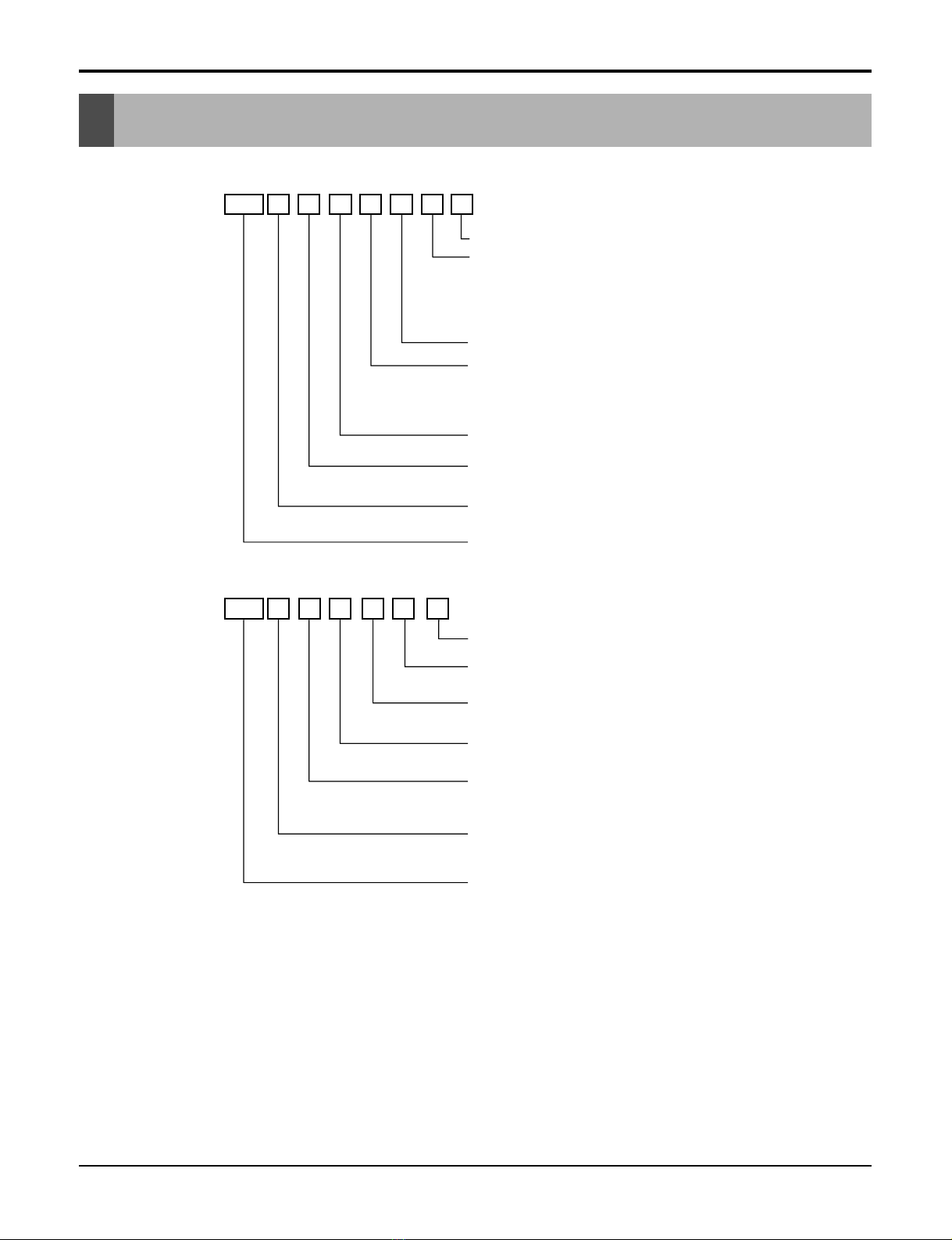
Model Number Nomenclature....................................................................................................................3
Symbols Used in this Manual...................................................................................................................5
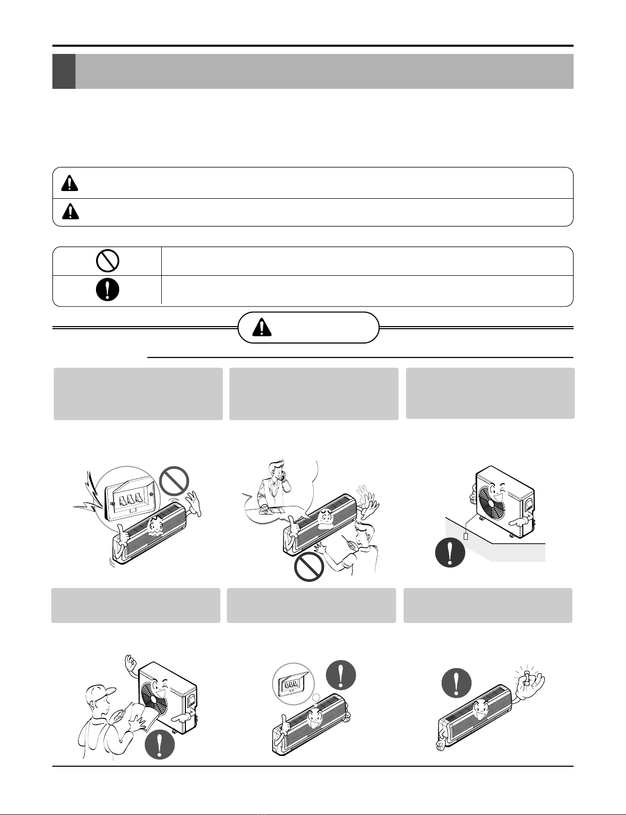
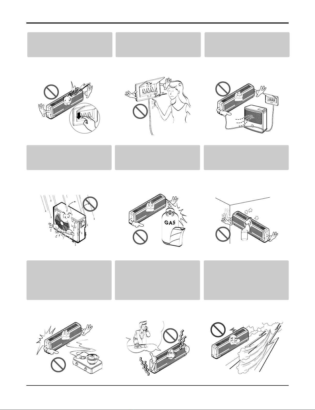
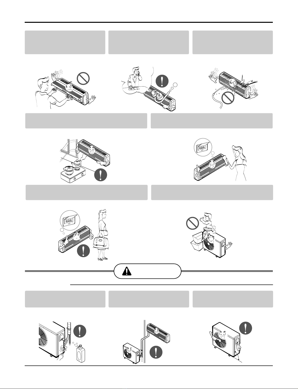
Safety Precautions......................................................................................................................................6
Dimensions................................................................................................................................................12
Indoor Unit.............................................................................................................................................12
Outdoor Unit...........................................................................................................................................20
Product Specifications ............................................................................................................................22
Installation.................................................................................................................................................28
Select the best location of indoor unit ....................................................................................................28
How to fix ...............................................................................................................................................31
Piping and Drainage of Indoor Unit........................................................................................................38
Connection of indoor unit piping.............................................................................................................39
Remote Controller Installation................................................................................................................62
Connecting Pipings and the cable to Outdoor unit.................................................................................64
Checking the Drainage and Pipe forming...............................................................................................66
Maximum Length of Pipe and Extra Charge of Refrigerant Charge.......................................................71
Test Running ..........................................................................................................................................78
System Layout and Piping Length..........................................................................................................81
Installation..............................................................................................................................................82
Installation of The Main Unit...................................................................................................................83
Connection of Piping..............................................................................................................................84
Connection of Wiring..............................................................................................................................85
Operation ..................................................................................................................................................86
Function of control..................................................................................................................................86
Function of Indoor Unit...........................................................................................................................91
Function of Outdoor Unit........................................................................................................................97
Remote Control Operation .....................................................................................................................98
Control Devices and Function ...............................................................................................................106
Simple Central Control.........................................................................................................................106
Term of Each part and Function...........................................................................................................106
Electrical wiring ....................................................................................................................................107
Deluxe Central Control.........................................................................................................................113
Disassembly of the parts (Indoor unit) .................................................................................................119
Indoor unit ............................................................................................................................................119
Schematic Diagram.................................................................................................................................133
Electronic Control Device.....................................................................................................................133
Wiring Diagram.....................................................................................................................................142
Components Locations.........................................................................................................................146
Troubleshooting Guide...........................................................................................................................161
Refrigeration Cycle Diagram................................................................................................................161
Self-diagnosis Function........................................................................................................................166
Cycle Troubleshooting Guide................................................................................................................167
Electronic Parts Troubleshooting Guide ...............................................................................................168
General Information..............................................................................................................................173
(3-way) Valve ...........................................................................................................................................189
Exploded View & Replacement Parts List ............................................................................................193
Indoor Unit ...........................................................................................................................................193
Outdoor Unit ........................................................................................................................................222
Service Manual 3
Model Number Nomenclature
Indoor Unit
Outdoor Unit
AMN H 6
07 QLA0
Serial Number
A2U W 618 F A 0
Electrical Ratings
MPS Inverter Multi System Indoor Unit
Model Type
H : Heat Pump C : Cooling Only
Ex) 7,000 Btu/h '07', 18,000 Btu/h '18'
Nominal Cooling Capacity in Btu/h
Electrical Rating
6 : 1Ø, 220-240V, 50Hz
Chassis Name
Indoor Unit Type
L : Wall Mounted , A : ART COOL
D : ART COOL DELUXE, T : Ceiling Cassette
B : Ceiling Concealed Duct
V : Ceiling & Floor(Convertible)
Function
A : Basic, L : Nano Plasma + Auto Clean(Wall Mounted)
C: Plasma(Ceiling Cassette), G: Low Static Motor
ART COOL(DELUXE) Type Front Panel Color
B : Blue, D : Wood, M : Meta, R : Mirror, W : White
R410A
MPS Inverter Multi
System Outdoor Unit.
And No. of Connectable Indoor Units
Ex) A2U : Connectable max. 2 Indoor Units
A6U : Connectable max. 6 Indoor Units
Model Type
W : DC Inverter Heat Pump Q : DC Inverter Cooling Only.
Ex) 18,000 Btu/h '18', 48,000 Btu/h, '48'
Nominal Cooling Capacity in Btu/h
6 : 1Ø, 220-240V, 50Hz
8 : 3Ø, 380-415V, 50Hz
Multi Type
Function
A : Basic
F : Free Joint Multi Type
Serial Number
Model Number Nomenclature
Panel (Cassette, Built in Duct)
4Multi type Air Conditioner
PT-CFA 3721A10072B 8435002992862 COOLING
TF PT-CFC 3721A10072G 8435002992879 COOLING + PLASMA
PT-HFA 3821A10072A 8435002992886 HEATING
PT-HFC 3721A10072E 8435002992893 HEATING + PLASMA
PT-CCA 3721A10023Z 8435002994095 COOLING
TC PT-CCC 3721A10023W 8435002994101 COOLING + PLASMA
PT-HCA 3721A10023Y 8435002994118 HEATING
CST PANEL PT-HCC 3721A10023V 8435002994125 HEATING + PLASMA
PT-HEA 3721A10105A 8435002992978 HEATING
TE(family look) PT-HEC 3721A10105B 8435002992985 HEATING + PLASMA
PT-CEA 3721A10105C 8435002992954 COOLING
PT-CEC 3721A10105D 8435002992961 COOLING + PLASMA
PT-HAD 3721A10106A 8435002994057 HEATING
TD(family look) PT-HDC 3721A10106B 8435002994064 HEATING + PLASMA
PT-CDA 3721A10106C 8435002994071 COOLING
PT-CDC 3721A10106D 8435002994088 COOLING + PLASMA
BUILT IN DUCT BP PB-HPA 3721A20168A 9K/12K
BQ PB-HQA 3721A20168B 18K/24K
Category CHASSIS PANEL NAME PANEL P/NO. SERIAL NO. Remark
123456
PT-HEA
Basic A
B
Plasma Filter C
D
Elevation Grille E
Elevation Grille + Plasma Filter F
TE/TB/TD Before 2003 : Basic 0
TE/TD Before 2003 : Plasma Filter 1
6. Function
5. Chassis Name
Function
Number Contents
1, 2 Panel for Cassette
3-
4 Cooling/Heatpump
5 Chassis Name
6 Function
Chassis Abbrevation
TC C
TB B
TD D
TE E
TF F
TH H
TJ J
BP P
BQ Q
Service Manual 5
Model Number Nomenclature
Indoor Units
Outdoor Units
2.1
(7000) 2.6
(9000) 3.5
(12000) 5.3
(18000) 7.0
(24000) 8.8
(30000) 10.6
(36000)
SQ AMNH
076LQL0 AMNH
096LQL0 -- - - -
SR -AMNH
096LRL0 AMNH
126LRL0 ----
ST ---
AMNH
186LTL0 AMNH
246LTC0 --
General SP1 -AMNN
096AP*1 AMNN
126AP*1 ----
SZ AMNH
076DZ*0 --- - - -
SU -AMNH
096DU*0 AMNH
126DU*0 ----
1Way TC -AMNH
096TCC0 AMNH
126TCC0 ----
TE --
AMNH/C
126TEC0 AMNH/C
186TEC0 -- -
TF ----
AMNH/C
246TFC0 AMNH
306TFC0 -
TD ---- --
AMNH
366TDC0
BH ---
AMNH
186BHA0 AMNH
246BHA0 --
BG ---- -
AMNH
306BGA0 AMNH
366BGA0
Low
Static BT -AMNH
096BTG0 AMNH
126BTG0 AMNH
186BTG0 -- -
Built in BP -AMNH
096BPA0 AMNH
126BPA0 ----
VE -AMNH
096VEA0 AMNH
126VEA0 ----
VB ---
AMNH
186VBA0 AMNH/C
246VBA0 --
Chasiss
Model Name
Capacity, kW(Btu/h)
Wall
Mounted General
Ceiling &
Floor Convertible
Category Type
ART
COOL Mirror
Ceiling
Cassette 4Way
Ceiling
Concealed
Duct
High
Static
Notes :
A2UW146FA0, A2UW186FA0 and A3UW186FA0 are not TPS inverter system but one inverter compressor system.
MPS Inverter Multi Series Multi Piping Type Distributor Type
Heat Pump Model Name
Rated Capacity Cooling kW(Btu/h)
Heating kW(Btu/h)
Number of Indoor Units to be Connected
Indoor Units kW
Connectable Capacity Btu/h
Power Supply
A2UW146FA0 A2UW186FA0 A3UW186FA0 A3UW246FA0 A4UW246FA0 A4UW306FA0 A6UW406FA0 A7UW486FA0 A8UW566FA0
4.7(1600) 5.3(18000) 5.3(18000) 7.0(24000) 7.0(24000) 8.8(30000) 11.7(40000) 14.0(48000) 16.4(56000)
5.3(1800) 6.3(21600) 6.3(21600) 8.2(28000) 8.2(28000) 10.1(34500) 13.5(46000) 16.2(55200) 18.9(64400)
Max.2 Units Max.2 Units Max.3 Units Max.3 Units Max.4 Units Max.4 Units Max.6 Units Max.7 Units Max.8 Units
2.1~6.2 2.1~7.0 2.1~7.0 2.1~9.7 2.1~9.7 2.1~11.4 4.7~15.2 5.6~18.3 6.6~21.3
7000~21000 7000~24000 7000~24000 7000~33000 7000~33000 7000~39000 16000~52000 19200~62400 22400~72800
1Ø, 220-240V, 50Hz
This symbol alerts you to the risk of electric shock.
This symbol alerts you to hazards that could cause harm to the
air conditioner.
This symbol indicates special notes.
NOTICE
Symbols Used in this Manual
6Multi type Air Conditioner
Safety Precautions
Safety Precautions
To prevent injury to the user or other people and property damage, the following instructions must
be followed.
■Incorrect operation due to ignoring instruction will cause harm or damage. The seriousness is
classified by the following indications.
■Meanings of symbols used in this manual are as shown below.
WARNING
CAUTION
This symbol indicates the possibility of death or serious injury.
This symbol indicates the possibility of injury or damage to properties only.
WARNING
■Installation
Be sure not to do.
Be sure to follow the instruction.
Do not use a defective or under-
rated circuit breaker. Use this
appliance on a dedicated circuit.
•There is risk of fire or electric
shock.
For electrical work, contact the
dealer, seller, a qualified electrician,
or an Authorized Service Center
.
•Do not disassemble or repair the
product. There is risk of fire or
electric shock.
Always ground the product.
•There is risk of fire or electric
shock.
Install the panel and the cover
of control box securely.
•There is risk of fire or electric
shock.
Always install a dedicated cir-
cuit and breaker.
•Improper wiring or installation may
cause fire or electric shock
Use the correctly rated break-
er or fuse.
•There is risk of fire or electric
shock.
Service Manual 7
Safety Precautions
Do not modify or extend the
power cable.
•There is risk of fire or electric
shock.
Do not install, remove, or re-
install the unit by yourself
(customer).
•There is risk of fire, electric shock,
explosion, or injury.
Be cautious when unpacking
and installing the product.
•Sharp edges could cause injury.
Be especially careful of the case
edges and the fins on the con-
denser and evaporator.
For installation, always con-
tact the dealer or an
Authorized Service Center.
•There is risk of fire, electric shock,
explosion, or injury.
Do not install the product on a
defective installation stand.
•It may cause injury, accident, or
damage to the product.
Be sure the installation area
does not deteriorate with age.
•If the base collapses, the air condi-
tioner could fall with it, causing
property damage, product failure,
and personal injury.
Do not let the air conditioner
run for a long time when the
humidity is very high and a
door or a window is left open.
•Moisture may condense and wet or
damage furniture.
Take care to ensure that
power cable could not be
pulled out or damaged during
operation.
•There is risk of fire or electric
shock.
Do not place anything on the
power cable.
•There is risk of fire or electric
shock.
8Multi type Air Conditioner
Safety Precautions
Do not allow water to run into
electric parts.
•It may cause There is risk of fire,
failure of the product, or electric
shock.
Do not store or use flammable
gas or combustibles near the
product.
•There is risk of fire or failure of
product.
Do not use the product in a
tightly closed space for a long
time.
•Oxygen deficiency could occur.
When flammable gas leaks,
turn off the gas and open a
window for ventilation before
turn the product on.
•Do not use the telephone or turn
switches on or off. There is risk of
explosion or fire
If strange sounds, or small or
smoke comes from product.
Turn the breaker off or discon-
nect the power supply cable.
•There is risk of electric shock or
fire.
Stop operation and close the
window in storm or hurricane.
If possible, remove the prod-
uct from the window before
the hurricane arrives.
•There is risk of property damage,
failure of product, or electric shock.
Do not plug or unplug the
power supply plug during
operation.
•There is risk of fire or electric
shock.
Do not touch(operate) the
product with wet hands.
•There is risk of fire or electrical
shock.
Do not place a heater or other
appliances near the power
cable.
•There is risk of fire and electric
shock.
Gasolin
Service Manual 9
Safety Precautions
Do not open the inlet grill of the product
during operation. (Do not touch the elec-
trostatic filter, if the unit is so equipped.)
•There is risk of physical injury,
electric shock, or product failure.
When the product is soaked
(flooded or submerged), contact
an Authorized Service Center.
•There is risk of fire or electric
shock.
Be cautious that water could
not enter the product.
•There is risk of fire, electric shock,
or product damage.
Ventilate the product from time to time when
operating it together with a stove, etc.
•There is risk of fire or electric shock.
Turn the main power off when cleaning or
maintaining the product.
•There is risk of electric shock.
When the product is not be used for a long time, dis-
connect the power supply plug or turn off the breaker.
•There is risk of product damage or failure, or unintend-
ed operation.
Take care to ensure that nobody could step on
or fall onto the outdoor unit.
•This could result in personal injury and product dam-
age.
Always check for gas (refrigerant) leak-
age after installation or repair of product.
•Low refrigerant levels may cause
failure of product.
Install the drain hose to ensure that
water is drained away properly.
•A bad connection may cause water
leakage.
Keep level even when
installing the product.
•To avoid vibration or water leak-
age.
CAUTION
■Installation
90°
10 Multi type Air Conditioner
Do not block the inlet or outlet
of air flow.
•It may cause product failure.
Use a soft cloth to clean. Do
not use harsh detergents, sol-
vents, etc.
•There is risk of fire, electric shock,
or damage to the plastic parts of
the product.
Do not touch the metal parts of
the product when removing the
air filter. They are very sharp!
•There is risk of personal injury.
Safety Precautions
Do not install the product
where the noise or hot air
from the outdoor unit could
damage the neighborhoods.
•It may cause a problem for your
neighbors.
Use two or more people to lift
and transport the product.
•Avoid personal injury.
Do not install the product
where it will be exposed to
sea wind (salt spray) directly.
•It may cause corrosion on the
product. Corrosion, particularly on
the condenser and evaporator fins,
could cause product malfunction or
inefficient operation.
Do not expose the skin directly to cool air for
long periods of time.
(Don't sit in the draft.)
•This could harm to your health.
Do not use the product for special purposes,
such as preserving foods, works of art, etc. It
is a consumer air conditioner, not a precision
refrigeration system.
•There is risk of damage or loss of property.
■Operational
Wax
Thinner
Service Manual 11
Do not step on or put anyting
on the product. (outdoor
units)
•There is risk of personal injury and
failure of product.
Always insert the filter secure-
ly. Clean the filter every two
weeks or more often if neces-
sary.
•A dirty filter reduces the efficiency
of the air conditioner and could
cause product malfunction or dam-
age.
Do not insert hands or other
objects through the air inlet or
outlet while the product is
operated.
•There are sharp and moving parts
that could cause personal injury.
Do not drink the water drained
from the product.
•It is not sanitary and could cause
serious health issues.
Use a firm stool or ladder
when cleaning or maintaining
the product.
•Be careful and avoid personal
injury.
Replace the all batteries in the
remote control with new ones
of the same type. Do not mix
old and new batteries or dif-
ferent types of batteries.
•There is risk of fire or explosion
Do not recharge or disassemble the batteries.
Do not dispose of batteries in a fire.
•They may burn or explode.
If the liquid from the batteries gets onto your
skin or clothes, wash it well with clean water.
Do not use the remote if the batteries have
leaked.
•The chemicals in batteries could cause burns or other
health hazards.
Safety Precautions
12 Multi type Air Conditioner
Dimensions
Dimensions
Indoor Unit
1. Split Type Indoor 2. Art Cool Type Indoor Unit
Installation plate
Right rear piping
Left rear piping
ø70mm ø70mm
50mm
20mm
20mm
80mm
A
A
ø70mm
Center
Center
ø70mm
Left rear piping Right rear piping
A
A
H
W
Tubing hole cover
Left rear piping Right rear piping
Hole Center ø70mm
"D" "C"
(7K, 9K) (9K, 12K) (18K, 24K)
Pipe Hole
Fix Hole
Hanger Hole
H
WD
W mm 824 900 1,080
H mm 260 285 314
D mm 155 156 172
SQ
7K,9K SR
9K, 12K ST
18K, 24K
MODEL
DIM
Service Manual 13
Dimensions
Installation plate
D
H
W
MODEL
DIM Unit
W mm 900 1030
H mm 272 290
D mm 135 153
SZ
7K SU
9K, 12K
3. Art Cool Deluxe Type
14 Multi type Air Conditioner
Dimensions
W
H
D
HH
D
BH/BG
BP BT/BT1
W
WD
MODEL
DIM
W(mm) 708 1060 880 1180 580
H(mm) 230 230 260 298 300
D(mm) 537 357 450 450 750
BT
9K/12K BT1
18K BH
18K/24K BG
30K/36K BP
9K/12K
4. Duct Type
Service Manual 15
Dimensions
5. CVT Type
VE(9K/12K)
VB(18K/24K)
R
Installation plate
D
W
H
250mm
36mm
36mm 1076mm
(Rear Side)
63mm
38mm
175mm
(Installation Plate)
392mm
265mm
468mm
D
WH
MODEL
DIM Unit
W mm 900 1200
H mm 285 615
D mm 156 205
VE
9K/12K VB
18K/24K
16 Multi type Air Conditioner
Dimensions
694.5
1050
480
846
860
328.430.8 390
893.4
931.6
16.7
50
42.7
7
155
97.7
37
116.3
141.8
180
164
194.4
91.6
180
430
130
Ø80
Ø55
180
91.6
1,000 (Ceiling opening)
931.6
893.4 (Hanging bolt)
328.4 (Hanging bolt)
860
390
30.8
430 (Ceiling opening)
4
5
6
32
1
6. CST Type - TC (9K/12K)6. CST Type - TC (9K/12K)
(unit : mm)
Number Name Descripition
1 Liquid pipe connection ø6.35 flare
2 Gas pipe connection ø9.52 flare
3 Drain pipe connection
4 Power supply connection
5 Air discharge grill
6 Air suction grill
Service Manual 17
CLOSE OPEN OPEN CLOSE
269
670
30
570
269
190.5
160
52
90
90
120.4 30 521
670 570
450
40
110 110
670
670
4
1
3
2
5
6
Unit:mm
570 Unit size
570 Unit size
450 (Hanging bolt)
7575
600 (Ceiling opening)
521(Hanging bolt) 39.5
39.5
7. CST Type - TE (12K/18K)
Dimensions
(unit : mm)
Number Name Descripition
1 Liquid pipe connection ø6.35 flare
2 Gas pipe connection
12k: ø9.52, 18k: ø12.7 flare
3 Drain pipe connection
4 Power supply connection
5 Air discharge grill
6 Air suction grill
18 Multi type Air Conditioner
8. CST Type - TF (24K/30K)
292
850
850
850
850
744
658
572
744
292
212
150
54
90
90
192 117
70
110 110
41
3
2
5
6
Unit:mm
744 Unit size
744 Unit size
658 (Hanging bolt)
6666
790 (Ceiling opening)
572(Hanging bolt) 109
109
30
(unit : mm)
Number Name Descripition
1 Liquid pipe connection ø6.35 flare
2 Gas pipe connection
ø12.7 flare-24K, ø15.88 flare-30K
3 Drain pipe connection
4 Power supply connection
5 Air discharge grill
6 Air suction grill
Dimensions
Service Manual 19
9. CST Type - TD(36K)
288
950
950
950
950
290
210.5
180
52
140
40
110
30
90
90
110
55
840
785
840
678
Fresh Air Inlet
Unit:mm
840 Unit size
840 Unit size
672 (Hanging bolt) 101.5101.5
875 (Ceiling opening)
785 (Hanging bolt) 45
45
4
5
6
1
3
2
Dimensions
(unit : mm)
Number Name Descripition
1 Liquid pipe connection ø6.35 flare
2 Gas pipe connection ø15.88 flare
3 Drain pipe connection
4 Power supply connection
5 Air discharge grill
6 Air suction grill
20 Multi type Air Conditioner
Outdoor Unit
W
D
L1
L2
L4 L3
H
L7L5L6
D
W
H
W mm 800 870 870 870 900
H mm 555 655 800 1060 1165
D mm 262 320 320 320 370
L1 mm 340 370 370 360 460
L2 mm 37 25 25 20 45
L3 mm 544 775 775 1040 1135
L4 mm 11 25 25 20 30
L5 mm 590 546 546 550 550
L6 mm 105 160 160 160 175
L7 mm 105 160 160 165 175
16K 14K,18K 24K 30K 40K
MODEL
DIM
30K/40K
14K/16K/18K/24K
Dimensions

This manual suits for next models

47

Other LG Air Conditioner manuals

LG ARND30UDBE4 User manual

LG

LG ARND30UDBE4 User manual

LG LS090HSV4 User manual

LG

LG LS090HSV4 User manual

LG LWHD1807HR User manual

LG

LG LWHD1807HR User manual

LG ARTCOOL LA121CNM User manual

LG

LG ARTCOOL LA121CNM User manual

LG LM50 Operation manual

LG

LG LM50 Operation manual

LG LS-E0960CL User manual

LG

LG LS-E0960CL User manual

LG AR-DR12-05A User manual

LG

LG AR-DR12-05A User manual

LG AP-Z488TC0 User manual

LG

LG AP-Z488TC0 User manual

LG Mega LS180HEV2 User manual

LG

LG Mega LS180HEV2 User manual

LG Convertible & Ceiling suspended Air... User manual

LG

LG Convertible & Ceiling suspended Air... User manual

LG VR182CE NC0 User manual

LG

LG VR182CE NC0 User manual

LG LW1811ER User manual

LG

LG LW1811ER User manual

LG HMC030KD1 User manual

LG

LG HMC030KD1 User manual

LG MU2R15 User manual

LG

LG MU2R15 User manual

LG T186VC User manual

LG

LG T186VC User manual

LG A2UW18GFA0 User manual

LG

LG A2UW18GFA0 User manual

LG JBNQ18GB2A1 User manual

LG

LG JBNQ18GB2A1 User manual

LG Multi V User manual

LG

LG Multi V User manual

LG C09AWM User manual

LG

LG C09AWM User manual

LG ARNU07GSF14 User manual

LG

LG ARNU07GSF14 User manual

LG Central Air Conditioning Remote Condensing... Assembly instructions

LG

LG Central Air Conditioning Remote Condensing... Assembly instructions

LG ARNU24GB4G2 User manual

LG

LG ARNU24GB4G2 User manual

LG MULTI V ARN Series Installation and operation manual

LG

LG MULTI V ARN Series Installation and operation manual

LG AS-W123B4B1 User manual

LG

LG AS-W123B4B1 User manual

Popular Air Conditioner manuals by other brands

Friedrich MR36Y3J owner's manual

Friedrich

Friedrich MR36Y3J owner's manual

Daikin RXM42M3V1B9 installation manual

Daikin

Daikin RXM42M3V1B9 installation manual

Toshiba RAS-18J2KVSG-TR owner's manual

Toshiba

Toshiba RAS-18J2KVSG-TR owner's manual

Gree GWH18TC-S3DNA1D Service manual

Gree

Gree GWH18TC-S3DNA1D Service manual

Trane 4TTL6018A1000A Installation and operation manual

Trane

Trane 4TTL6018A1000A Installation and operation manual

Mitsubishi PEFY-P25 VMS1-E Operation manual

Mitsubishi

Mitsubishi PEFY-P25 VMS1-E Operation manual

Mitsubishi Electric PAC-SG95LE-E installation manual

Mitsubishi Electric

Mitsubishi Electric PAC-SG95LE-E installation manual

GE AZ28E12DAB Dimensions and installation information

GE

GE AZ28E12DAB Dimensions and installation information

Everwell MKTC1213E-16 Service manual

Everwell

Everwell MKTC1213E-16 Service manual

Mitsubishi Electric Mr. Slim MXZ-2B20NA Service manual

Mitsubishi Electric

Mitsubishi Electric Mr. Slim MXZ-2B20NA Service manual

Soleus Air WS2-15E-201 operating instructions

Soleus Air

Soleus Air WS2-15E-201 operating instructions

Carrier MMY-MAP0724FT9UL Service manual

Carrier

Carrier MMY-MAP0724FT9UL Service manual

Sanyo KMS0772 installation instructions

Sanyo

Sanyo KMS0772 installation instructions

Sinclair ASH-13AIA1 PT user manual

Sinclair

Sinclair ASH-13AIA1 PT user manual

Maytag M6P09D2B user guide

Maytag

Maytag M6P09D2B user guide

Toshiba RAS-B10UFV installation manual

Toshiba

Toshiba RAS-B10UFV installation manual

Bard WA4822 installation instructions

Bard

Bard WA4822 installation instructions

Samsung AW07F2SBA Owner's instructions

Samsung

Samsung AW07F2SBA Owner's instructions

manuals.online logo
manuals.online logoBrands
  • About & Mission
  • Contact us
  • Privacy Policy
  • Terms and Conditions

Copyright 2025 Manuals.Online. All Rights Reserved.