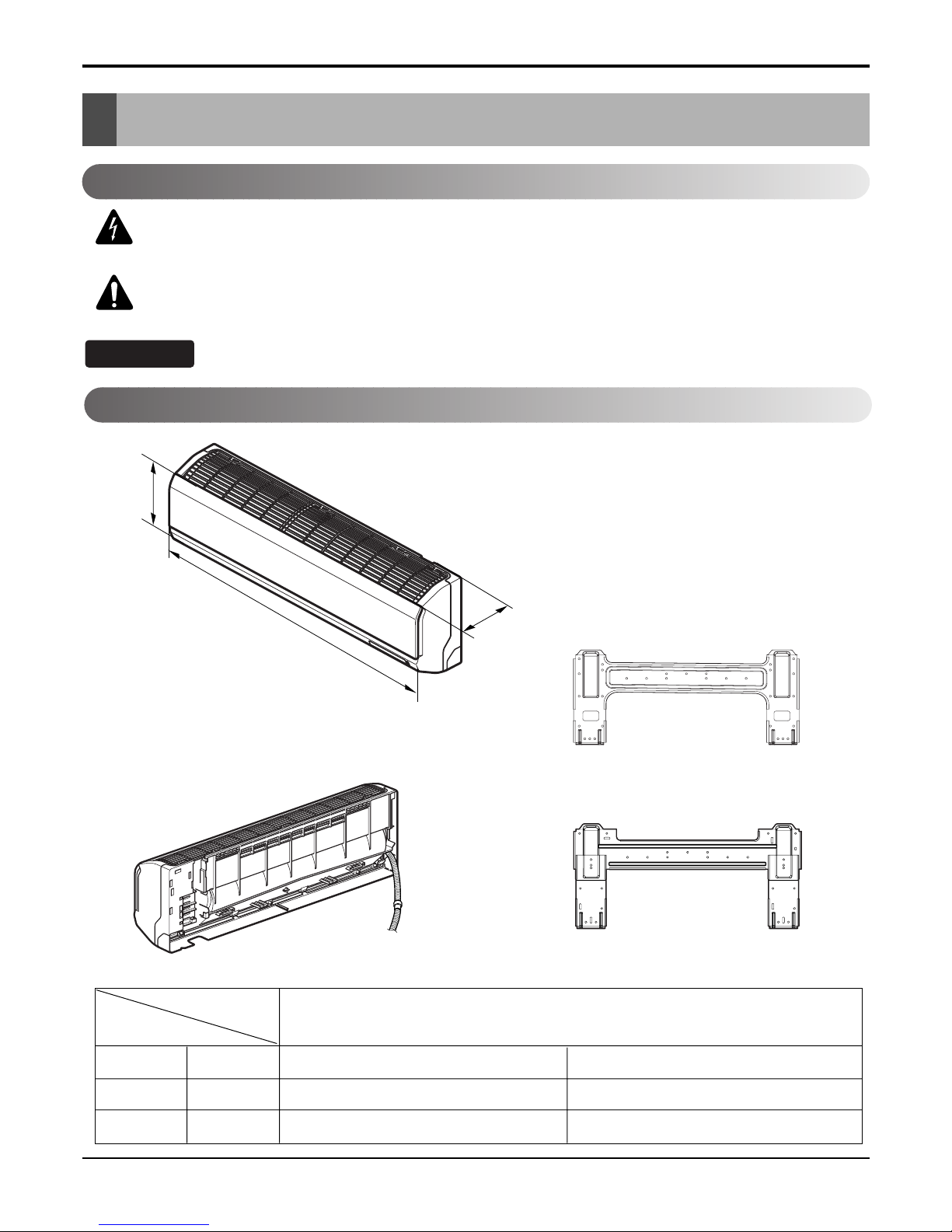
LG AS-W0964DH0/GH0 User manual

Room Air Conditioner
SVC MANUAL(Exploded View)
MODEL : AS-W0964DH0/GH0
AS-W0964DH1
AS-W1264DH0/GH0
AS-W1865DH0
AS-W1224DH0
AS-W1424DH0
AS-W1825DH0
AS-W096E1G0
AS-W126E1G0
CAUTION
Before Servicing the unit, read the safety precautions in General SVC manual.
Only for authorized service personnel.
Internal Use Only
http://biz.lgservice.com

- 2 -
Copyright ©2008 LG Electronics. Inc. All right reserved.
Only for training and service purposes LGE Internal Use Only
Air Conditioner Service Manual
TABLE OF CONTENTS
LG Model Name.................................................................................................................................3
Safety Precautions ...........................................................................................................................5
Dimensions .....................................................................................................................................10
Installation.......................................................................................................................................14
Connecting the cable between indoor unit and outdoor unit.....................................................24
Checking the drainage and forming the pipings .........................................................................26
Air purging ......................................................................................................................................27
Test running ....................................................................................................................................29
Functions.........................................................................................................................................30
Operation.........................................................................................................................................33
Disassembly....................................................................................................................................44
Troubleshooting Guide ..................................................................................................................47
Schematic Diagram ........................................................................................................................67
Product Specifications ..................................................................................................................76
Exploded View ................................................................................................................................80

- 3 -
Copyright ©2008 LG Electronics. Inc. All right reserved.
Only for training and service purposes LGE Internal Use Only
LG Model Name
LG Model Name
2003
12 - 345678910
Code Type Code of Model Meaning
1 Producing Center, A~Z L: Chang-won R22 N: India
Refrigerant A: Chang-won R410A Z: Brazil
C: Chang-won R407C D: Indonesia
T: China M: Mexico
K: Turkey R22 V: Vietnam
E: Turkey R410A S: Out Sourcing
H: Thailand
2 Product Type A~Z S: Split Type Air Conditioner
3 Cooling/Heating/Inverter A~Z C: Cooling only
H: Heat pump
X: C/O + E/Heater
Z: H/P + E/Heater
V: AC Inverter C/O
N: AC Inverter H/P
Q: DC Inverter C/O
W: DC Inverter H/P
4, 5 Capacity 0~9 Cooling/Heating Capacity
Ex. "09" →9,000 Btu/h
6 Electric Range 1~9 1: 115V/60Hz, A: 220V, 50Hz, 3Phase
A~Z 2: 220V/60Hz B: 208~230V, 60Hz, 3Phase
3: 208-230V/60Hz C: 575V, 50Hz, 3Phase
5: 200-220V/50Hz D: 440~460, 60Hz, 3Phase
6: 220-240V/50Hz E: 265V, 60Hz
7: 110V, 50/60Hz F: 200V, 50/60Hz
8: 380-415V/50Hz
9: 380-415V/60Hz
7 Chassis A~Z Name of Chassis of Unit
Ex. 4 →S4 Chassis
8 Look A~Z Look,
Color (Artcool Model)
9 Function A~Z
10 Serial No. 0~9 LG Model De
* ARTCOOL COLOR
velopment Serial No.
Basic A
Basic+4Way B
Plasma Filter C
Plasma Filter+4 Way D
Tele+LCD E
Tele+LCD+Nano plasma+4Way F
Nano Plasma F+(A/changeove)+A/clean+Low A G
Nano Plasma F+(A/changeove)+A/clean+4way+Low A H
Tele+LED+4way I
Internet J
Plasma F+4Way+Oxy generator K
Nano Plasma F+(A/changeove)+A/clean L
Nano Plasma F+(A/changeove)+A/clean+4way M
Nano Plasma F+(A/changeove)+A/clean+PTC N
Nano Plasma F+(A/changeove)+Autoclean+4way+PTC P
Nano Plasma F+(A/changeove)+A/clean+4way+Low A+PTC Q
Negative ION+A/Clean R
(Nano)Plasma+Negative ION+A/Clean S
4way+(Nano)Plasma F+Negative ION+Healthy dehumidification+A/Clean
T
Nano Plasma F+4Way+(A/changeove)+A/clean+ U
R Mirror
W White
B Blue
D Wood
M Metal
C Cherry
N Walnut
A Gogh
S Sisley
Q Quran
K Mecca

- 4 -
Copyright ©2008 LG Electronics. Inc. All right reserved.
Only for training and service purposes LGE Internal Use Only
LG Model Name
2004~
12 - 345678910
Code Type Code of Model Meaning
1 Producing Center, A~Z
L Chang_won R22
A Chang_won R410A
C Chang_won R407C
T China
K Turkey R22
E Turkey R410A
H Thailand
N India
Z Brazil
D Indonesia
X Mexico
V Vietnam
S Out sourcing
Refrigerant
2 Product Type A~Z S: Split Type Air Conditioner
3 Cooling/Heating/Inverter A~Z C: Cooling only
H: Heat pump
X: C/O + E/Heater
Z: H/P + E/Heater
V: AC Inverter C/O
N: AC Inverter H/P
Q: DC Inverter C/O
W: DC Inverter H/P
4, 5 Capacity 0~9 Cooling/Heating Capacity
Ex. "09" →9,000 Btu/h
6 Electric Range 1~9 1: 115V/60Hz, A: 220V, 50Hz, 3Phase
A~Z 2: 220V/60Hz B: 208~230V, 60Hz, 3Phase
3: 208-230V/60Hz C: 575V, 50Hz, 3Phase
5: 200-220V/50Hz D: 440~460, 60Hz, 3Phase
6: 220-240V/50Hz E: 265V, 60Hz
7: 110V, 50/60Hz F: 200V
CHASSIS Look
D
G
1
K
L
G
M
N
D
P
Division
Panel Type(Deluxe)
Grille Type
Panel Type(Deluxe)
Fighting 'Look'
(LG1)
(LG2)-SEMI PANEL
OEM1
OEM2
Panel Type(Deluxe)
LG3
, 50/60Hz
8: 380-415V/50Hz
9: 380-415V/60Hz
7 Chassis A~Z Name of Chassis of Unit
Ex. 4→S4 Chassis
8 Look A~Z Look,
Color (Artcool Model)
9 Function A~Z
10 Serial No. 0~9 LG Model De
* ARTCOOL COLOR
velopment Serial No.
R Mirror
W White
B Blue
D Wood
M Metal
C Cherry
S4/S5/SD
SE
S6
SQ
SR
ST
Basic A
Basic+4Way B
Plasma Filter C
Plasma Filter+4 Way D
Tele+LCD E
Tele+LCD+Nano plasma+4Way F
NBF F+(A/changeove)+A/clean+Low A G
NBF F+(A/changeove)+A/clean+4way+Low A H
Tele+LED+4way I
Internet J
Plasma F+4Way+Oxy generator K
NBF F+(A/changeove)+A/clean L
NBF F+(A/changeove)+A/clean+4way M
NBF F+(A/changeove)+A/clean+PTC N
NBF F+(A/changeove)+Autoclean+4way+PTC P
NBF F+(A/changeove)+A/clean+4way+Low A+PTC Q
(Nano)Plasma+ION+A/Clean S
4way+(Nano)Plasma F+
Negative ION+Healthy dehumidification
+A/Clean T
Nano Plasma F+4Way+(A/changeove)+A/clean+Oxy generator U
4way+(Nano)Plasma F+Negative ION+Healthy dehumidification+A/Clean+Oxy generator
V
Dry contact W
Wire remocon 8

- 5 -
Copyright ©2008 LG Electronics. Inc. All right reserved.
Only for training and service purposes LGE Internal Use Only
Safety Precautions
Safety Precautions
To prevent injury to the user or other people and property damage, the following instructions must
be followed.
■Incorrect operation due to ignoring instruction will cause harm or damage. The seriousness is
classified by the following indications.
■Meanings of symbols used in this manual are as shown below.
This symbol indicates the possibility of death or serious injury.
This symbol indicates the possibility of injury or damage to properties only.
Be sure not to do.
Be sure to follow the instruction.
Do not use damaged power cords, plugs, or a
loose socket.
Always use the power plug and socket with the
ground terminal.
• There is risk of fire of electric shock. • There is risk of electric shock.
Install the panel and the cover of control box
securely.
Do not modify or extend the power cord.
• There is risk of fire of electric shock. • No grounding may cause electric shock.
■Installation

- 6 -
Copyright ©2008 LG Electronics. Inc. All right reserved.
Only for training and service purposes LGE Internal Use Only
Safety Precautions
Do not install the product on a defective instal-
lation stand.
Be sure the installation area does not
deteriorate with age.
• It may cause injury, accident, or damage to the
product.
• If the base collapses, the air conditioner could fall
with it, causing property damage, product failure,
and personal injury.
• Sharp edges could cause injury. Be especially care-
ful of the case edges and the fins on the condenser
and evaporator.
•
There is risk of fire, electric shock, explosion, or injury.
Be cautious when unpacking and installing the
product.
For installation, always contact the dealer or
an Authorized service center
For re-installation of the installed product,
always contact a dealer or an authorized ser-
vice center.
Do not install, remove, or re-install the unit by
yourself.
• There is risk of fire, electric shock, explosion, or
injury.
• There is risk of fire, electric shock, explosion, or
injury.

- 7 -
Copyright ©2008 LG Electronics. Inc. All right reserved.
Only for training and service purposes LGE Internal Use Only
Safety Precautions
■Operation
Do not turn the air-conditioner ON or OFF by
plugging or unplugging the power plug.
Use a dedicated outlet for this appliance.
• There is risk of fire or electrical shock. • There is risk of fire or electrical shock.
Grasp the plug to remove the cord from the
outlet. Do not touch it with wet hands.
Do not place a heater or other appliances near
the power cable.
• There is risk of fire or electrical shock. • There is risk of fire and electric shock.
Do not allow water to run into electrical parts. Do not store or use flammable gas or com-
bustibles near the air conditioner.
• There is risk of fire, failure of the product, or electric
shock.
• There is risk of fire or failure of product.
Wax
Thinner

- 8 -
Copyright ©2008 LG Electronics. Inc. All right reserved.
Only for training and service purposes LGE Internal Use Only
Always check for gas (refrigerant) leakage after
installation or repair of product.
Install the drain hose to ensure that water is
drained away properly.
• Low refrigerant levels may cause failure of product. • A bad connection may cause water leakage.
Keep level even when installing the product. Use two or more people to lift and transport
the air conditioner.
• To avoid vibration or water leakage. • Avoid personal injury.
■Installation
90˚
Unplug the unit if strange sounds, odors, or
smoke comes from it.
Be cautious that water could not enter the
product.
•There is risk of electric shock or fire. •There is risk of fire, electric shock, or product dam-
age.
Safety Precautions

- 9 -
Copyright ©2008 LG Electronics. Inc. All right reserved.
Only for training and service purposes LGE Internal Use Only
Use a soft cloth to clean. Do not use harsh
detergents, solvents, etc.
Do not touch the metal parts of the product
when removing the air filter. They are very
sharp!
•There is risk of fire, electric shock, or damage to the
plastic parts of the product.
•There is risk of personal injury.
Do not step on or put anyting on the product.
(outdoor units)
Do not insert hands or other objects through
the air inlet or outlet while the air conditioner
is plugged in.
•There is risk of personal injury and failure of product. •There are sharp and moving parts that could cause
personal injury.
■Operation
Wax
Safety Precautions

D
H
W
Installation plate
Installation plate
Type 1.
Type 2.
- 10 -
Copyright ©2008 LG Electronics. Inc. All right reserved.
Only for training and service purposes LGE Internal Use Only
Dimensions
Dimensions
W mm 840 895
H mm 270 282
D mm 153 165
Model
Dimension
7k, 9k, 12k, 14k Btu Series
Indoor Unit
This symbol alerts you to the risk of electric shock.
This symbol alerts you to hazards that could cause harm to the
air conditioner.
This symbol indicates special notes.
NOTICE
Symbols Used in this Manual

- 11 -
Copyright ©2008 LG Electronics. Inc. All right reserved.
Only for training and service purposes LGE Internal Use Only
Dimensions
D
H
W
Installation plate
Installation plate
Type 1.
Type 2.
W mm 1090
H mm 300
D mm 178
Model
Dimension
18k, 24k Btu Series

WL2
L3
L1
D
H
L4
L5
Gas side
(3-way valve)
Liquid side
(2-way valve)
MODEL
DIM unit
W mm 770
H mm 540
D mm 245
L1 mm 285
L2 mm 65
L3 mm 518
L4 mm 10
L5 mm 100
Dimensions
- 12 -
Copyright ©2008 LG Electronics. Inc. All right reserved.
Only for training and service purposes LGE Internal Use Only
Outdoor Unit
7k, 9k, 12k, 14k Btu Series

Dimensions
- 13 -
Copyright ©2008 LG Electronics. Inc. All right reserved.
Only for training and service purposes LGE Internal Use Only
W
L7 L6 L8 L9
D
L1
L2
L3
L10L11
L4L5
H
Gas side
Liquid side
MODEL
DIM
W mm 870
H mm 655
D mm 320
L1 mm 370
L2 mm 340
L3 mm 25
L4 mm 630
L5 mm 25
L6 mm 546
L7 mm 162
L8 mm 162
L9 mm 54
L10 mm 74.5
L11 mm 79
18k, 24k Btu Series

- 14 -
Copyright ©2008 LG Electronics. Inc. All right reserved.
Only for training and service purposes LGE Internal Use Only
Installation
Installation
Indoor unit
1. Do not have any heat or steam near the unit.
2. Select a place where there are no obstacles in front
of the unit.
3. Make sure that condensation drainage can be conve-
niently routed away.
4. Do not install near a doorway.
5. Ensure that the interval between a wall and the left
(or right) of the unit is more than 10cm. The unit
should be installed as high as possible on the wall,
allowing a minimum of 20cm from ceiling.
6. Use a stud finder to locate studs to prevent unneces-
sary damage to the wall.
Outdoor unit
1. If an awning is built over the unit to prevent direct
sunlight or rain exposure, make sure that heat radia-
tion from the condenser is not restricted.
2. Ensure that the space around the back and sides is
more than 30cm. The front of the unit should have
more than 70cm of space.
3. Do not place animals and plants in the path of the
warm air.
4. Take the weight of the air conditioner into account
and select a place where noise and vibration are min-
imum.
5. Select a place where the warm air and noise from the
air conditioner do not disturb neighbors.
Select the best Location
More than 20cm
More than
10cm
More than 1.5m
More than
10cm
Install the indoor unit on the wall where the height from the floor is more than 1.5 meters.
More than 30cm More than 30cm
More
than 60cm
More than 60cm
More than 70cm

- 15 -
Copyright ©2008 LG Electronics. Inc. All right reserved.
Only for training and service purposes LGE Internal Use Only
Installation
Piping Length and Elevation
7k, 8k, 9k 3/8" 1/4" 4 or 7.5 7 15 20
11k, 12k, 14k 3/8" 1/4" 4 or 7.5 7 15 20
1/2" 1/4" 4 or 7.5 7 15 20
1/2" 1/4" 4 or 7.5 15 30 20
18k, 24k, 26k 5/8" 1/4" 4 or 7.5 15 30 20
5/8" 3/8" 4 or 7.5 15 30 30
Pipe Size
Capacity
(Btu/h)
GAS LIQUID
Max.
Length A (m)
Additional Refrigerant
(g/m)
Max.
Elevation B (m)
Standard
Length (m)
Outdoor unit
Indoor unit
A
B
Outdoor unit
Indoor unit
A
B
A
Oil trap
Outdoor unit
Indoor unit
B
If the piping length is more
10 Meters and the outdoor
Capacity is based on standard length and maximum allowance length is on the basis of reliability.
Oil trap should be installed every 5~7 meters.

- 16 -
Copyright ©2008 LG Electronics. Inc. All right reserved.
Only for training and service purposes LGE Internal Use Only
Installation
The wall you select should be strong and solid
enough to prevent vibration
1. Mount the installation plate on the wall with
type "A" screws. If mounting the unit on a concrete
wall, use anchor bolts.
•Mount the installation plate horizontally by aligning
the centerline using a level.
2. Measure the wall and mark the centerline. It is also
important to use caution concerning the location of
the installation plate-routing of the wiring to power
outlets is through the walls typically. Drilling the
hole through the wall for piping connections must
be done safely.
Fixing Installation Plate
Installation Plate
Type "A" screw
Chassis
Hook
Installation plate
Left rear piping Right rear piping
Ø70mm Ø70mm
DB
A
C
•Drill the piping hole with a ø70mm hole core drill.
Drill the piping hole at either the right or the left with
the hole slightly slanted to the outdoor side.
Drill a Hole in the Wall
5-7mm
(3/16"~5/16")
Indoor
WALL
Outdoor
ABCD
S4 73 55 82 55
S5 121 62 258 62
CHASSIS
(Grade)
Distance (mm)
ABCD
S4 50 105 59 105
SE 65 110 85 110
S5 95 122 235 122
CHASSIS
(Grade)
Distance (mm)
Installation plate
Left rear piping Right rear piping
Ø70mm Ø70mm
DB
A
C
Type 1.
Type 1.
Type 2.
Type 2.

- 17 -
Copyright ©2008 LG Electronics. Inc. All right reserved.
Only for training and service purposes LGE Internal Use Only
Installation
Flaring Work
Main cause for gas leakage is due to defect in flaring work. Carry out correct flaring work in the following procedure.
Cut the pipes and the cable.
1. Use the piping kit accessory or the pipes purchased locally.
2. Measure the distance between the indoor and the outdoor
unit.
3. Cut the pipes a little longer than measured distance.
4. Cut the cable 1.5m longer than the pipe length.
Burrs removal
1. Completely remove all burrs from the cut cross section of
pipe/tube.
2. Put the end of the copper tube/pipe in a downward direction
as you remove burrs in order to avoid dropping burrs into the
tubing.
Putting nut on
•Remove flare nuts attached to indoor and outdoor unit, then
put them on pipe/tube having completed burr removal.
(not possible to put them on after flaring work)
Flaring work
1. Firmly hold copper pipe in a die in the dimension shown in the table below.
2. Carry out flaring work with the flaring tool.
Copper
pipe
90°Slanted Uneven Rough
Pipe
Reamer
Point down
Flare nut
Copper tube
mm inch mm
Ø6.35 1/4" 1.1~1.3
Ø9.52 3/8" 1.5~1.7
Ø12.7 1/2" 1.6~1.8
Ø15.88 5/8" 1.6~1.8
Ø19.05 3/4" 1.9~2.1
Outside diameter A
Bar
Copper pipe
Clamp handle Red arrow mark
Cone
Yoke
Handle
Bar
"A"

- 18 -
Copyright ©2008 LG Electronics. Inc. All right reserved.
Only for training and service purposes LGE Internal Use Only
Installation
Check
1. Compare the flared work with the figure by.
2. If a flared section is defective, cut it off and do flaring
work again.
Indoor
1. Prepare the indoor unit's piping and drain hose for installation through the wall.
2. Remove the plastic tubing retainer(see the illustration
by) and pull the tubing and drain hose away from
chassis.
3. Replace only the plastic tubing holder 1, not the hold-
er 2 in the original position.
1. Route the indoor tubing and the drain hose in the
direction of rear right.
2.
Insert the connecting cable into the indoor unit from the
outdoor unit through the piping hole.
•Do not connect the cable to the indoor unit.
•Make a small loop with the cable for easy connec-
tion later.
3. Tape the tubing, drain hose, and the connecting
cable. Be sure that the drain hose is located at the
lowest side of the bundle. Locating at the uper side
can cause drain pan to overflow inside the unit.
If the drain hose is routed inside the room, insulate the
hose with an insulation material* so that dripping from
"sweating"(condensation) will not damage furniture or
floors.
*Foamed polyethylene or equivalent is recommended.
Inclined
Inside is shiny without scratches
Smooth all round
Even length
all round
Surface
damaged Cracked Uneven
thickness
= Improper flaring =
Connecting the Piping
For right rear piping
Drain hose
Connecting
pipe
Connecting cable
Tape
Drain hose

- 19 -
Copyright ©2008 LG Electronics. Inc. All right reserved.
Only for training and service purposes LGE Internal Use Only
Installation
4. Indoor unit installation
Hook the indoor unit onto the upper portion of the
installation plate.(Engage the two hooks of the rear
top of the indoor unit with the upper edge of the
installation plate.) Ensure that the hooks are properly
seated on the installation plate by moving it left and
right.
Press the lower left and right sides of the unit against
the installation plate until the hooks engage into their
slots(clicking sound).
Connecting the piping to the indoor unit and drain
hose to drain pipe.
1. Align the center of the pipes and sufficiently tighten
the flare nut by hand.
2. Tighten the flare nut with a wrench.
3. Mount the clamp on the boss with a type "B"
screw.(optional)
4. When extending the drain hose at the indoor unit,
install the drain pipe.
Wrap the insulation material around the connecting
portion.
1. Overlap the connection pipe insulation material and
the indoor unit pipe insulation material. Bind them
together with vinyl tape so that there may be no gap.
2. Wrap the area which accommodates the rear piping
housing section with vinyl tape.
3. Bundle the piping and drain hose together by wrap-
ping them with vinyl tape for enough to cover where
they fit into the rear piping housing section.
Drain hose
Connecting
cable
Indoor unit tubing Flare nut Pipes
Wrench
Indoor unit tubing
Open-end wrench (fixed)
Connection pipe
Flare nut
Vinyl tape(narrow)
Adhesive
Drain pipe
Indoor unit drain hose
Drain hose
Clamp
Boss
Type "B" screw
Plastic bands Insulation material
Vinyl tape(narrow)
Connection pipe
Connecting cable
Vinyl tape (wide) Wrap with vinyl tape
Indoor unit pipe
Pipe
Wrap with vinyl tape
Drain hose
Pipe
Vinyl tape(wide)
mm inch kg.m
Ø6.35 1/4" 1.1~1.3
Ø9.52 3/8" 1.5~1.7
Ø12.7 1/2" 1.6~1.8
Ø15.88 5/8" 1.6~1.8
Ø19.05 3/4" 1.9~2.1
Outside diameter Torque

- 20 -
Copyright ©2008 LG Electronics. Inc. All right reserved.
Only for training and service purposes LGE Internal Use Only
Installation
1. Route the indoor tubing and the drain hose to the
required piping hole position.
2. Insert the piping, drain hose, and the connecting
cable into the piping hole.
3.
Insert the connecting cable into the indoor unit.
•Don't connect the cable to the indoor unit.
•Make a small loop with the cable for easy connec-
tion later.
4. Tape the drain hose and the connecting cables.
5. Indoor unit installation
•Hang the indoor unit from the hooks at the top of the
installation plate.
•Insert the spacer etc. between the indoor unit and
the installation plate and separate the bottom of the
indoor unit from the wall.
Connecting the piping to the indoor unit and the
drain hose to drain pipe.
1. Align the center of the pipes and sufficiently tighten
the flare nut by hand.
2. Tighten the flare nut with a wrench.
3. When extending the drain hose at the indoor unit,
install the drain pipe.
For left rear piping
Drain pipe
Connecting
cable
1 2
Installation plate
Spacer
Indoor unit
8cm
Indoor unit tubing Flare nut Pipes
Wrench
Indoor unit tubing
Connection pipe
Flare nut
Open-end wrench (fixed)
Vinyl tape
Adhesive
Drain hose
Indoor unit drain hose
(narrow)
mm inch kg.m
Ø6.35 1/4" 1.1~1.3
Ø9.52 3/8" 1.5~1.7
Ø12.7 1/2" 1.6~1.8
Ø15.88 5/8" 1.6~1.8
Ø19.05 3/4" 1.9~2.1
Outside diameter Torque
Other manuals for AS-W0964DH0/GH0
1
This manual suits for next models
12
Table of contents
Other LG Air Conditioner manuals
Popular Air Conditioner manuals by other brands

INVENTOR
INVENTOR V4MRFI-24 user manual

Frigicoll
Frigicoll MKD-V300 Installation & owner's manual

Mitsubishi Electric
Mitsubishi Electric MFZ-KA25VA Service manual

Daikin
Daikin Comfort Flex CLIV Series Installation, operation and maintenance manual

Mitsubishi Electric
Mitsubishi Electric Mr.Slim MS-GK36VA operating instructions

Sharp
Sharp CVP12PX - Ha Sh 11500 Btu Portable Air... Installation and operation manual