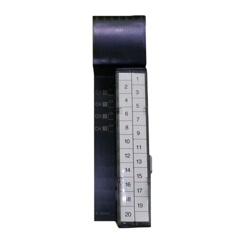
LG MASTER-K Series User manual

User’s Manual
LG Programmable Logic Controller
GLOFA
MASTER-K
LG Industrial Systems
G3F-HSCA
G4F-HSCA
G6F-HSCA

Be sure to read carefully the safety precautions given in data sheet and user’s manual before operating the module
and follow them.
The precautions explained here only apply to the high-speed counting module.
For safety precautions on the PLC system, see the GLOFA PLC GM3/4/6 and MASTER-K200S/300S/1000S CPU
User’s Manuals.
A precaution is given with a hazard alert triangular symbol to call your attention, and precautions are represented
as follows according to the degree of hazard.
However, a precaution followed with can also result in serious conditions.
Both of two symbols indicate that an important content is mentioned, therefore, be sure to observe it.
Keep this manual handy for your quick reference in necessary.
SAFETY PRECAUTIONS
WARNING
!
If not provided with proper prevention, it can cause death or fatal
injury or considerable loss of property.
CAUTION
!
If not properly observed, it can cause a hazard situation to result
in severe or slight injury or a loss of property.
CAUTION
!
CAUTION
!
Design Precautions
▶
Design a safety circuit in the outside of the
PLC for system safety in case of disorder
of the external power or PLC module body.
▶ Otherwise, it can cause injury due to wrong
output or malfunction.
CAUTION
!
▶Do not run I/O signal lines near to high
voltagelineorpowerline.
Separate them as 100 mm or more as
possible.
▶ Otherwise, noise can cause module
malfunction.
CAUTION
!
Installation Precautions
▶
Operate the PLC in the environment conditions given in the general specifications.
▶If operated in other environment not specified in the general specifications, it can cause an
electric shock, a fire, malfunction or damage or degradation of the module
▶Make sure the module fixing projections is inserted into the module fixing hole and fixed.
▶Improper installation of the module can cause malfunction, disorder or falling.

CAUTION
!
Wiring Precautions
▶
When grounding a FG terminal, be sure to provide class 3 grounding which is dedicated to
the PLC.
▶
Before the PLC wiring, be sure to check the rated voltage and terminal arrangement for
the module and observe them correctly.
If a different power, not of the rated voltage, is applied or wrong wiring is provided, it can
cause a fire or disorder of the nodule.
▶
Drive the terminal screws firmly to the defined torque.
If loosely driven, it can cause short circuit, a fire or malfunction.
▶
Be careful that any foreign materials like wire scraps should not enter into the module.
It can cause a fire, disorder or malfunction.
WARNING
!
Test Run and Maintenance
Precautions
▶
Do not contact the terminals
while the power is applied.
It can cause malfunction.
▶
When cleaning or driving a termi-
nal screw, perform them after the
power has been turned off
▶
Do not perform works while the
power is applied, which can
cause disorder or malfunction.
CAUTION
!
▶
Do not separate the module from
the printed circuit board(PCB), or
do not remodel the module.
They can cause disorder, mal-
function, damage of the module
or a fire.
When mounting or dismounting
the module, perform them after
the power has been turned off.
▶Do not perform works while the
power is applied, which can
cause disorder or malfunction.
CAUTION
!
Waste Disposal Precautions
▶
When disposing the module, do it as an industrial waste.

◎
CONTENTS
◎
Chapter 1. INTRODUCTION
Chapter 2. SPECIFICATIONS
2.1 General Specifications
⋯⋯⋯⋯⋯⋯⋯⋯⋯⋯⋯⋯⋯⋯⋯⋯⋯⋯⋯⋯⋯⋯⋯⋯⋯⋯
2-1
2.2 Performance Specifications
⋯⋯⋯⋯⋯⋯⋯⋯⋯⋯⋯⋯⋯⋯⋯⋯⋯⋯⋯⋯⋯⋯⋯⋯
2-2
2.2.1 Basic performance specification ⋯⋯⋯⋯⋯⋯⋯⋯⋯⋯⋯⋯⋯⋯⋯⋯⋯⋯⋯⋯⋯⋯⋯ 2-2
2.2.2 Input specification⋯⋯⋯⋯⋯⋯⋯⋯⋯⋯⋯⋯⋯⋯⋯⋯⋯⋯⋯⋯⋯⋯⋯⋯⋯⋯⋯⋯⋯ 2-3
2.2.3 Limit switch(L/S) input specification ⋯⋯⋯⋯⋯⋯⋯⋯⋯⋯⋯⋯⋯⋯⋯⋯⋯⋯⋯⋯⋯⋯ 2-3
2.2.4 Transister output specification ⋯⋯⋯⋯⋯⋯⋯⋯⋯⋯⋯⋯⋯⋯⋯⋯⋯⋯⋯⋯⋯⋯⋯⋯ 2-3
2.3 Names of Parts and Functions
⋯⋯⋯⋯⋯⋯⋯⋯⋯⋯⋯⋯⋯⋯⋯⋯⋯⋯⋯⋯⋯⋯
2-4
2.3.1 Names of Parts and Functions ⋯⋯⋯⋯⋯⋯⋯⋯⋯⋯⋯⋯⋯⋯⋯⋯⋯⋯⋯⋯⋯⋯⋯⋯ 2-4
2.3.2 Function of LED Indicators ⋯⋯⋯⋯⋯⋯⋯⋯⋯⋯⋯⋯⋯⋯⋯⋯⋯⋯⋯⋯⋯⋯⋯⋯⋯ 2-6
2.3.3 DIP Switch Setting Part ⋯⋯⋯⋯⋯⋯⋯⋯⋯⋯⋯⋯⋯⋯⋯⋯⋯⋯⋯⋯⋯⋯⋯⋯⋯⋯ 2-7
2.3.4 Input / Output Terminal Block ⋯⋯⋯⋯⋯⋯⋯⋯⋯⋯⋯⋯⋯⋯⋯⋯⋯⋯⋯⋯⋯⋯⋯⋯ 2-8
2.4 Interface with External Devices
⋯⋯⋯⋯⋯⋯⋯⋯⋯⋯⋯⋯⋯⋯⋯⋯⋯⋯⋯⋯⋯⋯⋯
2-10
2.5 Output Mode of Encoder
⋯⋯⋯⋯⋯⋯⋯⋯⋯⋯⋯⋯⋯⋯⋯⋯⋯⋯⋯⋯⋯⋯⋯⋯⋯⋯
2-12
2.6 Function Descriptions
⋯⋯⋯⋯⋯⋯⋯⋯⋯⋯⋯⋯⋯⋯⋯⋯⋯⋯⋯⋯⋯⋯⋯⋯⋯⋯⋯
2-13
2.6.1 Operation Modes ⋯⋯⋯⋯⋯⋯⋯⋯⋯⋯⋯⋯⋯⋯⋯⋯⋯⋯⋯⋯⋯⋯⋯⋯⋯⋯⋯⋯⋯ 2-13
2.6.2 Comparision Signal Output ⋯⋯⋯⋯⋯⋯⋯⋯⋯⋯⋯⋯⋯⋯⋯⋯⋯⋯⋯⋯⋯⋯⋯⋯⋯ 2-15
2.6.3 Home Signal ⋯⋯⋯⋯⋯⋯⋯⋯⋯⋯⋯⋯⋯⋯⋯⋯⋯⋯⋯⋯⋯⋯⋯⋯⋯⋯⋯⋯⋯⋯ 2-17
2.6.4 Carry Signal ⋯⋯⋯⋯⋯⋯⋯⋯⋯⋯⋯⋯⋯⋯⋯⋯⋯⋯⋯⋯⋯⋯⋯⋯⋯⋯⋯⋯⋯⋯ 2-18
2.6.5 Borrow Signal ⋯⋯⋯⋯⋯⋯⋯⋯⋯⋯⋯⋯⋯⋯⋯⋯⋯⋯⋯⋯⋯⋯⋯⋯⋯⋯⋯⋯⋯⋯ 2-18
Chapter 3. INSTALLATION AND WIRING
3.1 Installation
⋯⋯⋯⋯⋯⋯⋯⋯⋯⋯⋯⋯⋯⋯⋯⋯⋯⋯⋯⋯⋯⋯⋯⋯⋯⋯⋯⋯⋯⋯⋯⋯
3-1
3.1.1 Installation Ambience ⋯⋯⋯⋯⋯⋯⋯⋯⋯⋯⋯⋯⋯⋯⋯⋯⋯⋯⋯⋯⋯⋯⋯⋯⋯⋯⋯ 3-1
3.2 Wiring Precautions
⋯⋯⋯⋯⋯⋯⋯⋯⋯⋯⋯⋯⋯⋯⋯⋯⋯⋯⋯⋯⋯⋯⋯⋯⋯⋯⋯⋯
3-1
3.3 Wiring Example
⋯⋯⋯⋯⋯⋯⋯⋯⋯⋯⋯⋯⋯⋯⋯⋯⋯⋯⋯⋯⋯⋯⋯⋯⋯⋯⋯⋯⋯⋯
3-2
3.3.1 5VDC Voltage Output Type Encoder ⋯⋯⋯⋯⋯⋯⋯⋯⋯⋯⋯⋯⋯⋯⋯⋯⋯⋯⋯⋯⋯⋯⋯ 3-2
3.3.2 24VDC NPN Open Type Encoder ⋯⋯⋯⋯⋯⋯⋯⋯⋯⋯⋯⋯⋯⋯⋯⋯⋯⋯⋯⋯⋯⋯⋯⋯ 3-3
3.3.3 24VDC PNP Open Collector Encoder ⋯⋯⋯⋯⋯⋯⋯⋯⋯⋯⋯⋯⋯⋯⋯⋯⋯⋯⋯⋯⋯⋯⋯ 3-4

Chapter 4. FUNCTION BLOCK
4.1 Insertion of the Function Block for Hgh Speed Counter on the GMWIN
⋯⋯⋯⋯
4-1
4.2Local Function Block
⋯⋯⋯⋯⋯⋯⋯⋯⋯⋯⋯⋯⋯⋯⋯⋯⋯⋯⋯⋯⋯⋯⋯⋯⋯⋯⋯
4-2
4.2.1The specfication of the preset value(HSC_PRE) ⋯⋯⋯⋯⋯⋯⋯⋯⋯⋯⋯⋯⋯⋯⋯⋯⋯ 4-2
4.2.2The specfication of the comparison value (HSC_CMP) ⋯⋯⋯⋯⋯⋯⋯⋯⋯⋯⋯⋯⋯⋯⋯ 4-3
4.2.3Wrting the operating Information(HSC_WR) ⋯⋯⋯⋯⋯⋯⋯⋯⋯⋯⋯⋯⋯⋯⋯⋯⋯⋯⋯ 4-4
4.2.4Reading the value of the operating status(HSC_RD) ⋯⋯⋯⋯⋯⋯⋯⋯⋯⋯⋯⋯⋯⋯⋯⋯ 4-5
4.3Remote Function Block
⋯⋯⋯⋯⋯⋯⋯⋯⋯⋯⋯⋯⋯⋯⋯⋯⋯⋯⋯⋯⋯⋯⋯⋯⋯⋯
4-6
4.3.1The specification of the preset value (HSCR1PRE) ⋯⋯⋯⋯⋯⋯⋯⋯⋯⋯⋯⋯⋯⋯⋯⋯ 4-6
4.3.2The specification of the comparison value (HSCR1CMP) ⋯⋯⋯⋯⋯⋯⋯⋯⋯⋯⋯⋯⋯⋯ 4-7
4.3.3Writing the operating information (HSCR1WR) ⋯⋯⋯⋯⋯⋯⋯⋯⋯⋯⋯⋯⋯⋯⋯⋯⋯⋯ 4-8
4.3.4 Reading the value of the operating status(HSCR1RD) ⋯⋯⋯⋯⋯⋯⋯⋯⋯⋯⋯⋯⋯⋯⋯ 4-9
4.4Error code on the function block
⋯⋯⋯⋯⋯⋯⋯⋯⋯⋯⋯⋯⋯⋯⋯⋯⋯⋯⋯⋯⋯⋯
4-10
Chapter 5. GM PROGRAMMING
5.1 Programming Examples
⋯⋯⋯⋯⋯⋯⋯⋯⋯⋯⋯⋯⋯⋯⋯⋯⋯⋯⋯⋯⋯⋯⋯⋯⋯⋯
5-1
5.1.1 Enabling the counter operation ⋯⋯⋯⋯⋯⋯⋯⋯⋯⋯⋯⋯⋯⋯⋯⋯⋯⋯⋯⋯⋯⋯⋯ 5-2
5.1.2 Preset ⋯⋯⋯⋯⋯⋯⋯⋯⋯⋯⋯⋯⋯⋯⋯⋯⋯⋯⋯⋯⋯⋯⋯⋯⋯⋯⋯⋯⋯⋯⋯⋯⋯5-3
5.1.3 Setting the comparison value ⋯⋯⋯⋯⋯⋯⋯⋯⋯⋯⋯⋯⋯⋯⋯⋯⋯⋯⋯⋯⋯⋯⋯⋯ 5-4
5.1.4 Setting the magnitude comparison values ⋯⋯⋯⋯⋯⋯⋯⋯⋯⋯⋯⋯⋯⋯⋯⋯⋯⋯⋯⋯ 5-5
5.1.5 Reading the current count value ⋯⋯⋯⋯⋯⋯⋯⋯⋯⋯⋯⋯⋯⋯⋯⋯⋯⋯⋯⋯⋯⋯⋯ 5-6
5.1.6 Enabling the external output ⋯⋯⋯⋯⋯⋯⋯⋯⋯⋯⋯⋯⋯⋯⋯⋯⋯⋯⋯⋯⋯⋯⋯⋯ 5-7
5.1.7 Coincidence reset ⋯⋯⋯⋯⋯⋯⋯⋯⋯⋯⋯⋯⋯⋯⋯⋯⋯⋯⋯⋯⋯⋯⋯⋯⋯⋯⋯⋯ 5-8
5.1.8 Carry / Borrow reset ⋯⋯⋯⋯⋯⋯⋯⋯⋯⋯⋯⋯⋯⋯⋯⋯⋯⋯⋯⋯⋯⋯⋯⋯⋯⋯⋯ 5-9
5.1.9 Enabling the home latch ⋯⋯⋯⋯⋯⋯⋯⋯⋯⋯⋯⋯⋯⋯⋯⋯⋯⋯⋯⋯⋯⋯⋯⋯⋯⋯ 5-10
5.1.10 Read/Write when the high speed counter module Is mounted onto the remote station⋯⋯⋯⋯ 5-11
5.2 Application Examples
⋯⋯⋯⋯⋯⋯⋯⋯⋯⋯⋯⋯⋯⋯⋯⋯⋯⋯⋯⋯⋯⋯⋯⋯⋯⋯⋯
5-13
5.2.1 Program for moving the cart ⋯⋯⋯⋯⋯⋯⋯⋯⋯⋯⋯⋯⋯⋯⋯⋯⋯⋯⋯⋯⋯⋯⋯⋯⋯ 5-13
Chapter 6. BUFFER MEMORY AND I/O SIGNAL CONFIGURATION

6.1 Operating block diagram
⋯⋯⋯⋯⋯⋯⋯⋯⋯⋯⋯⋯⋯⋯⋯⋯⋯⋯⋯⋯⋯⋯⋯⋯⋯
6-1
6.2Input / Output signal configuration
⋯⋯⋯⋯⋯⋯⋯⋯⋯⋯⋯⋯⋯⋯⋯⋯⋯⋯⋯⋯
6-3
6.2.1G3F-HSCA ⋯⋯⋯⋯⋯⋯⋯⋯⋯⋯⋯⋯⋯⋯⋯⋯⋯⋯⋯⋯⋯⋯⋯⋯⋯⋯⋯⋯⋯⋯⋯ 6-3
6.2.2 G4F-HSCA / G6F-HSCA ⋯⋯⋯⋯⋯⋯⋯⋯⋯⋯⋯⋯⋯⋯⋯⋯⋯⋯⋯⋯⋯⋯⋯⋯⋯⋯ 6-5
6.2.3Functions of I/O Signals ⋯⋯⋯⋯⋯⋯⋯⋯⋯⋯⋯⋯⋯⋯⋯⋯⋯⋯⋯⋯⋯⋯⋯⋯⋯⋯ 6-6
6.3Buffer memory configuration
⋯⋯⋯⋯⋯⋯⋯⋯⋯⋯⋯⋯⋯⋯⋯⋯⋯⋯⋯⋯⋯⋯⋯
6-8
6.3.1 Buffer memory configuration ⋯⋯⋯⋯⋯⋯⋯⋯⋯⋯⋯⋯⋯⋯⋯⋯⋯⋯⋯⋯⋯⋯⋯⋯⋯ 6-8
6.3.2 The contents and data configuration of buffer memory ⋯⋯⋯⋯⋯⋯⋯⋯⋯⋯⋯⋯⋯⋯⋯ 6-9
Chapter 7. MK PROGRAMMING
7.1 Buffer Memory Read / Write
⋯⋯⋯⋯⋯⋯⋯⋯⋯⋯⋯⋯⋯⋯⋯⋯⋯⋯⋯⋯⋯⋯⋯⋯
7-1
7.1.1 Read from the Buffer Memory (GET,GETP) ⋯⋯⋯⋯⋯⋯⋯⋯⋯⋯⋯⋯⋯⋯⋯⋯⋯⋯⋯ 7-1
7.1.2 Write to the Buffer Memory (PUT,PUTP) ⋯⋯⋯⋯⋯⋯⋯⋯⋯⋯⋯⋯⋯⋯⋯⋯⋯⋯⋯⋯ 7-3
7.2 Programming Examples
⋯⋯⋯⋯⋯⋯⋯⋯⋯⋯⋯⋯⋯⋯⋯⋯⋯⋯⋯⋯⋯⋯⋯⋯⋯⋯
7-5
7.2.1 Setting Preset Value⋯⋯⋯⋯⋯⋯⋯⋯⋯⋯⋯⋯⋯⋯⋯⋯⋯⋯⋯⋯⋯⋯⋯⋯⋯⋯⋯⋯ 7-5
7.2.2Setting Comparison Value ⋯⋯⋯⋯⋯⋯⋯⋯⋯⋯⋯⋯⋯⋯⋯⋯⋯⋯⋯⋯⋯⋯⋯⋯⋯ 7-7
7.2.3 Setting Out Data ⋯⋯⋯⋯⋯⋯⋯⋯⋯⋯⋯⋯⋯⋯⋯⋯⋯⋯⋯⋯⋯⋯⋯⋯⋯⋯⋯⋯⋯ 7-7
7.2.4 Reading Current Count Value ⋯⋯⋯⋯⋯⋯⋯⋯⋯⋯⋯⋯⋯⋯⋯⋯⋯⋯⋯⋯⋯⋯⋯⋯ 7-8
7.2.5 Enable Output ⋯⋯⋯⋯⋯⋯⋯⋯⋯⋯⋯⋯⋯⋯⋯⋯⋯⋯⋯⋯⋯⋯⋯⋯⋯⋯⋯⋯⋯ 7-8
7.2.6 Enabling Home Latch ⋯⋯⋯⋯⋯⋯⋯⋯⋯⋯⋯⋯⋯⋯⋯⋯⋯⋯⋯⋯⋯⋯⋯⋯⋯⋯⋯ 7-9
7.2.7 Coincidence Reset ⋯⋯⋯⋯⋯⋯⋯⋯⋯⋯⋯⋯⋯⋯⋯⋯⋯⋯⋯⋯⋯⋯⋯⋯⋯⋯⋯⋯ 7-10
7.2.8 Carry / Borrow Reset ⋯⋯⋯⋯⋯⋯⋯⋯⋯⋯⋯⋯⋯⋯⋯⋯⋯⋯⋯⋯⋯⋯⋯⋯⋯⋯ 7-10
7.3 Application Examples
⋯⋯⋯⋯⋯⋯⋯⋯⋯⋯⋯⋯⋯⋯⋯⋯⋯⋯⋯⋯⋯⋯⋯⋯⋯⋯⋯
7-11
7.3.1 Program for moving the cart ⋯⋯⋯⋯⋯⋯⋯⋯⋯⋯⋯⋯⋯⋯⋯⋯⋯⋯⋯⋯⋯⋯⋯⋯⋯ 7-11
7.3.2Program for Control of the Constant Angle rotation of the Turntable ⋯⋯⋯⋯⋯⋯⋯⋯⋯⋯ 7-16
Chapter 8. TROUBLESHOOTING
8.1 Troubleshooting
⋯⋯⋯⋯⋯⋯⋯⋯⋯⋯⋯⋯⋯⋯⋯⋯⋯⋯⋯⋯⋯⋯⋯⋯⋯⋯⋯⋯⋯
8-1
8.1.1 The LED status of High Speed Counter Module ⋯⋯⋯⋯⋯⋯⋯⋯⋯⋯⋯⋯⋯⋯⋯⋯⋯⋯ 8-1
8.1.2 The counting status High Speed Counter Module ⋯⋯⋯⋯⋯⋯⋯⋯⋯⋯⋯⋯⋯⋯⋯⋯⋯⋯ 8-1
8.1.3 The output status of High Speed Counter Module ⋯⋯⋯⋯⋯⋯⋯⋯⋯⋯⋯⋯⋯⋯⋯⋯⋯⋯ 8-1
8.2 Troubleshooting Procedure
⋯⋯⋯⋯⋯⋯⋯⋯⋯⋯⋯⋯⋯⋯⋯⋯⋯⋯⋯⋯⋯⋯⋯⋯
8-2
8.2.1 LED indication Is Incorrect ⋯⋯⋯⋯⋯⋯⋯⋯⋯⋯⋯⋯⋯⋯⋯⋯⋯⋯⋯⋯⋯⋯⋯⋯⋯ 8-2
8.2.2 Count Operations Do Not Execute⋯⋯⋯⋯⋯⋯⋯⋯⋯⋯⋯⋯⋯⋯⋯⋯⋯⋯⋯⋯⋯⋯⋯ 8-3
8.2.3 Counter Value Is Incorrect ⋯⋯⋯⋯⋯⋯⋯⋯⋯⋯⋯⋯⋯⋯⋯⋯⋯⋯⋯⋯⋯⋯⋯⋯⋯ 8-4
8.2.4 Output Operations Do Not Execute ⋯⋯⋯⋯⋯⋯⋯⋯⋯⋯⋯⋯⋯⋯⋯⋯⋯⋯⋯⋯⋯⋯ 8-5
8.3 Error LED List
⋯⋯⋯⋯⋯⋯⋯⋯⋯⋯⋯⋯⋯⋯⋯⋯⋯⋯⋯⋯⋯⋯⋯⋯⋯⋯⋯⋯⋯⋯
8-6
Chapter 9. DIMENSIONS
9.1 Dimensions
⋯⋯⋯⋯⋯⋯⋯⋯⋯⋯⋯⋯⋯⋯⋯⋯⋯⋯⋯⋯⋯⋯⋯⋯⋯⋯⋯⋯⋯⋯⋯⋯
9-1

Chapter 1. INTRODUCTION
1- 1
Chapter 1. INTRODUCTION
This manual describes the specifications, handling instructions, and programming information for the
G3F–HSCA,the G4F–HSCA and the G6F-HSCA.
It is the high speed counting module used with CPU of the GLOFA PLC GM1/2/3/4/6 series and the
MASTER-K200S/300S/1000S series.
The G3F-HSCA is used for GM1/2/3 series and K1000S series, and the G4F-HSCA for GM4 series
and K300S series, the G6F-HSCA for GM6 series and K200S series.
The G3F-HSCA, the G4F-HSCA and the G6F-HSCA consist of 24bit counting part which performs in-
crement or decrement count, an external input part, a comparison part which compares the set value
specified by the user with the current counting value, and an output part which outputs the comparison
results.

Chapter 2. SPECIFICATIONS
2 - 1
Chapter 2. SPECIFICATIONS
2.1 General Specifications
Table 2.1 shows general specifications of the GLOFA GM series and MASTER-K series.
No Item SpecificationsStandards
1Operating ambient
temperature
0 ~55℃(32 ~ 131℉)
2Storage ambient
temperature
-25 ~75℃(-13~167℉)
3Operating ambient
humidity
5 ~95%RH, non-condensing
4Storage ambient
humidity 5 ~95%RH, non-condensing
Occasionalvibration
Frequency
Acceleration
Amplitude
Sweep count
10
≤
f
∠
57 Hz
-
0.075 mm
57
≤
f
≤
150 Hz
0.001Kg
-
Continuous vibration
Frequency
Acceleration
Amplitude
10
≤
f
∠
57 Hz
-
0.035 mm
5Vibration
57
≤
f
≤
150 Hz
4.9
㎨
-
10 times in each
direction for
X, Y, Z
IEC 61131-2
6Shocks*Maximum shock acceleration: 15g
*Duration time :11 ms
*Pulse wave: half sine wave pulse( 3 times in each ofX, Y and Zdirections )
IEC 61131-2
impulse noise ±1,500 V
Electrostatic discharge Voltage :4kV(contact discharge) IEC 61131-2
IEC 1000-4-2
Radiated electromagnetic field 27 ~500 MHz, 10 V/m IEC 61131-2
IEC 1000-4-3
Severity
Level All power
modules
Digital
I/Os
( Ue
≥
24 V)
Digital I/Os
(Ue <24 V)
Analog I/Os
communication
I/Os
7Noise immunity
Fast transient burst noise
Voltage
2kV
1kV
0.25 kV
IEC 61131-2
IEC 1000-4-4
8Operating
atmosphere
Free fromcorrosive gases and excessive dust
9Altitude for use Up to 2,000m(6,562ft)
10 Pollution degree 2or lower
11 Cooling method Self-cooling
[Table 2.1 ] General Specifications
Remark
1) IEC(International Electrotechnical Commission)
:The international civilian organization which produces standards for electrical and electronics industry.
2) Pollution degree
:It indicates a standard of operating ambient pollution level.
The pollution degree 2 means the condition in which normally, only non-conductive pollution occurs.
Occasionally, however, a temporary conductivity caused by condensation shall be expected.

Chapter 2. SPECIFICATIONS
2 - 2
2.2 Performance Specifications
The following show various specifications of the High-speed counting module including basic performance
specifications, input specifications, limit switch input specifications and transistor output specifications.
2.2.1 Basic Performance Specification
Specifications
Item
G3F - HSCA G4F - HSCA G6F - HSCA
I/O Points 32 Points 16 Points
Number of Channels 2 channels1 channel
Signal Phase A, Phase B or Phase Z
Signal level 5 / 12 / 24 VDC (7-13mA)
Counter
input
signal
Signal type Voltage input
Counting range 0 to 16,777,215 (24 Bits Binary)
Counting speed Maximum 50 kHz
Limit switch input 24 VDC
1-phase input Set by program or Phase B is set
Setting
Increment
/Decrement 2-phase input Set by difference of phase automatically
Type Out 1, Out 2(One among ‘>’, ‘=’and ‘<’is selected)
External
output Signal type Transistor output ( open collector output, 10 to 30 V)
Multiplication The multiplication factor for the input pulse may be set to 1, 2 or 4
(Selected by DIP Switch adjustment)
Current consumption 5 VDC,0.3 A 5 VDC,0.25 A 5 VDC,0.18 A
Weight 620 g330 g160 g

Chapter 2. SPECIFICATIONS
2 - 3
2.2.2 Input Specifications
Item Specifications
5VDC (7 mA)
12 VDC (7 mA)Rated input voltage / current
24 VDC (13 mA)
5VDC 4.5 V or more
12 VDC 11 V or more' On ' guarantee voltage
24 VDC 14 V or more
5VDC 0.8 or less
12 VDC 1.5 V or less' Off ' guarantee voltage
24 VDC 2.5 V or less
2.2.3 Limit Switch (L/S) Input Specifications
Item Specifications
Input voltage 24 VDC
' On ' guarantee voltage 19 VDC or more
' Off ' guarantee voltage 6VDC or less
On Delay Time 1.5 ms or less
Off Delay Time 2ms or less
2.2.4 Transistor Output Specifications
Item Specifications
Rated output 24 VDC, 200 mA
Leakage current 50 μA or less
Saturated voltage 1.3V
On Delay Time 50 μs or less
Off Delay Time 50 μs or less

Chapter 2. SPECIFICATIONS
2 - 4
2.3 Names of Parts and Functions
2.3.1 Names of Parts and Functions
The names of parts and functions of the high speed counter module are shown as below
Dip switch
Setting part
LED
Indicators
Input/
output
terminal
block

Chapter 2. SPECIFICATIONS
2 - 5
LED
Indicators
Input/
output
terminal
block
Dip switch
setting part
K3F-HSCA
L/S
OUT2
PRESET
OUT1
READY
Φ
A
Φ
B
Φ
Z
24V
12V
5V
COM
Φ
A
24V
Φ
B
Φ
Z
24V
0V
24V
0V
OUT1
OUT2
0V
L/S
PRE
-SET
24V
12V
5V
COM
24V
12V
5V
COM
K3F-HSCA
+
-
LED
Indicators
Input/
output
Connector
3) G6F-
G6F-HSCA
G6F-HSCA

Chapter 2. SPECIFICATIONS
2 - 6
2.3.2 Function of LED Indicators
No. Description
①Power LED
Turns On when the power is applied.
②
Error LED
Turns on for 0.5 sec when the power is applied and
then turns off if the system is normally running.
Flickers with 0.1 sec, 0.2 sec or 0.3 sec cycle
according to the error content, If an error has
occurred.
③
Phase A pulse input LED
Turns on when voltage is applied to phase A input
terminal.
④
Phase B pulse input LED
Turns on when voltage is applied to phase B input
terminal
⑤
Phase Z pulse input LED
Turns on when voltage is applied to phase B input
terminal
⑥
Limit switch input LED
Turns on when voltage is applied to limit switch
input terminal
⑦OUT1 output LED
Indicate the magnitude comparison result of CMP 1
⑧OUT2 output LED
Indicate the magnitude comparison result of CMP 2
⑨
Preset Switch Input (PRESET)
Turns on when voltage is applied to preset switch
input terminal
K3F-HSCA
READY
Φ
A
Φ
B
Φ
C
L/S
OUT2
PRESET
OUT1
G3F-HSCA
ERROR
POWER
LIMIT
G4F-HSCA
ERRO
R
POWE
R
G6F-HSCA
①
③
④
⑤
⑥
⑨
⑦
⑧

Chapter 2. SPECIFICATIONS
2 - 7
2.3.3 DIP Switch Setting Part
The DIP Switch settings are used for phase-2/ phase-1 operation mode specification, Increment /
Decrement count method specification at 1-phase operation, and multiplication specification at 2-phase
operation.
G3F-HSCA G4F-HSCA/G6F-HSCA
Switch Functions
G3F-HSCA
channel
0channel 1
G4F-HSCA,
G6F-HSCA Status Descriptions
On Specifies the 2 –phase pulse operation mode.
SW 1 SW 5 SW 1
Off Specifies the 1 –phase pulse operation mode.
On Specifies the phase B pulse input mode as
increment/decrement count method at 1 –phase
pulse inputs
SW 2 SW 6 SW 2
Off Specifies the program input mode as
increment/decrement count method at 1 –phase
pulse inputs
On
On Specifies as multiplicate 1
On
Off Specifies multiplicate 2
Off
On No multiplication is applied
SW 3
SW 4
SW 7
SW 8
SW 3
SW 4
Off
Off Specifies multiplicate 4
Channel 0
Channel 1

Chapter 2. SPECIFICATIONS
2 - 8

Chapter 2. SPECIFICATIONS
2 - 9
2.3.4 Input / Output Terminal Block
1) G3F-HSCA/G4F-HSCA
Remark
The above input/output terminals the CH0 and CH1 of the G3F–HSCA use the same input/output
terminals as shown above.
The G4F–HSCA input/output terminal’s configuration is also same as above.
●Phase B pulse Input Terminal
One of 24V, 12V and 5V is selected
●Phase A pulse Input Terminal
One of 24V, 12V and 5V is selected
●Comparison Output Terminal
Transistor Open Collector Output
●External Power Input Terminal
24VDC
●Phase Z pulse Input Terminal
One of 24V, 12V and 5V is selected
●Limit Switch Input Terminal
24VDC

Chapter 2. SPECIFICATIONS
2 - 10
2) G6F-HSCA
Remark
The G6F-HSCA module has external preset input terminal(15, 16).
And it is possible to used to preset value setting signal of external.
24V
12V
5V
COM
24V
12V
5V
COM
24V
12V
5V
COM
24V
0V
24V
0V
OUT1
OUT2
0V
24V
Φ
A
Φ
B
Φ
Z
L/S
PRE
1234
5
6
7891011121314151617
18
202122
19
23
24252627
28
2930
31
323334
35
3637
●Phase B pulse Input Terminal
One of 24V, 12V and 5V is selected
●Phase A pulse Input Terminal
One of 24V, 12V and 5V is selected
●Comparison Output Terminal
Transistor Open Collector Output
●External Power Input Terminal
24VDC
●Phase Z pulse Input Terminal
One of 24V, 12V and 5V is selected
●Limit Switch Input Terminal
24VDC
●Preset Switch Input Terminal
24VDC

Chapter 2. SPECIFICATIONS
2 - 11
2.4 Interface with External Devices
Table 2.1 and Table 2.2 shows the list for interface with external devices.
1) G3F-HSCA/G4F-HSCA
Termina
l No.
I/O Internal Current CH
0C
H1
Signal Name Operatio
n
Input
guarantied
Voltage
On 14~26.4 V
121 24 V, Phase A
pulse input Off 2.5 V
On 11~13.2 V
222 12 V, Phase A
pulse input Off 1.5 V
On 4.5~5.5 V
323 5V, Phase A
pulse input Off 0.8 V or
less
424 COM On 14~26.4 V
525 24 V, Phase B
pulse input Off 2.5 V
On 11~13.2 V
626 12 V, Phase B
pulse input Off 1.5 V
On 4.5~5.5 V
727 5V, Phase B
pulse input Off 0.8 V or
less
828 COM On 14~26.4 V
929 24 V, Phase Z
pulse input Off 2.5 V
On 11~13.2 V
10 30 12 V, Phase Z
pulse input Off 1.5 V
On 4.5~5.5 V
11 31 5V, Phase Z
pulse input Off 0.8 V or
less
Input
12 32 COM
On 19~26.4 V
13 33 L/S input, 24
VOff 6V or less
Input
14 34 L/S COM
15 35 Open collector
output OUT1
16 36 Open collector
output OUT1
Rated output:
24VDC, 200 mA
Response time:
Off→On 50 ㎲or less
On→Off 50 ㎲or less
Output 17 37
External
power supply
output
24 VInput voltage
10.2 ~ 30 V
330Ω
330Ω
330Ω

Chapter 2. SPECIFICATIONS
2 - 12
18 38
External
power supply
COM
0V
[Table 2.1]External interface list ( G3F-HSCA / G4F-HSCA )
2) G6F-HSCA
I/O Internal Current Terminal
pin No. Signal Name Operatio
n
Input
guarantied
Voltage
On 14~26.4 V
124 V, Phase
A pulse input Off 2.5 V
On 11~13.2 V
212 V, Phase
A pulse input Off 1.5 V
On 4.5~5.5 V
35V, Phase A
pulse input Off 0.8 V or
less
4COM On 14~26.4 V
524 V, Phase
B pulse input Off 2.5 V
On 11~13.2 V
612 V, Phase
B
pulse input Off 1.5 V
On 4.5~5.5 V
75V, Phase B
pulse input Off 0.8 V or
less
8COM On 14~26.4 V
924 V, Phase
Z pulse input Off 2.5 V
On 11~13.2 V
10 12 V, Phase
Z pulse input Off 1.5 V
On 4.5~5.5 V
11 5V, Phase Z
pulse input Off 0.8 V or
less
Input
12 COM On 19~26.4 V
13 L/S input 24
VOff 6V or less
14 L/S COM On 19~26.4 V
15 Preset input
24V Off 6V or less
Input
16 L/S COM
17 Open
collector
output OUT1
Output
18 Open
collector
output OUT2
Rated output:
24VDC, 200 mA
Response time:
Off→On 50 ㎲or less
On→Off 50 ㎲or less
3.3
㏀
1.2
㏀
330
Ω
820
Ω
3.3
㏀
1.2
㏀
330
Ω
820
Ω
3.3
㏀
1.2
㏀
330
Ω
820
Ω
2.2
㏀
270
Ω
2.2
㏀
270
Ω
This manual suits for next models
4
Table of contents
Other LG Controllers manuals

LG
LG Becon PREMTA000 Product guide

LG
LG MASTER-K10S1 User manual

LG
LG PQCSB101S0 User manual

LG
LG PC Central Controller User manual

LG
LG MASTER-K200S User manual

LG
LG LKD1000 User manual

LG
LG PWFCKN000 User manual

LG
LG PQCSA001T0 Quick start guide

LG
LG PC Central Controller User manual

LG
LG MultiSITE MS8000 Series User manual