2
0871EN October 2020
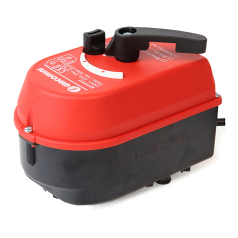
ActuAtor for mixing vAlves
0÷10 V proportional actuator for r296 and r297
mixing ValVes or r274, r274n zone ValVes
K275-1 series
DIP switches settings
With DIP switches inside the actuator is possible to set the following
parameters:
1)
2)
3, 4)
0-10 V 2-10 V 5-10 V0-5 V
5)
•DIP1 - Setting the opening direction of the valve:
ON: clockwise opening direction (CW)
OFF: counterclockwise opening direction (CCW)
•DIP2 - Control signal:
ON: inverse
OFF: direct
•DIP3, 4 - Range setting:
See the table
•DIP5 - Control signal:
ON: I (mA)
OFF: U (V)
Note.
During changing position of DIP1 is performed calibration proces.
The actuator turns into left and right position. During proces leave
the button for manual control in position AUTO.
• Operation to set the DIP switches
1) Remove the cover by unscrewing the 4 screws
2) With a small screwdriver move the DIP switches to the desired position
3) Put the protection cap back in its original position
Manual control
In the case of power failure or for service purposes, user can manually operate
with the actuator.
Note.
When the button for manual
operation is in MAN position,
the actuator stays in temporary
position regardless of control
signal.
90°90°
1
2
AUTO
MAN
1) With a screwdriver push
and turn o the button to the
MAN position.
2) Manually move the handle
to desired position.
Installation
Note: installation on the valves
To correctly install the K275Y013 actuator on Giacomini valves,
refer to the instructions of the valves.
Indicator position
According to the position of DIP switches selection, set the indicator
regarding to your application.
DIP1 = OFF (factory default) DIP1 = ON
Recommended mounting position
Electrical connection
Warning.
Make sure the power supply voltage is disconnected
while the connections are being carried out.
Warning.
Make and check the electrical connections before powering the
system. Short circuits or incorrectly connected cables could cause
permanent damage to the electrical components of the actuator.
BLK
1
BRW
2
BLU
3
RED
4
AC
24 V~
DC 0(2)...10 V
(-)
Y (+)
Feedback 0...10 V
(+)
Wire color Function
(BLK) Black
Supply 24 Vac
(BRW) Brown
(BLU) Blue Controll signal 0÷10 Vdc
(RED) Red Feedback signal 0÷10 Vdc
