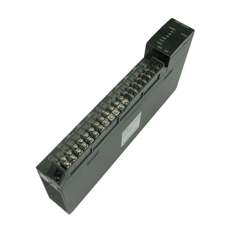
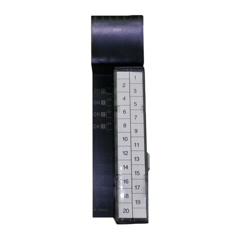
LG G3L-PUEA User manual

LG Programmable Logic Controller
Profibus-DP Module
G3L-PUEA
G3L-PUEB
G4L-PUEA
G4L-PUEB
G6L-PUEA
G6L-PUEB
G7L-PBEA
USER’S MANUAL
GLOFA
MASTER-K
Before using, please read ‘ Notices for the safety ’thoroughly.
Please keep this user’s manual in the place where the user can find easily.

Notices for the Safety
‘Notices for the Safety’ should be complied by the user to use the
product safely and correctly to prevent the occurrence of any
accident or danger.
‘Notices for the Safety’ is divided by “Danger”, ”Warning” and ”Caution”
and each meaning is as follows :
■ The meanin
g
of s
y
mbols used in the
p
roduct and user’s manual is as follows :
This symbol is to take care for the items or operation that may occur the
danger.
When you find this symbol, you should read the instructions carefully to
avoid the danger occurrence.
This symbol is to take care as the electric shock may occur under
the specific condition.
In case of violating the instructions, it may cause the
significant injury or death immediately.
In case of violating the instructions, it may cause
the significant injury or death.
In case of violating the instructions, it may cause
the slight injury or product damage.
Danger
Warning
Caution

■ Notices in Design
■ Notices in Installation
■ Notices in Wiring
I/O Signal/Communication cables shall be designed apart at least 100mm from high voltage
cable or power cable to avoid the influence caused by the noise or the change of magnetic filed.
It may cause the malfunction by the noise.
In case that installation environment has lots of vibration, cares should be taken not to apply the
vibration to the product directly.
The inflow of metal particle is not permitted as it may cause the malfunction of the product.
Caution
PLC should be used in the environment condition described in the general standard.
If used out of general standard, it may cause the electric shock, fire, malfunction, damage of
product or furious flames etc.
Make sure that the module is fixed correctly.
If not installed the module correctly, it may cause the malfunction, failure or falling.
For the grounding of FG terminal, you should use the 3rd class grounding only for PLC.
If not grounding, it may cause the malfunction.
The wiring in PLC should be connected after checking the rating voltage of the product and
terminal layout.
If connected to the different power from the rating or wrong wiring, it may cause the fire or
failure.
In case of wiring, the screw of terminal should be tightened by standard torque.
If the screw of terminal is loosened, it may cause the cutoff or malfunction.
Cares should be taken to avoid the inflow of foreign materials such as wiring dregs inside the
module.
Caution
Caution

■ Notices in Startup and Maintenance
■ Notices in Disposal
Do not remove PCB from the module case or remodel the module. It may cause the failure,
malfunction, damage of the product or fire. The installation and removal of the module should
be done after POWER OFF.
The change of battery should be done in the state of POWER ON.
In case of changing in the state ‘OFF’, the program may be damaged.
Do not touch the terminal in the state that the power is applied. It may cause the malfunction or
electric shock.
When the product is disposed, this should be treated as industry waste.
Caution
Caution
Warning

REVISION HISTORY
Issue Date Manual No. Revised Content
’04.4 10310000334 First edition issued.
User’s Manual no. is marked on the right bottom side of the back cover.

CHAPTER 1 OVERVIEWxxxxxxxxxxxxxxxxxxxxxxxxxxxxxxxxxxxxxxxxxxxxxxxxxxxxxxxxxxxxxxxxxxxxxxx1-1 ~ 1-2
1.1 Notices in usingxxxxxxxxxxxxxxxxxxxxxxxxxxxxxxxxxxxxxxxxxxxxxxxxxxxxxxxxxxxxxxxxxxxxxxxxxxxxxxxx 1-2
CHAPTER 2 TERMINOLOGYxxxxxxxxxxxxxxxxxxxxxxxxxxxxxxxxxxxxxxxxxxxxxxxxxxxxxxxxxxxxxxxxx2-1 ~ 2-2
CHAPTER 3 GENERAL SPECIFICATIONxxxxxxxxxxxxxxxxxxxxxxxxxxxxxxxxxxxxxxxxxxxxxxxx3-1 ~ 3-2
3.1 General Specificationxxxxxxxxxxxxxxxxxxxxxxxxxxxxxxxxxxxxxxxxxxxxxxxxxxxxxxxxxxxxxxxxxxxxxxxxxx 3-1
3.2 Pnet Telecommunication module structurexxxxxxxxxxxxxxxxxxxxxxxxxxxxxxxxxxxxxxxxxxxx 3-2
CHAPTER 4 PERFORMANCE SPECIFICATIONxxxxxxxxxxxxxxxxxxxxxxxxxxxxxxxxxxxxxxxxxxxxxxx4-1
4.1 Telecommunication Specificationxxxxxxxxxxxxxxxxxxxxxxxxxxxxxxxxxxxxxxxxxxxxxxxxxxxxxxxxxx 4-1
CHAPTER 5 SYSTEM CONFIGURATIONxxxxxxxxxxxxxxxxxxxxxxxxxxxxxxxxxxxxxxxxxxxxxxxxxxxxxxxxx5-1
5.1 Profibus-DP System xxxxxxxxxxxxxxxxxxxxxxxxxxxxxxxxxxxxxxxxxxxxxxxxxxxxxxxxxxxxxxxxxxxxxxxxxx 5-1
CHAPTER 6 TELECOMMUNICATION CONFIGURATIONxxxxxxxxxxxxxxxxxxxxxxx6-1 ~ 6-61
6.1 High speed linkxxxxxxxxxxxxxxxxxxxxxxxxxxxxxxxxxxxxxxxxxxxxxxxxxxxxxxxxxxxxxxxxxxxxxxxxxxxxxxxx 6-1
6.1.1 Overviewxxxxxxxxxxxxxxxxxxxxxxxxxxxxxxxxxxxxxxxxxxxxxxxxxxxxxxxxxxxxxxx xxxxxxxxxxxxxxxxx 6-1
6.1.2 Operation procedure by high speed linkxxxxxxxxxxxxxxxxxxxxxxxxxxxxx 6-2
6.1.3 SyCon xxxxxxxxxxxxxxxxxxxxxxxxxxxxxxxxxxxxxxxxxxxxxxxxxxxxxxxxxxxxxxxxxxxxxxxxxxxxxxxxxx 6-2
6.1.4 High speed link parameter setting in GMWINxxxxxxxxxxxxxxxxxxxxxxxxx 6-11
6.1.5 High speed link operation in GMWIN xxxxxxxxxxxxxxxxxxxxxxxxxxxxxxxxxxxx 6-16
6.1.6 High speed link information in GMWIN xxxxxxxxxxxxxxxxxxxxxxxxxxxxxxxxx 6-17
6.1.7 High speed link parameter setting in KGLWINxxxxxxxxxxxxxxxxxxxxxxx 6-22
6.1.8 Speed calculation of high speed linkxxxxxxxxxxxxxxxxxxxxxxxxxxxxxxxxxx 6-25
6.2 Example Program xxxxxxxxxxxxxxxxxxxxxxxxxxxxxxxxxxxxxxxxxxxxxxxxxxxxxxxxxxxxxxx xxxxxxxxxxxx 6-28
6.2.1 Pnet master slave telecommunication in GMWINxxxxxxxxxxxxxxxxxxxxxx 6-28
6.2.2 Smart I/O Pnet master slave telecommunication in GMWINxxxxxx 6-38
6.2.3 Pnet master slave telecommunication in KGLWINxxxxxxxxxxxxxxxxxxxxx 6-46
6.2.4 Smart I/O Pnet master slave telecommunication in KGLWINxxxxxxx 6-55
Table of Contents

CHAPTER 7 DIAGNOSIS FUNCTIONxxxxxxxxxxxxxxxxxxxxxxxxxxxxxxxxxxxxxxxxxxxxxxxxxxxxx7-1 ~ 7-2
7.1 LED xxxxxxxxxxxxxxxxxxxxxxxxxxxxxxxxxxxxxxxxxxxxxxxxxxxxxxxxxxxxxxxxxxxxxxxxxxxxxxxxxxxxxxxxxxxxxxxxx 7-1
CHAPTER 8 INSTALLATION & STARTUPxxxxxxxxxxxxxxxxxxxxxxxxxxxxxxxxxxxxxxxxxxxxxxx8-1 ~ 8-7
8.1 Installation xxxxxxxxxxxxxxxxxxxxxxxxxxxxxxxxxxxxxxxxxxxxxxxxxxxxxxxxxxxxxxxxxxxxxxxxxxxxxxxxxxxxxxxx 8-1
8.1.1 Notices in installationxxxxxxxxxxxxxxxxxxxxxxxxxxxxxxxxxxxxxxxxxxxxxxxxxxxxxxxxxxxxxxx 8-1
8.1.2 Cable installationxxxxxxxxxxxxxxxxxxxxxxxxxxxxxxxxxxxxxxxxxxxxxxxxxxxxxxxxxxxxxxxxxxxxx 8-2
8.2 Startupxxxxxxxxxxxxxxxxxxxxxxxxxxxxxxxxxxxxxxxxxxxxxxxxxxxxxxxxxxxxxxxxxxxxxxxxxxxxxxxxxxxxxxxxxxxxxx 8-4
8.2.1 Notices in system configurationxxxxxxxxxxxxxxxxxxxxxxxxxxxxxxxxxxxxxxxxxxxxxxxxx 8-4
8.2.2 Checklist before startupxxxxxxxxxxxxxxxxxxxxxxxxxxxxxxxxxxxxxxxxxxxxxxxxxxxxxxxxxxx 8-4
8.3 Maintenance & Checkingxxxxxxxxxxxxxxxxxxxxxxxxxxxxxxxxxxxxxxxxxxxxxxxxxxxxxxxxxxxxxxxxxxxx 8-6
8.3.1 Daily checkingxxxxxxxxxxxxxxxxxxxxxxxxxxxxxxxxxxxxxxxxxxxxxxxxxxxxxxxxxxxxxxxxxxxxxxxx 8-6
8.3.2 Regular checkingxxxxxxxxxxxxxxxxxxxxxxxxxxxxxxxxxxxxxxxxxxxxxxxxxxxxxxxxxxxxxxxxxxxx 8-7
CHAPTER 9 TROUBLE SHOOTINGxxxxxxxxxxxxxxxxxxxxxxxxxxxxxxxxxxxxxxxxxxxxxxxxxxxxxxx9-1 ~ 9-9
9.1 Basic procedure of Trouble shootingxxxxxxxxxxxxxxxxxxxxxxxxxxxxxxxxxxxxxxxxxxxxxxxxxxxxx 9-1
9.1.1 Hardware Errorxxxxxxxxxxxxxxxxxxxxxxxxxxxxxxxxxxxxxxxxxxxxxxxxxxxxxxxxxxxxxxxxxxxxxxx 9-2
9.1.2 Interface Errorxxxxxxxxxxxxxxxxxxxxxxxxxxxxxxxxxxxxxxxxxxxxxxxxxxxxxxxxxxxxxxxxxxxxxxxxx 9-3
9.1.3 Network Errorxxxxxxxxxxxxxxxxxxxxxxxxxxxxxxxxxxxxxxxxxxxxxxxxxxxxxxxxxxxxxxxxxxxxxxxxx 9-4
9.1.4 CPU and Interface error during operationxxxxxxxxxxxxxxxxxxxxxxxxxxxxxxxxxxx 9-5
9.1.5 High speed parameter error xxxxxxxxxxxxxxxxxxxxxxxxxxxxxxxxxxxxxxxxxxxxxxxxxxx 9-6
9.1.6 High speed link operation error xxxxxxxxxxxxxxxxxxxxxxxxxxxxxxxxxxxxxxxxxxxxxxxx 9-7
9.1.7 GMWIN/KGLWIN communication time outxxxxxxxxxxxxxxxxxxxxxxxxxxxxxxxxxx 9-8
9.1.8 GMWIN/KGLWIN internal communication errorxxxxxxxxxxxxxxxxxxxxxxxxxxx 9-9
CHAPTER 10 EXTERNAL DIMENSIONxxxxxxxxxxxxxxxxxxxxxxxxxxxxxxxxxxxxxxxxxxxxxxxxxxxxxxxxxx10-1

CHAPTER 1 OVERVIEW
1-1
CHAPTER 1 OVERVIEW
This user’s manual describes GLOFA-GM/MASTER-K Profibus (hereinafter referred as‘Pnet’) which is
Profibus module among network modules of PLC system technically in detail.
Please refer to the following user’s manuals to prepare the program.
zGLOFA-GM PLC Command collection
zGLOFA-GM PLC GMWIN User’s manual
zMASTER-K PLC Command collection
zMASTER-K PLC KGLWIN User’s manual
For Pnet system configuration, cares should be taken to the followings
·GLOFA-GM PLC GMWIN Program Tool: more than Ver 3.4
·GLOFA GM1/2 CPU : more than Ver 3.2
·GLOFA GM3 CPU : more than Ver 2.4
·GLOFA GM4 CPUA/CPUB/CPUC : Ver 2.5/ Ver 2.5/ more than Ver 2.0
·GLOFA GM6 CPUA/CPUB/CPUC : Ver 1.8/ Ver 1.8/ more than Ver 1.8
·GLOFA GM7 CPU : more than Ver 1.5
·MASTER-K PLC KGLWIN Program Tool: more than Ver 3.2
·MASTER-K 1000S CPU : more than Ver 3.0
·MASTER-K 300S CPU : more than Ver 3.0
·MASTER-K 200S CPU : more than Ver 2.5
·MASTER-K 120S CPU : more than Ver 1.1
·MASTER-K 80S CPU : more than Ver 1.5
The features of GLOFA Pnet are as follows :
zInternational standard : EN 50170
zDevice type : Profibus DP Master/ Slave
zAuto Baud Rate Detect : support
zSync mode : support
zFreeze mode : support
zMax. input data : 64 byte/Slave
zMax. output data : 64 byte/Slave
zMax. data size : 128 byte/Slave, (1kbytes or 7kbytes)/Master
zCommunication speed : 9.6K, 19.2K, 93.75K, 187.5K, 500K, 1.5M, 3M, 6M, 12M
zModular Station : support

CHAPTER 1 OVERVIEW
1-2
1.1 Notices in using
When you install this device, cares should be taken to the following items for the reliability and safety of
system.
Items Classification Description
Condition •When installing this device, the use temperature should be 0 ~
55℃ for the part elements.
•Direct exposure to the direct ray of light is not allowed.
Temperature
Action •If the temperature is high, the fan or air conditioner is required
while you should maintain the proper temperature if the
temperature is low.
Condition •No dew by a sudden change of temperature.
•Install inside the control panel available for water-proof or
vibration resistance.
Dew
condensation
Action •The temperature change due to frequent power On/Off may
cause the dew condensation. In this case, keep the power ON
even in the night time.
Condition •Install in the place free from impact or vibration.
Impact
Action •In case of serious impact or vibration, use the vibration-resistant
rubber to prevent from applying the impact or vibration to the
device.
Condition •Install in the place having no corrosive gas.
Gas
Action •In case of inflow of the corrosive gas from outside, it is required
to take measures for air conditioning of the control panel where
installed the device.
Condition •Install in the proper place for the electric magnetic field.
EMC
environment Action •Select the correct path of the cables in case of wiring.
•Check if the sheltering of the control panel is done properly.
•For the lighting inside the control panel, use the incandescent
lamp instead fluorescent lamp.
•Power module should be grounded on the standard electric
potential.

CHAPTER 2 TERMINOLOGY
2-1
CHAPTER 2 TERMINOLOGY
Profibus
Profibus is a protocol designated as German standard DIN 19245, developed by Bosch, Siemens,
Klockener-Moeller in Germany and also a network designated as European standard EN50170 together
with WorldFIP, P-NET.
Profibus is used for the real time communication between field equipments in the area of production
automation, processing control, building automation etc. and the product group is divided into Profibus-
FMS (Fieldbus Message Specification), Profibus-DP (Decentralized Periphery), Profibus-PA(Process
Automation).
Profibus-FMS
This is a solution for the general purpose providing the communication function on the cell level. The
services provided include program file to run the field equipment, the function to send the data related to
the program file, the function to control the program remotely through network, and the function to
manage various accidents that may occur while operating the control or automation system.
Profibus-DP
This is a communication system to send the real time data between field equipments within the short
time and replace the existing communication system using an analog signal of 24V and 4-20mA with a
high speed digital communication mode. The examples for application are the communication between
field equipments such as various kinds of sensor or actuator installed in PLC or in the field.
Profibus-PA
This is designed especially for the processing automation and enables to connect the sensor and
actuator by one common bus line with the embedded safety device, and supply the power to the data
communication on bus by using 2-wire technology in accordance with international standard IEC 1158-2.
Sycon
This is a Profibus Network Configuration Tool. When using a master module (G3/4/6L-PUEA/PUEB) of
LGIS, it is required to configure Pnet by using Sycon and download the information to the relevant master
module.
GSD file
This is an electronic device data sheet that includes manufacturer, device name, hardware/ software
sales, support transmitting rate, master related specification (max. number of connectable slave,
upload/download option etc.) and slave related specification (number and type of I/O channels, diagnosis
text specification and module information available with modular device).
EDD (Electronic Device Description)
This describes the registration information of Profibus field device generally and allows to explain the
complicated automation system as well as simple field device (sensor and/or actuator) regardless of
manufacturer. The device description is provided in electronic format made by the manufacturer per
device. EDD file should be read by engineering tool and enables to simplify the Profibus system setting.
This file describes the variables and the function of the device and contains the elements for operation
and visualization.

CHAPTER 2 TERMINOLOGY
2-2
Broadcast Communication
This is to send the message not recognized by Operation Station to all station (Master, Slave).
Multicast Communication
This is to send the not recognized message to the pre-fixed Station group (Master, Slave) by Operation
Station.

CHAPTER 3 GENERAL SPECIFICATION
3-1
CHAPTER 3 GENERAL SPECIFICATION
3.1 General Specification
The General Specification for the communication module of GLOFAseries and MASTER-K series is as follows:
No. Items Specification Reference
1 Use Temperature 0 ~ 55 °C
2 Storage Temp. −25°C ~ +70 °C
3 Use humidity 5 ~ 95%RH, no dew
4 Storage humidity 5 ~ 95%RH, no dew
In case of Intermittent vibration -
Frequency Acceleration Amplitude Times
10 ≤f <57Hz −0.075mm
57 ≤f ≤150Hz 9.8m/s2{1G} −
In case of Continuous vibration
Frequency Acceleration Amplitude
10 ≤f <57Hz −0.035mm
5 Vibration-resistant
57 ≤f ≤150Hz 4.9m/s2{0.5G} −
X, Y, Z
10 times
each direction
IEC61131-2
6 Impact-proof
•Max. impact acceleration : 147 m/s2{15G}
•Application time : 11ms
•Pulse wave type : semi-sine wave pulse (3 times each direction X,Y,Z) IEC61131-2
Square wave
impulse noise ±1,500 V LGIS internal
test standard
Electrostatic
discharge Voltage : 4kV (Touch discharge) IEC61131-2
IEC1000-4-2
Radiant
electromagnetic
field noise 27 ~ 500 MHz, 10 V/m IEC1131-2,
IEC1000-4-3
Classi-
fication Power
modul
e
Digital I/O
(more than 24V)
Digital I/O
(less than 24V)
Analog I/O
Communication
interface
7 Noise-resistant
Fast transient
/ Bust noise
Voltage 2kV 1kV 0.25kV
IEC1131-2
IEC1000-4-4
8 Surrounding
environment No corrosive gas, no dust
9 Use altitude Less than 2,000m
10 Pollution Less than 2
11 Cooling method Natural air-conditioning
Table 3.1 General Specification
Note
1) IEC(International Electrotechnical Commission) : International civil community that promotes international cooperation
for standardization of electric/electro technology, publishes international standard and operates suitability assessment
system related to the above.
2) Pollution Degree : An index to indicates the pollution degree of used environment that determines the insulation
performance of the device. For example, pollution degree 2 means the state to occur the pollution of non-electric
conductivity generally, but the state to occur temporary electric conduction according to the formation of dew.

CHAPTER 3 GENERAL SPECIFICATION
3-2
3.2 Pnet I/F Module Configuration
No. Names Description
LED indicator Refer to LED display contents.
Profibus-DP
connector Connector for Profibus network (D-SUB 9 pin connector, female type)
Configuration
connector
Connector to download the layout diagram of the prepared Profibus network, by
using configuration tool.(D-SUB 9 pin connector, female type, refer to cable
connection drawing.)
Station no. switch Station no. switch of slave module (1~126 stations setting)
Extension connector Connector to connect the extension module.
Table 3.2 Module Configurations
*G3L-PUEB, G4L-PUEB, G6L-PUEB are the same configuration.

CHAPTER 4 PERFORMANCE SPECIFICATION
4-1
CHAPTER 4 PERFORMANCE SPECIFICATION
4.1 Communication Specification
Type
Items G3/4/6L-PUEA G3/4/6L-PUEB G7L-PBEA
Module type Master Slave
Network type Profibus-DP
Standard EN50170/DIN19245
Interface RS-485(electric power)
Transmission mode Bus mode
Modulation mode NRZ
MAC Local token ring Poll
Total extension length &
speed
1000m(9.6k~187kbps)
400m(500kbps)
200m(1.5Mbps)
100m(3M~12Mbps)
Max. no. of connection per
network 126 stations
Max. no. of connection per
segment 32 stations
Use cable Electric : twisted pair cable
Max. communication point 1kbyte 7kbytes 64byte / slave
Communication parameter
setting
Configuration tool only for
GMWIN/KGLWIN high speed link
parameter
GMWIN
communication
parameter
(in case of using GM7
basic module)
KGLWIN
communication
parameter
(in case of using
K80S basic module)
Internal consumption
current (mA) 542/544/505 594/656/682 337
Weight (g) 373/230/135 373/230/135 204
Table 4.1 Communication specifications

CHAPTER 5 SYSTEM CONFIGURATION
5-1
CHAPTER 5 SYSTEM CONFIGURATION
5.1 Profibus-DP System
GM6
G6L-PUEA/PUEB
GMWIN
GM7/K80S,K120S
G7L-PBEA
SmartI/O
GPL-RY2A/C
GPL-D24A/C
GPL-DT4A/A1/B/C/C1
GPL-TR4A/A1/B/C/C1
SmartI/O
GPL-D22A/C
GPL-TR2A/A1/C1
GPL-TR2B/C
GM3/K1000S
G3L-PUEA/PUEB
GM4/K300S
G4L-PUEA/PUEB
SIEMENS PLC
CNC
Sycon
Configuration software
LG PLC
SmartI/O GM7/K80S,K120S
G7L-PBEA

CHAPTER 6 COMMUNICATION FUNCTION
6-1
CHAPTER 6 COMMUNICATION FUNCTION
zSupports only the high speed link communication.
zParameter setting and configuration in SyCon and GMWIN/KGLWIN.
zSets only sending/receiving area in GMWIN high speed link parameter setting.
zThe sending/receiving data shall be saved and sent continuously from the setting area. (e.g. similar to
the continued MAP of MASTER-K.)
zThe number of sending/receiving and slave area per slave station shall be set using a SyCon and
downloaded by master module using a Configuration port.
zThe number of sending/receiving is available up to 512byte/3584byte respectively according to the dot
board type.
zThe number of sending/receiving per slave station shall be set by byte (set in SyCon).
zThe communication starts through GMWIN/KGLWIN high speed link allowable setting function.
6.1 High Speed Link
6.1.1 Overview
High speed link is a communication method between GLOFA-GM/MASTER-K PLC
communication modules that enables to receive the data by high speed link parameter setting,
and a high speed data transmitting service that the user can set the sending/receiving data size,
sending/receiving period, sending/receiving area or saving area in the parameter and exchange
the data by using GMWIN/KGLWIN. The functions are shown as below :
- High speed link block setting : Available to set the sending/receiving area of 64byte per slave.
- Sending/receiving area setting :Available to set the sending/receiving area per data block
according to I/O MAP of the user.
- High speed link information provided : provides the user with high speed link information as
GMWIN/KGLWIN user keyword to build the reliable communication system.
Table 6.1 shows the high speed link score per communication device model.
Classification G3/4/6L-PUEA G3/4/6L-PUEB G7L-PBEA
Max. I/O data 1kbytes 7kbytes 64 byte/ slave
Table 6.1 Max. communication score per device model

CHAPTER 6 COMMUNICATION FUNCTION
6-2
6.1.2 Operation procedure by high speed link
zIf master module is a product of LGIS (G3/4/6L-PUEA, G3/4/6L-PUEB), make a
configuration of Pnet by using SyCon.
zDownload the Pnet Configuration by master module.
zSet and download the high speed link parameter of master module in GMWIN/KGLWIN.
zSet ‘high speed link allowable’.
zIf the product of other manufacturer is used as master, make a configuration of Pnet by using
a Configuration Tool of the relevant product.
zSet and download the high speed link parameter of slave module in GMWIN/KGLWIN.
zConvert the operation mode to RUN.
6.1.3 SyCon
If you use the master module of LGIS (G3/4/6L-PUEA, G3/4/6L-PUEB), it is required to make a
configuration of Pnet by using a SyCon and download that information to the relevant master
module. As Pnet Configuration Tool is different per master module, if you use the master module of
LGIS (G3/4/6L-PUEA, G3/4/6L-PUEB), you should use a SyCon.
Execute a SyCon as shown on Figure 6.1.
Figure 6.1 Execution of SyCon
If there is no project used before, the screen like Figure 6.2 will appear. If you have been using the
project already, the latest used project will appear.

CHAPTER 6 COMMUNICATION FUNCTION
6-3
Figure 6.2 Initial Screen
Insert Master module
Select from the tool bar on the left upper side and click the proper position on the left upper
side from the below windows.
Figure 6.3 Tool bar
Figure 6.4 Insert Master

CHAPTER 6 COMMUNICATION FUNCTION
6-4
If the using master module is G3/4/6L-PUEA, select COM-DPM/PKV20-DPM from Figure 6.4
and click ‘Add ‘ button in the middle. If the using master module is G3/4/6L-PUEB, select COM-
PB/PKV20-PB and click ‘Add’ button in the middle part. Check the Station address and if
necessary, you can change the description. Press [OK] button to insert the master module.
Figure 6.5 Inserted master module
Master Module Setting
If you click the right button of the mouse on the inserted master module and select “Master
Settings...”from the popup window, the window appears as like Figure 6.6.
From“Parameter to user interface”, select “Controlled release of the communication by the
application program”, from “Storage format (Word module)”, select “Little Endian(LSB-MSB)”,
and from“Handshake of the process data”, select ”Buffered, host controlled”, in order.
Figure 6.6 Master module setting

CHAPTER 6 COMMUNICATION FUNCTION
6-5
Insert slave
Similar to master module, select from the tool bar on the left upper side and click under the
master, ‘Insert Slave’ window will appear as shown on Figure 6.7.
Figure 6.7 Insert Slave
In case of using G7L-PBEA, select “GLOFA GM7”from “Available Slaves” and click “Add” button
in the middle part. If there are several masters, select one from “Master” on the right upper side
and verify “Station address” and “Description” and then click “OK” button.
Point
1) If there is no slave to be used in “Available Slaves” column of insert slave window, it is
recommended to copy “GSD file”, an original self information provided by the module
manufacturer in the below directory and execute SyCon again to insert the slave.
This manual suits for next models
6
Table of contents
Other LG Controllers manuals
Popular Controllers manuals by other brands

Abrams
Abrams Logic 1100 Installation & operation manual

Emerson
Emerson Fisher 1052 instruction manual

Bristan
Bristan Wave Single Outlet Touchpad Installation instructions and user guide

Berker
Berker 8536 51 00 operating instructions

Halma
Halma ALICAT SCIENTIFIC PC quick start guide

Parker Pneumatic
Parker Pneumatic PR364 Installation and service instructions