manuals.online logo
Brands
  1. Home
  2. •
  3. Brands
  4. •
  5. Life Fitness
  6. •
  7. Fitness Equipment
  8. •
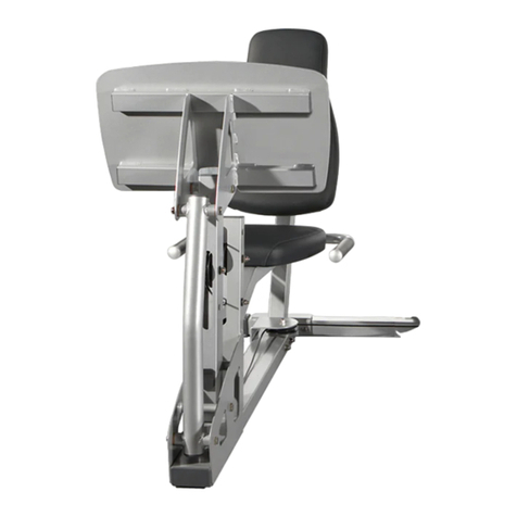
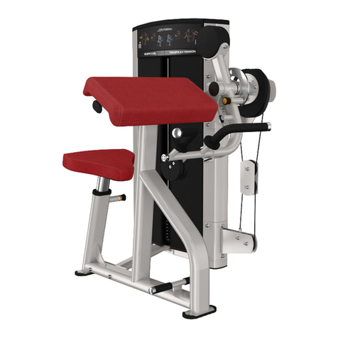
  9. Life Fitness CLUB Series ARM CURL User manual

Life Fitness CLUB Series ARM CURL User manual

Other Life Fitness Fitness Equipment manuals

Life Fitness OPTIMA SERIES User manual

Life Fitness

Life Fitness OPTIMA SERIES User manual

Life Fitness 95X-0XXX-05 User manual

Life Fitness

Life Fitness 95X-0XXX-05 User manual

Life Fitness LF-ARC-LB User manual

Life Fitness

Life Fitness LF-ARC-LB User manual

Life Fitness CT9500 Cross-Trainer Configuration guide

Life Fitness

Life Fitness CT9500 Cross-Trainer Configuration guide

Life Fitness 93X-0XXX-04 User manual

Life Fitness

Life Fitness 93X-0XXX-04 User manual

Life Fitness Lifecycle 6500HR User manual

Life Fitness

Life Fitness Lifecycle 6500HR User manual

Life Fitness FIT SERIES User manual

Life Fitness

Life Fitness FIT SERIES User manual

Life Fitness 95XE ARCTIC SILVER User manual

Life Fitness

Life Fitness 95XE ARCTIC SILVER User manual

Life Fitness CLUB SERIES FLY User manual

Life Fitness

Life Fitness CLUB SERIES FLY User manual

Life Fitness Stepper Machine 90 Series Manual

Life Fitness

Life Fitness Stepper Machine 90 Series Manual

Life Fitness Base X1 User manual

Life Fitness

Life Fitness Base X1 User manual

Life Fitness CLUB TRICEP Series User manual

Life Fitness

Life Fitness CLUB TRICEP Series User manual

Life Fitness Synrgy 180 Personal Use and care manual

Life Fitness

Life Fitness Synrgy 180 Personal Use and care manual

Life Fitness Ab Crunch User manual

Life Fitness

Life Fitness Ab Crunch User manual

Life Fitness Axiom Series User manual

Life Fitness

Life Fitness Axiom Series User manual

Life Fitness G3 User manual

Life Fitness

Life Fitness G3 User manual

Life Fitness X1-XX00-0103 User manual

Life Fitness

Life Fitness X1-XX00-0103 User manual

Life Fitness 9500HR User manual

Life Fitness

Life Fitness 9500HR User manual

Life Fitness CLUB SERIES SHROUD KIT 64 Inch User manual

Life Fitness

Life Fitness CLUB SERIES SHROUD KIT 64 Inch User manual

Life Fitness Base X1 User manual

Life Fitness

Life Fitness Base X1 User manual

Life Fitness 95Xe User manual

Life Fitness

Life Fitness 95Xe User manual

Life Fitness Club Series User manual

Life Fitness

Life Fitness Club Series User manual

Life Fitness Elevation Series Flexstrider User manual

Life Fitness

Life Fitness Elevation Series Flexstrider User manual

Life Fitness Elliptical X5i User manual

Life Fitness

Life Fitness Elliptical X5i User manual

Popular Fitness Equipment manuals by other brands

Revitive Arthritis-Knee user manual

Revitive

Revitive Arthritis-Knee user manual

Domyos BM100 operating instructions

Domyos

Domyos BM100 operating instructions

Movement EDGE PUXADA ALTA Assembly manual

Movement

Movement EDGE PUXADA ALTA Assembly manual

Lifeline LLUWB-BLK owner's manual

Lifeline

Lifeline LLUWB-BLK owner's manual

Precor CW-816 Assembly guide

Precor

Precor CW-816 Assembly guide

Balanced Body Precision Rotator Discs manual

Balanced Body

Balanced Body Precision Rotator Discs manual

G-FITNESS AIR ROWER user manual

G-FITNESS

G-FITNESS AIR ROWER user manual

CAPITAL SPORTS Dominate Edition 10028796 manual

CAPITAL SPORTS

CAPITAL SPORTS Dominate Edition 10028796 manual

Martin System TT4FK user guide

Martin System

Martin System TT4FK user guide

CIRCLE FITNESS E7 owner's manual

CIRCLE FITNESS

CIRCLE FITNESS E7 owner's manual

G-FITNESS TZ-6017 user manual

G-FITNESS

G-FITNESS TZ-6017 user manual

Accelerated Care Plus OMNISTIM FX2 CYCLE/WALK user manual

Accelerated Care Plus

Accelerated Care Plus OMNISTIM FX2 CYCLE/WALK user manual

pedalo 20230165 manual

pedalo

pedalo 20230165 manual

Saebo SaeboStim Pro Instructions for use

Saebo

Saebo SaeboStim Pro Instructions for use

Performance HyperVibe User instructions

Performance

Performance HyperVibe User instructions

Scalamobil S27 Operator's manual

Scalamobil

Scalamobil S27 Operator's manual

Precor Experience Series Service manual

Precor

Precor Experience Series Service manual

FYTTER RedMIUM BENCH BE-T6R manual

FYTTER

FYTTER RedMIUM BENCH BE-T6R manual

manuals.online logo
manuals.online logoBrands
  • About & Mission
  • Contact us
  • Privacy Policy
  • Terms and Conditions

Copyright 2025 Manuals.Online. All Rights Reserved.

CLUB SERIES ARM CURL
Part # 7166301
Rev. B Revision: 10/12/011
ASSEMBLY INSTRUCTIONS
PARTS LIST
KEY PART # DESCRIPTION QTY KEY PART # DESCRIPTION QTY
1 68844xx TOWER 1 15 3102942 3/8 X 3-1/2” BOLT 2
1A 6908401 CABLE 1 16 3102905 3/8 X 3-3/4” BOLT 4
1B 6714901 GUIDE ROD BUSHING 2 17 3202404 3/8 X 3” BUTTON HEAD BOLT 4
1C 6692601 END CAP 3 X 2 3 18 3108406 3/8 X 3/4” FLAT HEAD BOLT 2
1D 3222801 4-1/2 PULLEY 3 19 3102807 3/8” LOW HEIGHT LOCK NUT 20
1E 3102807 3/8 NYLOCK NUT 3 20 3221501 3/8” ACORN NUT 1
1F 6866701 3/8 RH WASHER 4 21 3102514 3/8” SAE WASHER 25
1G 6866601 CAP, BLACK 4 22 3114502 3/8” LOCK WASHER 1
1H 6925801 KEEP CLEAR LABEL 1 23 6866701 3/8” RH WASHER 43
1I 3102933 3/8-16 X 2 BOLT 1 24 3233502 1/2 X 3-1/4” SHOULDER BOLT 1
1J 6480301 3/8 SPACER 4 25 6020601 1/2” FLANGE BEARING 2
1K 3102903 3/8-16 X 2.5 BOLT 2 26 3203501 PILLOW BLOCK 2
1L 3102514 WASHER 3/8 FLAT 2 27 6913801 WEIGHT STACK SELECTOR PIN 1
2 71641xx ARM SUPPORT ASSY 1 28 3108001 WEIGHT STACK CUSHION 2
3 68903xx HANDLE ASSY 1 29 6866601 BLACK RH CAP 4
3A 6912001 HANDLE GRIP 2 30 3222001 1” SHAFT COLLAR 2
4 71646xx PIVOT ARM ASSY 1 31 3116001 1-1/4” RUBBER BUMPER 1
5 68839xx GUIDE ROD SUPPORT 1 32 6714901 GUIDE ROD BUSHING 2
6 68889xx CAM SHROUD 1 33 6912801 ACCORDION SLEEVE 2
7 68909xx COUNTERBALANCE 1 34 6937401 PLACARD LABEL 1
8 71644xx CROSS SUPPORT 1 35 6941301 LANGUAGE PLACARD LABEL 1
9 71650xx SEAT FRAME 1 36 6861902 TOP SHROUD 1
9A 6911002 SEAT ADJ ASSY 1 37 6926901 GUIDE ROD 2
9B 6912202 HINGE ASSY 1 38 6887202 10 LB. WEIGHT PLATE (STD) 15
9C 6897101 ADJUST PLATE 1 39 6888402 15 LB. WEIGHT PLATE (OPT) 5
9D 6897001 ADJUST PLATE 15 POS 1 40 69132xx ARM/CHEST PAD 3
9E 3234301 BOLT 4 41 69131xx SEAT PAD 1
10 68888xx 4 X 18” PLATE 1 42 3230701 STARLOCK WASHER 4
11 6925502 HEAD PLATE 1 43 6971601 WEIGHT STACK LABEL 1
12 3102901 3/8 X 1-1/4” BOLT 8 44 6866602 WHITE RH CAP 39
13 3102903 3/8 X 2-1/2” BOLT 3 OR 6866603 PLATINUM RH CAP 39
14 3102922 3/8 X 2-3/4” BOLT 6
*For all 5 digit part numbers you need to add the color at the end. **Language placard kit comes with Dutch, French,
For shrouds and weldments please use the following codes: German, Poruguese, Spanish, Japaneese, and
xxxxx07 Denotes Platinum Italian.
xxxxx08 Denotes White
*For upholstery, please use the following codes:
CodeDescription
#02ROYAL BLUE
#03SLATE
#04CRANBERRY
#05NORTHWOODS
#06 SPACE BLUE
#07AMERICAN BEAUTY RED
#08SUEDE
#12 BLACK
#13HUNTER GREEN
#14 REGIMENTAL BLUE
#15GINGERSNAP
#16CONCORD
#17URQUOISE
#18 RASPBERRY
#19CROCUS
2"
1C
1G
1E
1F
1J 1
1H
1B
1L
1I
1D
1A
1K
STEP 1:
FIGURE 1
4
0123456
1/2 1/2 1/2 1/2 1/2 1/2
3/8 X 2-3/4” 14
44
21 23
1
44
19
2
• LOOSELY assemble the top of the ARM SUPPORT (2) to the TOWER (1) using four RH CAPS (44), two 3/8 X 2-3/4” BOLTS
(14), four 3/8” SAE WASHERS (21), four 3/8” RH WASHERS (23) and two 3/8” LOW HEIGHT LOCK NUTS (19) as shown in
FIGURE 1.
• LOOSELY assemble the bottom of theARM SUPPORT (2) to the TOWER (1) using four RH CAPS (44), two 3/8 X 3-3/4” BOLTS
(16), four 3/8” SAE WASHERS (21), four 3/8” RH WASHERS (23) and two 3/8” LOW HEIGHT LOCK NUTS (19) as shown in
FIGURE 1.
3/8 X 3-3/4” 16
1A
1B
• LOOSELY assemble the SEAT FRAME (9) to the ARM SUPPORT (2) using four RH CAPS (44), two 3/8 X 3-3/4” BOLTS (16),
four 3/8” SAE WASHERS (21), four 3/8” RH WASHERS (23), and two 3/8” LOW HEIGHT LOCK NUTS (19) as shown in
FIGURE 2.
STEP 2:
FIGURE 2
5
3/8 X 3-3/4” 16
9
19
2
23
21
44
9D
1A
9A
9E
9C
9B
6
0123456
1/2 1/2 1/2 1/2 1/2 1/2
STEP 3:
FIGURE 3
•Securely tighten all loose frame connections made to this point, then proceed to snap RH
CAPS (44) over the RH WASHERS (23) on all tightened connections.
• LOOSELY assemble the CROSS SUPPORT (8) to theARM SUPPORT (2) and SEAT FRAME (9) using seven RH CAPS (44), four
3/8 X 2-3/4 BOLTS (14), seven 3/8” SAE WASHERS (21), seven 3/8” RH WASHERS (23) and three 3/8” LOW HEIGHT LOCK
NUTS (19) as shown in FIGURE 3.
3/8 X 2-3/4” 14
9
8
2
23
44
19
21 9A
9B
7
• Slide two ACCORDION SLEEVES (33) and two PILLOW BLOCKS (26) over the PIVOT ARM (4) as shown in FIGURE 4
STEP 4
FIGURE 4
• SECURELY assemble the PIVOT ARM (4) to the ARM SUPPORT (2) using four previously inserted 3/8 X 3” BUTTON HEAD
CAP SCREWS (17), four RH WASHERS (23), four 3/8” LOW HEIGHT LOCK NUTS (19) and four RH CAPS (44) as shown.
STEP 5:
FIGURE 5
33
26
4
• Assemble one 1-1/4” RUBBER BUMPER (31) to the ARM SUPPORT (2) where the PIVOT ARM (4) shaft contacts tube.
TIGHTEN!
SET SCREWS
3/8 X 3” 17
2
19
44
23
4
31
• IMPORTANT! When PIVOT ARM (4) is centered and level in the PILLOW BLOCKS (26), tighten the PILLOW BLOCK set
screws.
42
17 3/8 X 3”
BUTTON HEAD
• Assemble four 3/8 X 3” BUTTON HEAD CAP SCREWS (17) and four STARLOCK WASHERS (42) to the the PILLOW
BLOCKS (26) as shown in FIGURE 4.
8
0123456
1/2 1/2 1/2 1/2 1/2 1/2
STEP 6:
FIGURE 6
STEP 7:
FIGURE 7
• Assemble the HANDLE (3) to the PIVOT ARM (4) using one 1/2 X 3-1/4” SHOULDER BOLT (24), one 3/8” LOCK WASHER
(22), and one 3/8” ACORN NUT (20) as shown in FIGURE 7. (NOTE: TIghten enough to allow HANDLE to rotate freely.)
• Insert two 1/2” FLANGE BEARINGS (25) into the HANDLE (3) as shown in FIGURE 6.
25
3
24 1/2 X 3-1/4”
22
20
4
3A
9
STEP 8:
FIGURE 8
• SECURELY assemble the COUNTERBALANCE (7) to the PIVOT ARM (4) using two RH CAPS (44), one 3/8 X 2-1/2” BOLT
(13), two 3/8” SAE WASHERS (21), two 3/8” RH WASHERS (23) and one 3/8” LOW HEIGHT LOCK NUT (19) as shown in
FIGURE 8.
STEP 9:
FIGURE 9
• Slide the end of the CABLE into the bushing on the PIVOTARM (4) as shown in FIGURE 9.
13 3/8 X 2-1/2”
23
44
21
7
4
19
4
CABLE
1A
1A
3"
STEP 10:
FIGURE 10
• SECURELY assemble the CHEST/ARM PAD (40) to the SEAT FRAME (9) using two RH CAPS (44), two 3/8 X 1-1/4” BOLTS
(12) and two 3/8” RH WASHERS (23) as shown in FIGURE 10. (Note the the direction of the hole pattern on pad.)
• SECURELY assemble the SEAT PAD (41) to the seat post on the SEAT FRAME (9) using two BLACK RH CAPS (29), two 3/8
X 1-1/4” BOLTS (12) and two 3/8” RH WASHERS (23) as shown in FIGURE 10.
12 3/8 X 1-1/4”
29
9
23
40
41
0123456
1/2 1/2 1/2 1/2 1/2 1/2
10
• SECURELY assemble the CAM SHROUD (6) to the ARM SUPPORT (2) using two RH CAPS (44), two BLACK RH CAPS
(29), two 3/8 X 3-1/2” BOLTS (15), four 3/8” SAE WASHERS (21), four 3/8” RH WASHERS (23) and two 3/8” LOW
HEIGHT LOCK NUTS (19) as shown in FIGURE 10.
3/8 X 3-1/2” 15
29
19
50
23
21
44
50
12 3/8 X 1-1/4”
44 23