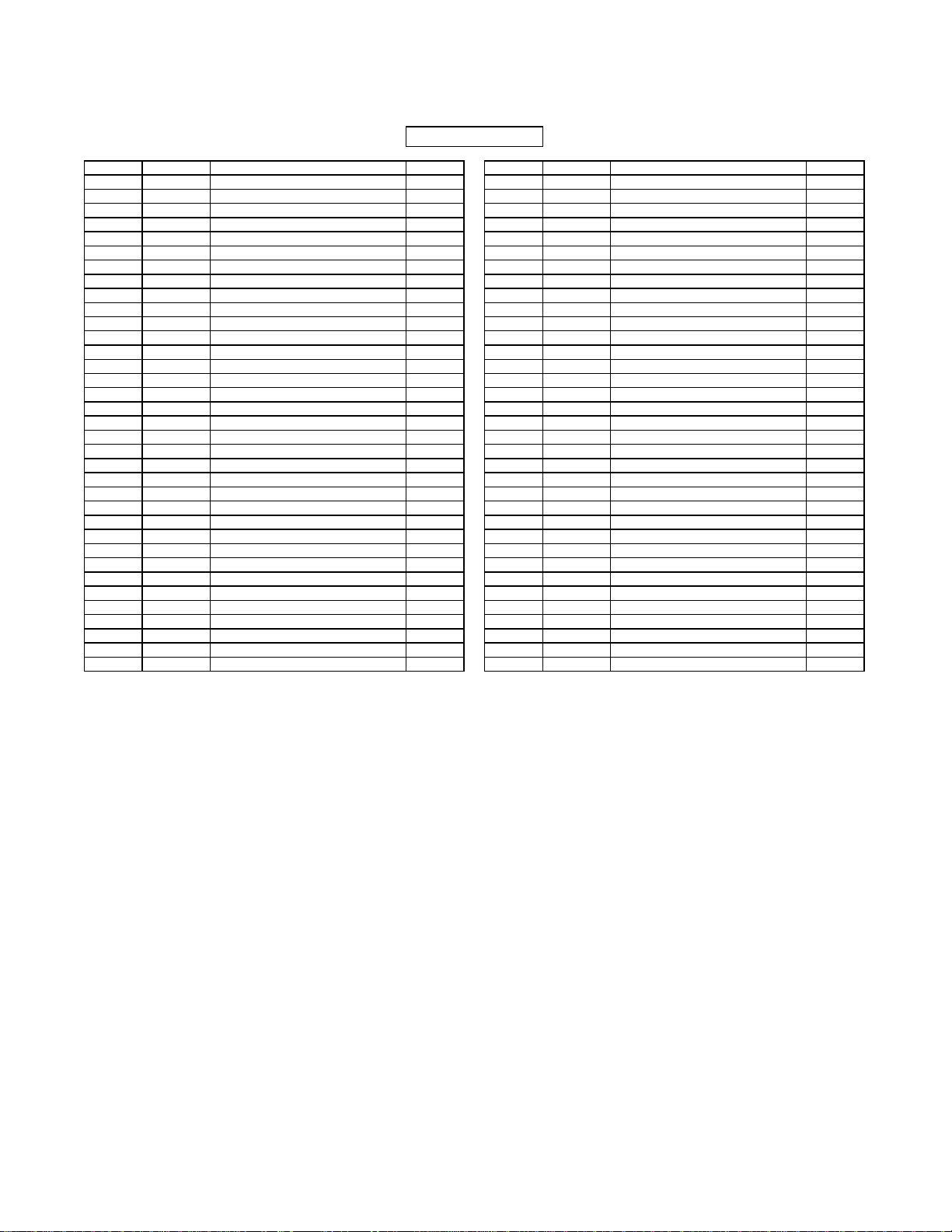
manuals.online logo
Brands
  1. Home
  2. •
  3. Brands
  4. •
  5. Life Fitness
  6. •
  7. Fitness Equipment
  8. •
  9. Life Fitness Club Series User manual

Life Fitness Club Series User manual

CLUB SERIES SEATED ROW
Part # 7160901
RevA. Revision:8/7/011
ASSEMBLY INSTRUCTIONS
PARTS LIST
KEY PART
#
DESCRIPTION QT
Y
KEY PART
#
DESCRIPTION QT
Y
1 70180xx TOWER 1 11 3102933 3/8 X 2” BOLT 4
1A 7024201 CABLE 1 12 6957001 WEIGHT STACK LABEL 1
1B 6692601 END CAP 3 X 2 2 13 3102903 3/8 X 2-1/2” BOLT 2
1C 6866601 CAP, RH-20 BLK 2 14 3102922 3/8 X 2-3/4” BOLT 16
1D 3102933 3/8-16 X 2 BOLT 1 15 3102906 3/8 X 4” BOLT 2
1E 3102514 3/8 FLAT WASHER 2 16 3102940 3/8 X 5” BOLT 2
1F 3222801 4.5" PULLEY 1 17 3202407 3/8 X 3-1/4” BUTTON HEAD BOLT 4
1G 6866701 3/8 RH WASHER 2 18 3102807 3/8” LOW HEIGHT LOCK NUT 28
1H 3102807 3/8-16 NYLOCK NUT LOW HT 1 19 3102514 3/8” SAE WASHER 48
1I 6714901 GUIDE ROD BUSHING 2 20 6866701 3/8” RH WASHER 56
2 70251xx ASSY, MAIN UPRIGHT 1 21 3203501 PILLOW BLOCK 2
2A 6967402 ASSY, SEAT ADJ BLK 1 22 3116001 1-1/4” SQ. RUBBER BUMPER 2
2B 6897001 ADJ PLATE 15 POS 1 23 6913801 WEIGHT STACK SELECTOR PIN 1
2C 6897101 ADJ PLATE 1 24 3108001 WEIGHT STACK CUSHION 2
2D 3234301 5/16-18 X .5 SCREW 4 25 6866601 BLACK RH CAP 4
2E 6912202 HINGE BLK 2 26 69131xx CHEST PAD 1
2F 7025002 ASSY, SEAT ADJ BLK 1 27 68775xx SEAT PAD 1
2G 6897101 ADJ PLATE 1 28 3222001 1” SHAFT COLLAR 2
2H 6897001 ADJ PLATE 15 POS 1 29 6714901 GUIDE ROD BUSHING 2
2I 3234301 5/16-18 X .5 SCREW 4 30 6996001 PLACARD LABEL 1
2J 3102416 2 X 1 END CAP 2 31 6995801 LANGUAGE PLACARD LABEL 1
3 70189xx RIGHT TOWER SUPPORT 1 32 6887202 10 LB. WEIGHT PLATE (STD) 20
3A 7024101 COATED FOOT BOARD 2 33 6888402 15 LB. WEIGHT PLATE (OPT) 10
3B 3108402 6/8-16 X 1.5 BOLT 4 34 6927001 GUIDE ROD 2
3C 6866601 CAP, RH-20 BLK 4 35 3230701 STARLOCK WASHER 4
4 70190xx LEFT TOWER SUPPORT 1 36 6866602 WHITE RH CAPS 50
5 70246xx ASSY, BOOM SUPPORT 1 OR 6866603 PLATINUM RH CAPS 50
6 70247xx ASSY, TOP BOOM 1 37 6861902 TOP COVER SHROUD BLK 1
7 70254xx ASSY, PIVOT ARM 1 38 6862102 FRONT SIDE SHROUDS BLK 2
7A 6912001 RUBBER GRIP 439 7024407 FRONT PLATINUM SHROUD 1
7B 3222801 4.5" PULLEY 1 40 6925202 ASSY, FULL BACK SHROUD 1
7C 6405201 2 SQ END CAP 4 OPTION* 7052602 ASSY, FULL FRONT SHROUD 1
8 69010xx GUIDE ROD SUPPORT 1
9 6923602 HEAD PLATE 1
10 3102901 3/8 X 1-1/4” BOLT 2
*For all 5 digit part numbers you need to add the color at the end. **Language placard kit comes with Dutch, French,
For shrouds and weldments please use the following codes: German, Poruguese, Spanish, Japaneese, and
xxxxx07 Denotes Platinum Italian.
xxxxx08 Denotes White
*For upholstery, please use the following codes:
#02ROYAL BLUE
#03SLATE
#04CRANBERRY
#05NORTHWOODS
#06 SPACE BLUE
#07AMERICAN BEAUTY RED
#08SUEDE
#12 BLACK
#13HUNTER GREEN
#14 REGIMENTAL BLUE
#15GINGERSNAP
#16CONCORD
#17URQUOISE
#18 RASPBERRY
#19CROCUS
1
(2X)
(2X)
(2X) (2X)
(2X)
1C
1D
1E
1B 1H
1G
1F 1A
1I
STEP 1:
FIGURE 1
4
0123456
1/2 1/2 1/2 1/2 1/2 1/2
• LOOSELY assemble the RIGHT and LEFT TOWER SUPPORT (3 & 4) to the TOWER (1) using eight RH CAPS (36), four 3/8
X 2-3/4” BOLTS (14), eight 3/8” SAE WASHERS (19), eight 3/8” RH WASHERS (20) and four 3/8” LOW HEIGHT LOCK
NUTS (18) as shown in FIGURE 1.
1
3
4
3/8 X 2-3/4” 14
19
36
18
20
1A
5
FIGURE 2
STEP 2:
• LOOSELY assemble the MAIN UPRIGHT (2) between the RIGHT and LEFT TOWER SUPPORT (3 & 4) using four RH CAPS
(36), two 3/8 X 4” BOLTS (15), four 3/8” SAE WASHERS (19), four 3/8” RH WASHERS (20) and two 3/8” LOW HEIGHT
LOCK NUTS (18) as shown in FIGURE 2.
15 3/8 X 4”
18
2
20
19
4
36
• Proceed to tighten up the last two connections made, using the following steps:
• Shim up the RIGHT and LEFT TOWER SUPPORTS (3&4) so that they are flush with the PLATES on the TOWER (1)
then SECURELYTIGHTEN. SEE FIGURE 2-B
• Shim up the MAIN UPIRIGHT (2) so that it is flush with the PLATES of the RIGHT and LEFT TOWER SUPPORTS
(3&4) then SECURELY TIGHTEN. SEE FIGURE 2-B
FIGURE 2-B
3 X 2” TUBE
PLATE
FLUSH
FLUSH
FLUSH
FLUSH
1A
2E
3C
2J
2H
2E
2A
2D
3B
3
3A
2I
2G
2F
2C
2B
6
0123456
1/2 1/2 1/2 1/2 1/2 1/2
FIGURE 3
STEP 3:
• LOOSELY assemble the BOOM SUPPORT (5) to the TOWER (1) using eight RH CAPS (36), four 3/8 X 2-3/4” BOLTS (14),
eight 3/8” SAE WASHERS (19), eight 3/8” RH WASHERS (20) and four 3/8” LOW HEIGHT LOCK NUTS (18) as shown in
FIGURE 3.
• LOOSELY assemble the BOOM SUPPORT (5) to the MAIN UPRIGHT (2) using four RH CAPS (36), two 3/8 X 2-3/4” BOLTS
(14), four 3/8” SAE WASHERS (19), four 3/8” RH WASHERS (20) and two 3/8” LOW HEIGHT LOCK NUTS (18) as shown
in FIGURE 3.
14 3/8 X 2-3/4”
3/8 X 2-3/4” 14 20
5
18
19
36
2
1
2E
2A
2F
7
STEP 4:
FIGURE 4
•Securely tighten all loose frame connections made to this point, then proceed to snap RH CAPS
(36) over the RH WASHERS (20) on all tightened connections.
• LOOSELY assemble the TOP BOOM (6) to the TOWER (1) using six RH CAPS (36), two 3/8 X 5” BOLTS (16), two 3/8 X 2-3/
4” BOLTS (14), eight 3/8” SAE WASHERS (19), eight 3/8” RH WASHERS (20) and four 3/8” LOW HEIGHT LOCK NUTS (18)
as shown in FIGURE 4.
• LOOSELY assemble the TOP BOOM (6) to the BOOM SUPPORT (5) using eight RH CAPS (36), four 3/8 X 2-3/4” BOLTS (14),
eight 3/8” SAE WASHERS (19), eight 3/8” RH WASHERS (20) and four 3/8” LOW HEIGHT LOCK NUTS (18) as shown in
FIGURE 4.
3/8 X 2-3/4” 14
3/8 X 5” 16 6
1
36
20
19
5
18
8
0123456
1/2 1/2 1/2 1/2 1/2 1/2
FIGURE 5
STEP 5:
• Slide two PILLOW BLOCKS (21) over the shafts on the PIVOTARM (7) as shown in FIGURE 5.
STEP 6:
FIGURE 6
• IMPORTANT! When PIVOT ARM (7) is centered and level in the PILLOW BLOCKS (21), tighten the PILLOW BLOCK set
screws.
• SECURELY assemble the PILLOW BLOCKS (21) to the TOP BOOM (6) using four 3/8 X 3-1/4” BUTTON HEAD CAP
SCREWS (17), four 3/8” SAE WASHERS (19), four RH WASHERS (20), four 3/8” LOW HEIGHT LOCK NUTS (18) and four
RH CAPS (36) as shown in FIGURE 6
TIGHTEN!
21
7
17 3/8 X 3-1/4”
BUTTONHEAD
BOLT
36
18
20 19
7
21
6
TIGHTEN!
35
17 3/8 X 3-1/4”
BUTTON HEAD
• Assemble four 3/8 X 3-1/4” BUTTON HEAD CAP SCREWS (17) and four STARLOCK WASHERS (35) to the the PILLOW
BLOCKS (21) as shown in FIGURE 5.
7A
7B
7C
STEP 7:
FIGURE 7
• SECURELYassemble the CHESTPAD (26)totheSEATADJUST(2A)usingtwoBLACKRHCAPS(25),two3/8X1-1/4”BOLTS (10)
and two 3/8” RH WASHERS (20) as shown in FIGURE 8.
STEP 8:
FIGURE 8
9
• SECURELYassemble the SEAT PAD (27) to the SEAT ADJUST (2F) using two BLACK RH CAPS (25), two 3/8 X 2” BOLTS (11) and
two3/8” RHWASHERS (20) as shown in FIGURE 7.
11 3/8 X 2”
25
27
2F
20
10 3/8 X 1-1/4”
26
2
25 20
10
0123456
1/2 1/2 1/2 1/2 1/2 1/2
STEP 9:
FIGURE 9
• Insert the two GUIDE RODS (34) (found in SHROUD KIT box) into the base of the TOWER (1) as shown in FIGURE 9. Lubricate
the GUIDE RODS (34) with a silicone or teflon spray that is available at most hardware stores.
• Slide two WEIGHT STACK CUSHIONS (24) down over the GUIDE RODS (34). See FIGURE 9.
• Using EXTREME CARE place twenty 10 LB. WEIGHT PLATES (32) over the GUIDE RODS (34) as shown in FIGURE 9.
(NOTE: If HEAVY WEIGHT OPTION is being used, slide ten 15LB. WEIGHT PLATES (33) over the GUIDE RODS (34)
first, then slide ten 10 LB. WEIGHT PLATES (32) over the GUIDE RODS.)
• Carefully Slide the HEAD PLATE (9) down over the GUIDE RODS (34) onto the weight stack as shown in FIGURE 9.
• Slide one WEIGHT STACK SELECTOR PIN (23) over the shaft on the HEAD PLATE (9) as shown in FIGURE 9.
• Slide two GUIDE ROD BUSHINGS (29) over each GUIDE ROD (34).
• Slide two 1” SHAFT COLLARS (28) over each GUIDE ROD (34) as shown in FIGURE 9.
• Place the GUIDE ROD SUPPORT (8) over the GUIDE RODS (34) as shown in FIGURE 9.
24
32
34
9
23
28
29
8
1
33
HEAVYWEIGHTOPTION
32
1A
11
• Screw the threaded end of the CABLE ALLTHE WAY into the end of the shaft on the HEAD PLATE (9) and tighten jam nut
securely. See FIGURE 10.
STEP10:
FIGURE 10
• SECURELY assemble the GUIDE ROD SUPPORT (8) to the TOWER (1) using four RH CAPS (36), two 3/8 X 2-1/2” BOLTS
(13), four 3/8” RH WASHERS (20) and two 3/8” LOW HEIGHT LOCK NUTS (18) as shown in FIGURE 10.
• Slide GUIDE ROD BUSHINGS (29) into the tubes on the GUIDE ROD SUPPORT (8), slide 1” SHAFT COLLARS (28) under-
neath the GUIDE ROD BUSHINGS (29) and SECURELY tighten the set screws.
• Insert the WEIGHT STACK PIN (23) into the WEIGHT STACK as shown in FIGURE 10.
13 3/8 X 2-1/2”
20
36
8 29 TIGHTEN!
18
1
CABLE
9
23
28
0123456
1/2 1/2 1/2 1/2 1/2 1/2
12
ST``````
FIGURE 11
• Peel the backing off the WEIGHT STACK LABELS (12), line up sheet to the right of the selector opening and apply labels to
the WEIGHT PLATES (32), starting with the HEAD PLATE (9) as shown in FIGURE 11.
12
9
32
• The WEIGHT STACK LABEL sheet (12) includes labels for both lbs. and kgs. for both the standard and optional weight stacks.
13
STEP 12: FIGURE 12
• Swivel PIVOTARM (7) back against the BOOM SUPPORT (5) and assemble the swivel end of the CABLE to the TOP BOOM (6)
using one 3/8 X 2” BOLT (11), two 3/8” SAE WASHERS (19), two RH WASHERS (20), one 3/8” LOW HEIGHT LOCK NUT (18)
and two RH CAPS (25) as shown in FIGURE 12. (NOTE: Allow CABLE swivel end to rotate.)
• Carefully route the CABLE around the pulleys as shown in the CABLE DIAGRAM. Make sure the CABLE is in the grooves of all
the pulleys.
CABLE DIAGRAM
CABLE
• SECURELY assemble one 3/8 X 2” BOLT (11), two RH CAPS (36), two 3/8” RH WASHERS (20), two 3/8” SAE WASHERS (19)
and one 3/8” LOW HEIGHTLOCK NUT (18) to the PIVOTARM (7) as shown in FIGURE 12. (NOTE: Make sure CABLE runs
under the retaining bolt.)
11 3/8 X 2”
19 20
25
18
7
3/8 X 2” 11
18
19
20
36
CABLE
• NOTE: If this machine will be assembled with the FULL FRONT SHROUD, please refer to the SHROUD ASSEMBLY
instructions now. The FULL FRONT SHROUD must be assembled before the CABLE can be routed.)
• Attach two 1-1/4” SQ. RUBBER BUMPERS (22) to the BOOM SUPPORT (5) where the PIVOT ARM (7) makes contact .
6
22
5
FIGURE 13
STEP13:
• Assemble the PLACARD LABEL(30) or the FOREIGN LANGUAGE PLACARD LABEL (31) to the FRONTSHROUD as shown
in FIGURE 13.
31
30
14
• REFER TO SHROUD KIT ASSEMBLY INSTRUCTIONS.
37 38 39
40
Clean:
• Upholstery with mild soap and water.
• Guide rods with a cotton cloth.
• Hand grips with mild soap and water.
• Frame damage can be repaired with touch-up paint purchased from your LifeFitness customer service representative at (800)351-
3737
Inspect:
• Cables for wear or damage and proper tension (should not exceed 3/4” deflection.) Pay close attention at bends and attachment
points.
• Hardware should be checked for looseness. Tighten as required.
• Frames should be inspected for wear or damage.
• Hand Grips should be checked for wear or damage
Lubricate:
• Lube the Guide Rods. Apply the lubricant to a cotton cloth, then run the cotton cloth up and down the guide rods as needed. Do not
spray lubricant directly on the Guide Rods.
PREVENTATIVE MAINTENANCE TIPS
There is a risk assumed by individuals who use this type of equipment. To minimize risk, please
follow these rules:
2. Do not allow minors or children to play on or around this equipment.
1. Inspect equipment daily. Tighten all loose connections and replace worn parts immediately.
Failure to do so may result in serious injury.
3. Exercise with care to avoid injury.
4. Consult your physician before beginning any exercise program.
15
Thank you for purchasing the LifeFitness CLUB SERIES SEATED ROW. If unsure of proper use of
equipment, call your local LifeFitness distributor or call the LifeFitness customer service department at
(800) 351-3737
CAUTION-PLEASE READ
Action DAILY WEEKLY QUARTERLY BI-ANNUALLY AS NEEDED
CLEAN
Upholstery X
Guide Rods X
Hand Grips X
INSPECT
Visual Overall X
Cables X
Hardware X
Frame X
Hand Grips X
LUBRICATE
Guide Rods X
WARRANTYINFORMATION
10 YEARS STRUCTURUAL FRAME
3 YEARS PILLOW BLOCKS, PULLEYS, WEIGHT PLATES AND GUIDE RODS
1 YEAR CABLES
90 DAYS UPHOLSTERY

Other manuals for Club Series

14

Other Life Fitness Fitness Equipment manuals

Life Fitness X9I User manual

Life Fitness

Life Fitness X9I User manual

Life Fitness Lifecycle 9100R User manual

Life Fitness

Life Fitness Lifecycle 9100R User manual

Life Fitness 95XEZ-0XXX-01 User manual

Life Fitness

Life Fitness 95XEZ-0XXX-01 User manual

Life Fitness 93X-0XXX-02 User manual

Life Fitness

Life Fitness 93X-0XXX-02 User manual

Life Fitness CL5XH User manual

Life Fitness

Life Fitness CL5XH User manual

Life Fitness Synrgy 180 Personal Use and care manual

Life Fitness

Life Fitness Synrgy 180 Personal Use and care manual

Life Fitness Synrgy 180 User manual

Life Fitness

Life Fitness Synrgy 180 User manual

Life Fitness 93X-0XXX-01 User manual

Life Fitness

Life Fitness 93X-0XXX-01 User manual

Life Fitness Signature SDR1 User manual

Life Fitness

Life Fitness Signature SDR1 User manual

Life Fitness Axiom Series User manual

Life Fitness

Life Fitness Axiom Series User manual

Life Fitness Row GX User manual

Life Fitness

Life Fitness Row GX User manual

Life Fitness 95SE User manual

Life Fitness

Life Fitness 95SE User manual

Life Fitness G3 User manual

Life Fitness

Life Fitness G3 User manual

Life Fitness 95X Cross-Trainer - Inspire Console User manual

Life Fitness

Life Fitness 95X Cross-Trainer - Inspire Console User manual

Life Fitness Multi-Jungle MJACO User manual

Life Fitness

Life Fitness Multi-Jungle MJACO User manual

Life Fitness Elliptical X5i User manual

Life Fitness

Life Fitness Elliptical X5i User manual

Life Fitness X15 Instructions for use

Life Fitness

Life Fitness X15 Instructions for use

Life Fitness LF-ARC-LB-B1 User manual

Life Fitness

Life Fitness LF-ARC-LB-B1 User manual

Life Fitness Row HX User manual

Life Fitness

Life Fitness Row HX User manual

Life Fitness X9i User manual

Life Fitness

Life Fitness X9i User manual

Life Fitness Stair Climbers LS-5600 User manual

Life Fitness

Life Fitness Stair Climbers LS-5600 User manual

Life Fitness 90S User manual

Life Fitness

Life Fitness 90S User manual

Life Fitness 935i User manual

Life Fitness

Life Fitness 935i User manual

Life Fitness Lifecycle 6500HR User manual

Life Fitness

Life Fitness Lifecycle 6500HR User manual

Popular Fitness Equipment manuals by other brands

Domyos DS 910 manual

Domyos

Domyos DS 910 manual

NordicTrack Revitalize inversion system 2.0 831.14895.1 user manual

NordicTrack

NordicTrack Revitalize inversion system 2.0 831.14895.1 user manual

York Fitness 45065 owner's manual

York Fitness

York Fitness 45065 owner's manual

Stamina Aero Pilates Pro XP556 owner's manual

Stamina

Stamina Aero Pilates Pro XP556 owner's manual

mind alive Oasis Pro Protocol guide

mind alive

mind alive Oasis Pro Protocol guide

Body Solid G2B owner's manual

Body Solid

Body Solid G2B owner's manual

SCIFIT PREM-SEAT-01 user manual

SCIFIT

SCIFIT PREM-SEAT-01 user manual

VIRTUFIT Power Tower Deluxe user manual

VIRTUFIT

VIRTUFIT Power Tower Deluxe user manual

Hoist Fitness F753 owner's manual

Hoist Fitness

Hoist Fitness F753 owner's manual

Gymrex GR-PL350 user manual

Gymrex

Gymrex GR-PL350 user manual

AeroPilates AeroPilates Performer Plus 5002 owner's manual

AeroPilates

AeroPilates AeroPilates Performer Plus 5002 owner's manual

Hang ups Teeter EP-850 owner's manual

Hang ups Teeter

Hang ups Teeter EP-850 owner's manual

Weslo momentum G 3.2 user manual

Weslo

Weslo momentum G 3.2 user manual

DS Produkte 6641 operating instructions

DS Produkte

DS Produkte 6641 operating instructions

BRONZE GYM MV-013 user manual

BRONZE GYM

BRONZE GYM MV-013 user manual

3D innovations magnetraner-er owner's manual

3D innovations

3D innovations magnetraner-er owner's manual

Omega Power Equipment AeroFit MLM-300 owner's manual

Omega Power Equipment

Omega Power Equipment AeroFit MLM-300 owner's manual

SPALDING M7703241 owner's manual

SPALDING

SPALDING M7703241 owner's manual

manuals.online logo
manuals.online logoBrands
  • About & Mission
  • Contact us
  • Privacy Policy
  • Terms and Conditions

Copyright 2025 Manuals.Online. All Rights Reserved.