LifeSafety Power B100 User manual

Connecting the B100 Secondary Power Supply
hRemove all AC and battery power from the FPO system before adding or replacing a B100 board.
hObserve polarity of the DCIN and BR Connections or damage to the system could occur.
Description
The B100 provides an additional voltage in a FlexPower sys-
tem. This voltage can either be accessed directly via the B100's
terminals or through other FlexPower Accessory Boards. The
B100’s input is typically supplied by the B1 buss in the system,
allowing the FPO’s battery set to back up the B100’s output
voltage without the need for a second battery set. Output set-
tings for the B100 include a fixed 12V setting and an adjustable
setting of 5 to 18V. Multiple B100s can be added to a system
for virtually unlimited voltage combinations.
Specifications
Input Voltage 8-25V (Must be at least 3V above
output voltage setting)
Current 3.5A maximum
Standby Current 35mA
Output Voltage 5-18V
Current 4A maximum
(Class 2 Power Limited)
Fuse 7.5A ATM automotive style
Size 4.00" x 2.50" x 1.75"
(102mm x 64mm x 45 mm)
Weight 0.20lb (0.09kg)
Regulatory Information
The equipment discussed within this manual has been tested
to the following standards:
• UL294, UL603, UL864, UL1076, UL1481, UL2044, UL2572
• ULC S318, ULC S319, ULC S527
• CSA C22.2 #107.1
• CSFM Approved
1.3
• z
Mounting the B100 Secondary Power Supply
Mounting of the B100 Board to an enclosure is via the four
snap-in standoffs supplied.
1. Locate the appropriate
mounting holes in the
enclosure and snap
the standoffs into the
holes.
2. Align the board mount-
ing holes with the
standoffs (be sure the PC board is properly oriented)
and snap the board onto the standoffs.
B100
B100 Installation Manual
P03-005 Rev A09
DC IN
DC OUT
BR
DC OUT
BR
DC IN
– OUT +
B100’s output to other accessories
(typically to B2 Buss – ensure no other
voltage sources on this buss)
Input voltage continues to other
accessories (typically to B1 Buss – ensure
no other voltage sources on this buss)
FlexIO continues to other accessories
BR continues to other accessories
BR in from System
FlexIO
in from System DC OUT terminals to
device to be powered
Required Connections
Optional Connections
DC Input from System
(Typically the DC1 output
of an FPO power supply)
IThe DC In, DC Out, and BR terminals run
through the board for daisy chaining and each
terminal set is interchangeable from a functional
standpoint.
Either DC IN may be used, either DC Out may be
used or either BR may be used interchangeably.

B100 INSTALL MANUAL 2
B100 – Secondary Power Supply
1
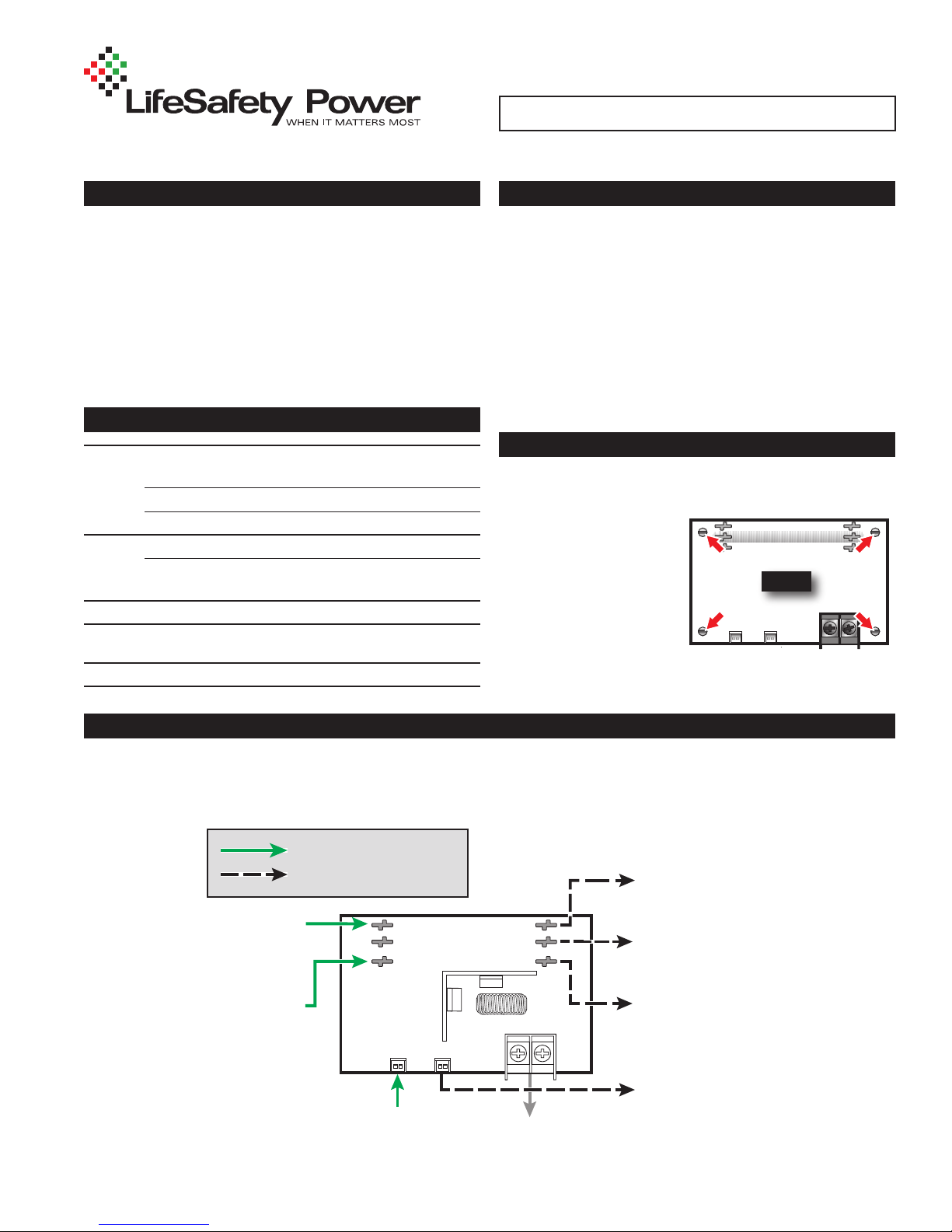
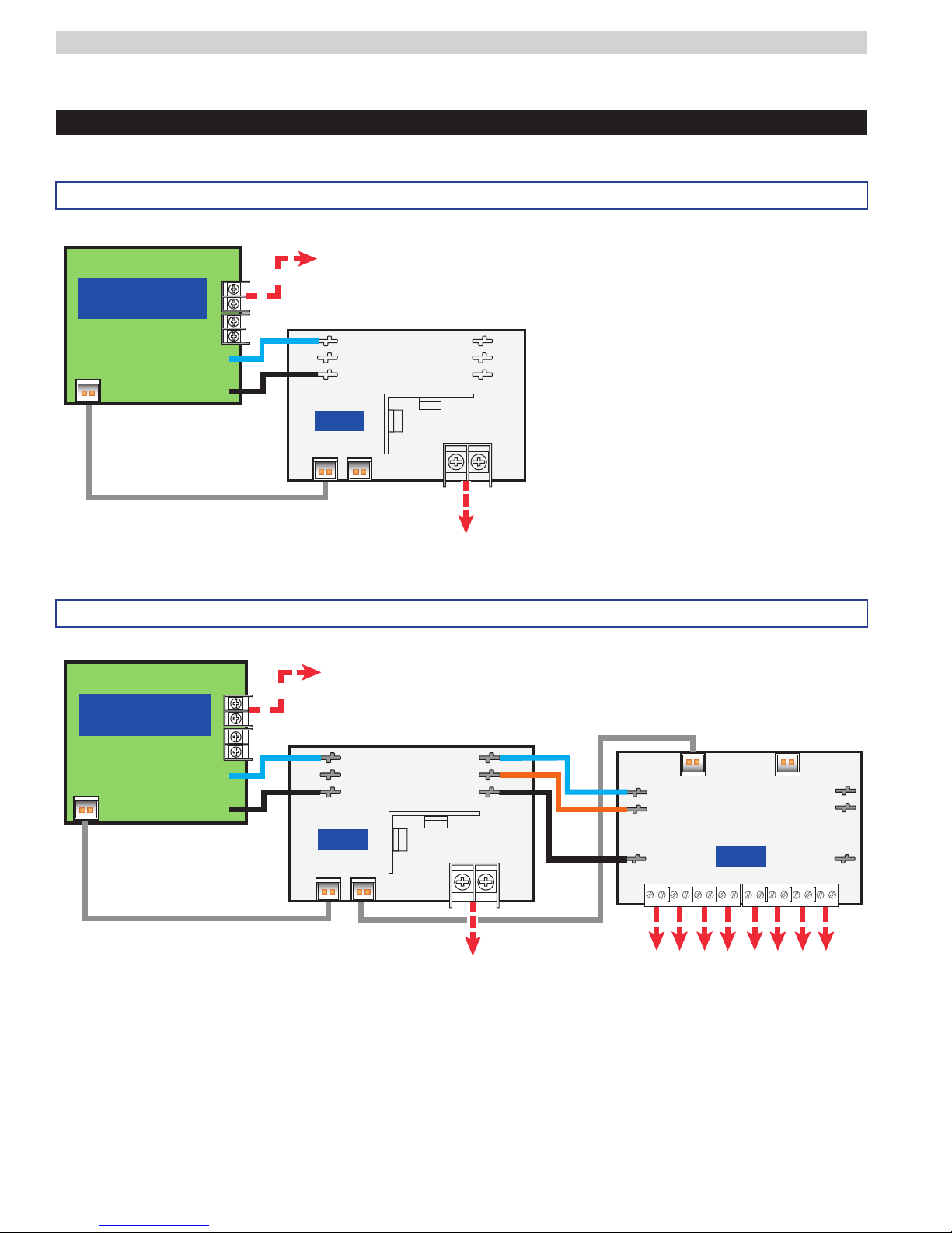
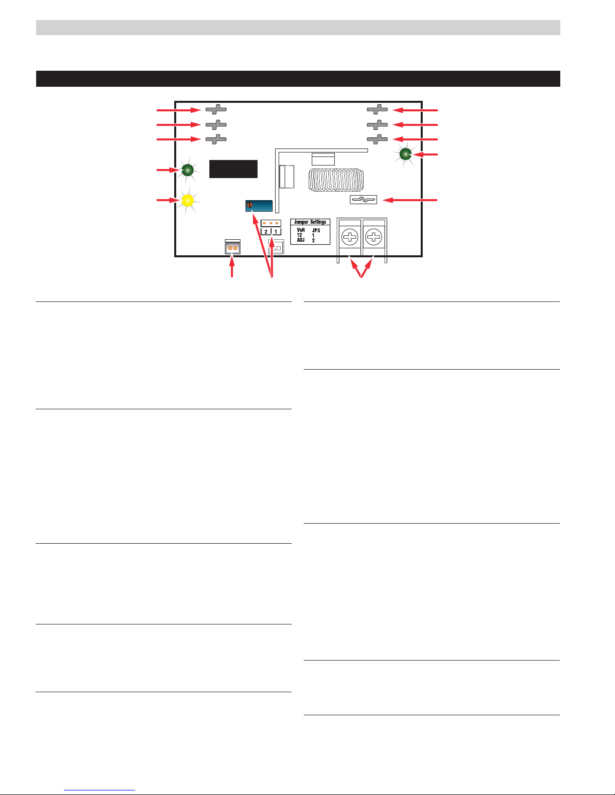
DC IN Connectors (J1 & J4)
These fastons are the input to the B100. Either faston
may be used as the input. Two connections are provided
to allow this voltage to pass through to other accessory
boards in the system. This input voltage must always be at
least 3 volts above the output voltage setting for the B100
to maintain its output.
2
DC OUT Connectors (J2 & J5)
These fastons are the output of the B100 for connection
to other accessories in the system. This output may
be considered as an equivalent to the DC1 faston of an
FPO power supply.
Either or both DC OUT fastons may be used in the system.
IEnsure there are no other voltage sources connected
to the buss before powering the system or damage
WILL occur.
3
BR Connectors (J3 & J6)
The DC Common buss in the system. All boards in the
system must have their BR fastons wired together for
proper operation (except for between the DC and AC
sections of an FPX hybrid system).
4
DC IN LED (D1) – Green
This LED indicates the availability of voltage on the DC
IN Buss. When voltage is available on the buss, the LED
is lit.
5
FAULT LED (D7) – Yellow
This LED lights when the B100 detects a fault condition. This
fault condition also transmits to the FPO power supply
.
Fault conditions detected include ruptured output fuse, no
output, output overload, or output voltage out of regulation.
6
FlexIO Connectors (JP1 & JP2)
These connectors allow the fault status of the B100 to be
transmitted to the FPO power supply and pass the FlexIO
buss on to other accessory boards in the system.
7
Output Voltage Selection (JP3 & VR1)
This jumper selects the output voltage for the B100 and
the potentiometer sets the output voltage when in the
adjustable range. In adjustable range, voltage may be
set from 5 to 18VDC.
Possible jumper settings are as follows:
• 12V Out JP3 Position 1
• Adjustable OutputJP3 Position 2
IThe VR1 potentiometer will have no effect unless
the jumper is set for the adjustable range.
8
DC Output
This is the output terminal strip. This terminal strip is
non-removable and accepts wire sizes from AWG12 –
AWG22. The terminals are labeled on the PC board by
the terminal strip.
ICAUTION When powering magnetic loads such as
maglocks, door strikes, solenoids, etc, each of these
loads must have a reverse protection diode either built-in
or external to the device.
9
Output Fuse (F1)
This fuse protects the DC Output terminals. It does not
protect the DC OUT faston.
bk
DC OUT LED (D4) – Green
This LED indicates the availability of voltage on the DC
OUT Buss. When voltage is available on the buss, the
LED is lit.
B100
DC IN
DC OUT
BR
DC IN
BR
DC OUT
– OUT +
Fault
DC In
DC Out

B100 INSTALL MANUAL 3
B100 Current Loading
Example: 1
An FPO250 set for 24V is powering a B100. The B100 is set for
an output of 12V and has a 3A total load connected.
PO= 12V*3A = 36W
PI= 36W * 1.15 = 41.4W
In this example, the B100 will draw 41.4W from the FPO250
This leaves 208.6W available from the FPO250
Example: 2
What size FPO do I need to create a dual voltage power supply
providing 12V@4A and 24V@6A?
12V x 4A x 1.15 = 55.2 Watts
24V x 6A = 144 Watts
144W + 55.2W = 199.2W
The next greater FPO to 199.2 is 250
Use an FPO250 power supply with the B100 converter
Example: 3
What size FPO do I need to create a dual voltage power supply
providing 12V@1A and 24V@3A?
12V x 1A x 1.15 = 13.8 Watts
24V x 3A = 72 Watts
13.8W + 72W = 85.8W
The next greater FPO to 84 is 150
Use an FPO150 power supply with the B100 converter
Power drawn from the B100 subtracts from the power available from the FPO supplying the B100. The most accurate
way to determine the draw from the FPO is to calculate the actual power draw and factor in the efficiency of the B100.
PI= PO*1.15
Where:
PI= Input power of the B100
PO= Output power draw on the B100
B100 Current Load Examples

B100 INSTALL MANUAL 4
– OUT +
DC IN
BR
DC IN
BR
DC OUT DC OUT
B100
12V OUT
B100 - set to 12V DC
FlexIOFlexIO
FlexIO connectionFlexIO connection
DC1DC1
DC2DC2
BRBR
FPO 24V
24V Out
FlexIOFlexIO
Dual Voltage (24V/12V) using one FPO, one B100
Dual Voltage (24V/12V) using one FPO, one B100 with 8 output distribution
B100 Application Examples
FPO 24V
Each output selectable for
24V (B1) or 12V (B2)
B1
B2
BR
B1
B2
BR
D8
FlexIOFlexIO FlexIOFlexIO
12V OUT
FlexIO connectionFlexIO connection
– OUT +
DC IN
BR
DC IN
BR
DC OUT DC OUT
B100
B100 - set to 12V DC
DC1DC1
DC2DC2
BRBR
FlexIOFlexIO
24V Out
FlexIOFlexIO
FlexIO connectionFlexIO connection

B100 INSTALL MANUAL 5
FPO 24V
– OUT +
DC OUT DC OUT
B100
B100 - set to 5V DC
FlexIOFlexIO
– OUT +
DC IN
BR
DC IN
BR
DC IN
BR
DC IN
BR
DC OUT DC OUT
B100
B100 - set to 12V DC
DC1DC1
DC2DC2
BRBR
FlexIOFlexIO
24V Out
FlexIOFlexIO
FlexIO connectionFlexIO connection
5V OUT
12V OUT
Triple Voltage (24V/12V/5V) using one FPO, two B100's
Triple Voltage (24V/12V/5V) using one FPO, two B100's with 16 output distribution
B100 Application Examples
FlexIO connectionFlexIO connection
5V OUT
Each output selectable for
24V (B1) or 5V (B2)
B1
B2
BR
B1
B2
BR
D8
FlexIOFlexIO FlexIOFlexIO
– OUT +
DC OUT
BR
DC OUT
BR
DC IN DC IN
B100
B100 - set to 5V DC
FlexIOFlexIO
Each output selectable for
24V (B1) or 12V (B2)
B1
B2
BR
B1
B2
BR
D8
FlexIOFlexIO FlexIOFlexIO
12V OUT
FlexIO connectionFlexIO connection
– OUT +
DC IN
BR
DC IN
BR
DC OUT DC OUT
B100
B100 - set to 12V DC
FlexIOFlexIO
FlexIO connectionFlexIO connection
DC1DC1
DC2DC2
BRBR
FPO 24V
24V Out
FlexIOFlexIO

B100 INSTALL MANUAL 6
Each output selectable for
24V (B1) or 12V (B2)
5V OUT
12V Out
DC1DC1
BRBR
FlexIOFlexIO
B1
B2
BR
B1
B2
BR
D8
FlexIO connectionFlexIO connection FlexIO connectionFlexIO connection
FlexIOFlexIO FlexIOFlexIO
– OUT +
DC OUT
BR
DC OUT
BR
DC IN DC IN
B100
B100 - set to 5V DC
DC1DC1
DC2DC2
DC2DC2
BRBR
FPO 24V
FPO 12V
FlexIOFlexIO
FlexIO connectionFlexIO connection
24V Out
FlexIOFlexIO
B100 Application Examples
Triple Voltage (24V/12V/5V) using two FPO's, one B100 with 8 output distribution

B100 INSTALL MANUAL 7
FlexPower System Replacement Parts
Board Kits Order # Description
FPO250 A01-007 FPO250 replacement board
FPO150 A01-005 FPO150 replacement board
FPO75 A01-003 FPO75 replacement board
B100 A03-009 DC-DC Converter (12VDC or adjustable 5 to 18VDC) replacement board
D8 A02-001 Simple distribution replacement board
D8P A02-002 Simple distribution (Class 2) replacement board
F8 A02-003 FAI controlled distribution replacement board
F8P A02-004 FAI controlled distribution (Class 2) replacement board
C4 A02-005 Four zone power control replacement board
C4P A02-006 Four zone power control (Class 2) replacement board
C8 A02-007 Eight zone power control replacement board
C8P A02-008 Eight zone power control (Class 2) replacement board
M8 A02-011 Eight zone managed power control replacement board
M8P A02-012 Eight zone managed power control (Class 2) replacement board
N24 A04-001 Two Input, 4 Output NAC Expander accessory replacement board
NL2 A11-007 Two Port NetLink network communication board (used in FPO systems)
NL4 A11-004 Four Port NetLink network communication board (used in FPO systems)
NLR A11-002 NetLink network communication kit / remote reset (used in FPA systems)
NS2 A11-003 Reset module board for use with NL2
RB2 A25-001 2A Relay, 12VDC or 24VDC input range, DP/DT
RB5 A25-002 5A Relay, 12VDC or 24VDC input range, DP/DT
RB8 A25-003 8A Relay, 12VDC or 24VDC input range, DP/DT
Hardware Order # Description
DL1 A05-001 DataLink USB cable
BDM A05-006 Battery Disconnect Module cable
AC Cable A05-005 AC Input Cable for FPO Power Supply
Battery Cable A05-002 Battery Harness – 24"
Module Cable - 12" A05-003 Accessory board cable set – 12"
Module Cable - 18" A05-004 Accessory board cable set – 18"
Fuse - 3A A05-201 ATM-3A Fuse – Bag of 25
Fuse - 5A A05-202 ATM-5A Fuse – Bag of 25
Fuse - 7.5A A05-203 ATM-7.5A Fuse – Bag of 25
Fuse - 10A A05-204 ATM-10A Fuse – Bag of 25
Fuse - 15A A05-205 ATM-15A Fuse – Bag of 25
Fuse - 30A A05-206 ATM-30A Fuse – Bag of 25
Standoffs A05-301 Nylon Standoffs – Bag of 25
Camlock Set A05-302 Key and Lock fits LSP "E" enclosure

LifeSafety Power Inc.
750 Tower Road, Unit B
Mundelein, IL 60060 USA
www.lifesafetypower.com
Tel (888) 577-2898
info@lifesafetypower.com
Important: All information, including illustrations, is believed to be reliable. Users, however, should independently evaluate
the suitability of each product for their particular application. LifeSafety Power makes no warranties as to the accuracy or
completeness of the information, and disclaims any liability regarding its use. LifeSafety Power’s only obligations are those
in the LifeSafety Power Standard Terms and Conditions of Sale for this product, and in no case will LifeSafety Power or its
distributors be liable for any incidental, indirect, or consequential damages arising from the sale, resale, use, or misuse of
the product. Specifications are subject to change without notice. In addition, LifeSafety Power reserves the right to make
changes—without notification to Buyer—to processing or materials that do not affect compliance with any applicable specification.
LifeSafety Power, FlexConnect and FlexIO are trademarks of LifeSafety Power Inc. or its affiliates.
B100 INSTALL MANUAL 8
© 2015 LifeSafety Power Inc.P03-005 Rev A09 12/15
This manual suits for next models
1
Other LifeSafety Power Power Supply manuals

LifeSafety Power
LifeSafety Power Helix RH150 Series User manual

LifeSafety Power
LifeSafety Power FLEXPOWER iSCAN RS Series User manual

LifeSafety Power
LifeSafety Power FlexPower RA150 Series User manual

LifeSafety Power
LifeSafety Power FlexPower Vantage R8 series User manual

LifeSafety Power
LifeSafety Power FLEXPOWER RC75 Series User manual

LifeSafety Power
LifeSafety Power FlexPower Vantage FPV4 User manual

LifeSafety Power
LifeSafety Power FlexPower User manual

LifeSafety Power
LifeSafety Power FlexPower Generation 2 User manual

LifeSafety Power
LifeSafety Power Helix User manual

LifeSafety Power
LifeSafety Power FlexPower User manual