LifeSafety Power Helix User manual

C4/C4P, C8/C8P Installation Manual
LifeSafety Power, Inc. | PH 888.577.2898 | TechSupport@LifeSafetyPower.com
P03-046 Rev A05
HELIX DC Wallmount
Installation / Operation Manual
REDUNDANT DC
PS
primary
PS
backup
AC primary
HELIX MISSION CRITICAL POWER
REDUNDANT
FAULT
NOTIFICATION
HARDWIRE
WIRE
/
EMAIL
/
SNMP
™

Helix Redundant Power Installation Manual
2 3
Description
The LifeSafety Power Helix line of power supplies are a re-
dundant power source for use in the Access Control industry.
Two identical FPO power supplies are combined in a single
enclosure with the Helix module to provide a single output
voltage. In the event of a failure of the main power source,
the Helix module will automatically switch the output to the
backup FPO power supply. The Helix line of power supplies
are available in Wall and Rack Mount.
Regulatory Information
The equipment discussed within this manual has been tested
to the following standards:
• UL294, UL603, UL1076
• ULC S318 / ULC S319 / CSA C22.2 #205
FlexPower Helix Supplement
Limitations
Due to the nature of this product and its intended applications, the limitations and conditions of installation of the Helix
power supply must be fully understood by the system planner & installer. Please thoroughly read and understand the
following sections before using the Helix power supply.
Redundancy
The Helix line of power supplies adds a layer of redundancy over the typical FPO power supply. Only the FPO power supply is
redundant - any distribution in the system is not redundant. Also, the Helix cannot overcome any problems in the field wiring
or load devices - if a short circuit shuts down the main supply, the backup supply will also be shut down by this short circuit.
Primary AC Connection
Both FPO power supplies must be powered from the same AC branch circuit. Powering the two internal FPO power supplies
from different branch circuits could lead to possible improper operation and loss of output voltage.
Backup Battery
FPO2 must have battery backup connected for proper operation. A battery should not be connected to FPO1 - this is to prevent
cycling between FPO1 and FPO2 during battery discharge on loss of AC.
Fault Contacts
The fault contacts of BOTH FPO power supplies must be monitored to annunciate failure of either power supply. The fault con-
tacts may either be monitored separately or series/paralleled as needed for a common fault indication. Use of a Netlink network
monitoring module is also highly recommended.
I Important information - READ FIRST and in
conjunction with FLEXPOWER Power Supply Manual

Helix Redundant Power Installation Manual
2 3
Installation
Mounting of the board to an enclosure is via the four
snap-in standoffs supplied.
1. Locate the appropriate mounting holes in the
enclosure and snap the standoffs into the holes.
2. Align the board mounting holes with the standoffs
(be sure the PC board is properly oriented) and snap the
board onto the standoffs.
HLX
Limitations - continued
Internal Configuration
All Rack Mount Helix power supplies come fully pre-configured from the factory and should not be changed. Wall Mount Helix
power supplies only require the output voltage and 120/230VAC input jumpers to be configured by the installer. Both FPO power
supplies must be set to the same output voltage for proper operation. Do not rewire or reconfigure any other portion of the Helix
power supply.
FAI
The Helix allows for FAI operation only via accessory boards that provide their own FAI control. The DC2 output of the FPO power
supplies must not be used. Note that if FPO1 is still operational and FPO2 completely fails (power supply and battery backup),
FAI could be activated on any accessory boards within the Helix system, shutting down any FAI enabled outputs.
IThe Fire Alarm Interface (FAI) must be triggered with a NO open relay configuration to avoid a false positive visual indication
under certain conditions. The FAI input of BOTH FPO power supplies must be wired for proper operation under all condi-
tions. For a NO FAI input, parallel the I+ and I- terminals between the two FPO power supplies.

Helix Redundant Power Installation Manual
4 5
FPO1
Helix
Load
FPO1
Vout 1
AC Input
AC Input
Vout 2
Vout
DC1
+
–+
–
FPO2
+
–
FPO2
FPO1
DC1
+
–
DC1
Figure 1: Redundant power supply system wiring with Helix board
+
–
Internal Wiring
Figure 1 shows the internal wiring configuration of the two FPO power supplies and the Helix module. Verify that both FPO
power supplies are set to the same output voltage. The DC1 outputs of FPO1 and FPO2 are connected to the FPO1 and FPO2
inputs of the Helix module, respectively (observe proper polarity). The DC1 and V+/- quick disconnect terminals and the DC
terminal block are electrically the same point and provide the redundant power output to the loads or any accessory boards. Do
not connect any load directly to either FPO power supply in the Helix system - all load connections should be made at or after
the Helix module.

Helix Redundant Power Installation Manual
4 5
Wall Mount Field Wiring Connections
IThe illustration in this section depicts a Helix system using two FPO75 power supplies. Connections and configuration are
the same for Helix systems using different FPO models - consult the FPO power supply manual for locations of the noted items.
The layout of other Helix systems may be different than shown.
Battery
+
–
+
–
FPO1
FPO75
FPO2
FPO75

Helix Redundant Power Installation Manual
6 7
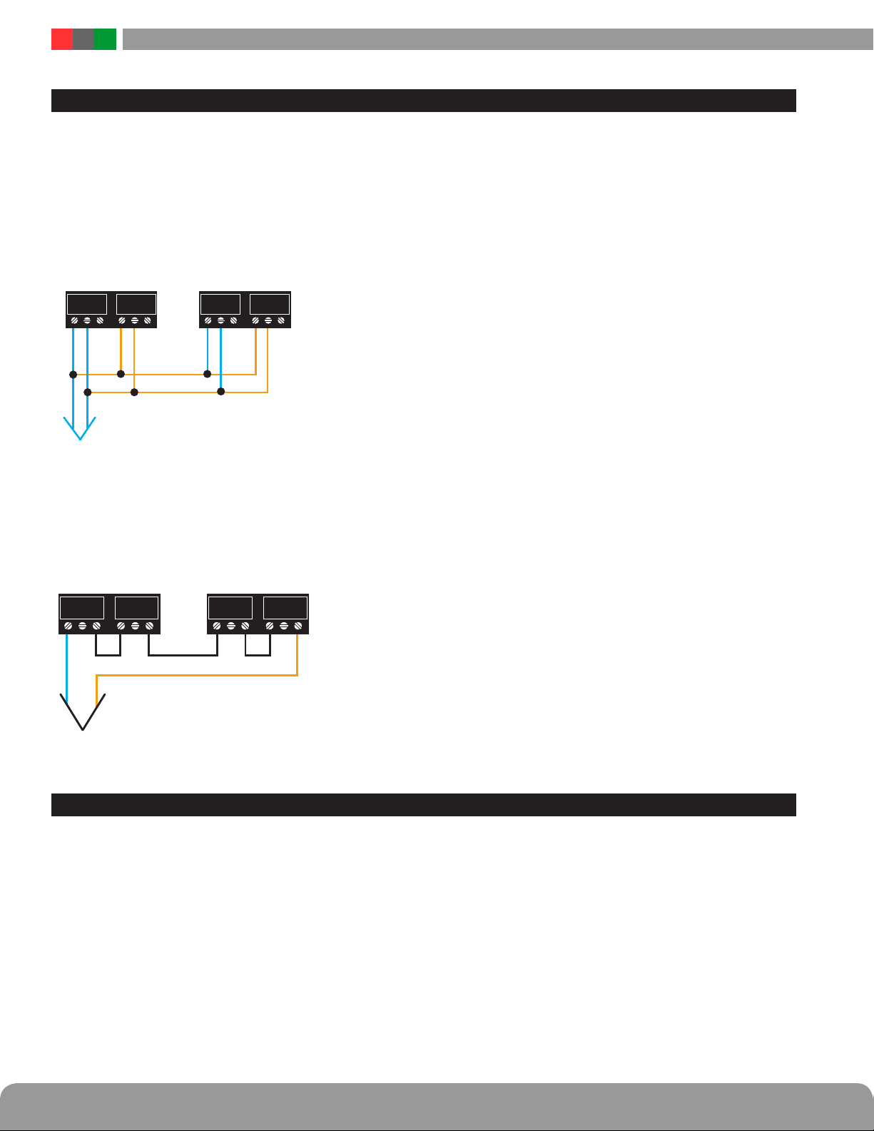
Wall Mount Field Wiring Connections - continued
1FPO1 AC Power Connection - This is the AC input for FPO
power supply #1. See the FPO manual for more information.
It must be connected to the same branch circuit as FPO2.
2FPO1 Fault Outputs - These fault connections must be
monitored along with the fault outputs of FPO2 to ensure
notification of problems with either FPO power supply. See
the FPO manual for more information.
3FPO1 FAI Input - If FAI is required in the system, make the
connection to the FAI terminals of both FPO power supplies.
IThe Fire Alarm Interface (FAI) must be triggered with a NO
open relay configuration to avoid a false positive visual indica-
tion under certain conditions. See the FPO manual for more
information and for wiring information.
4FPO1 Output Voltage Selection - Selects a 12V or 24V
output for FPO1. FPO2 must be set for the same output
voltage. See the FPO manual for more information.
IRemove all power before changing the output voltage or
damage to the system could occur
5FPO1 Battery Connection - Do not connect a back-
up battery to FPO1. The backup battery set should be
connected to FPO2.
6FPO2 AC Power Connection - This is the AC input for FPO
power supply #2. See the FPO manual for more information.
It must be connected to the same branch circuit as FPO1.
7FPO2 Fault Outputs - These fault connections must be
monitored along with the fault outputs of FPO1 to ensure
notification of problems with either FPO power supply. See
the FPO manual for more information.
8FPO2 FAI Input - If FAI is required in the system, make the
connection to the FAI terminals of both FPO power supplies.
IThe Fire Alarm Interface (FAI) must be triggered with a NO
open relay configuration to avoid a false positive visual indica-
tion under certain conditions. See the FPO manual for more
information and for wiring information.
9FPO2 Output Voltage Selection - Selects a 12V or 24V
output for FPO2. FPO1 must be set for the same output
voltage. See the FPO manual for more information.
IRemove all power before changing the output voltage or
damage to the system could occur.
bkFPO2 Battery Connection - A backup battery set (not
included) must be connected to FPO2 for proper operation
of the Helix power supply. The voltage and AH capacity
must be selected appropriately for the application. See the
FPO manual for more information.
blHelix DC +/- This terminal block provides the redundant
power output from the two FPO power supplies. This is a
redundant equivalent of the DC1 output terminals on a typi-
cal FPO power supply.
bmHelix V+/- These quick disconnect terminals provide
redundant output voltage for powering a Netlink network
monitoring module.
bn Helix DC1 +/- These quick disconnect terminals provide
redundant output voltage for powering any accessory boards
in the Helix system. These are a redundant equivalent of the
DC1 quick disconnect terminals on a typical FPO power
supply.
boHelix Status LED - This LED indicates the current status
of the Helix board
Steady Green System OK, Running on FPO1
Steady Yellow Problem with FPO1, Running on FPO2
Flashing Yellow Helix Fault - See Helix Faults section of this
manual for more information
bpHelix Audible Sounder - This sounder will sound a pulsing
alert when the Helix detects a fault condition. See the Helix
Faults section of this manual for more information.
.

Helix Redundant Power Installation Manual
6 7
Rack Mount Field Wiring Connections
IRack Mount Helix models are pre-configured for AC Input and DC Output voltage. All models are single voltage and, although
FAI Inputs are present, FAI control is not available.

Helix Redundant Power Installation Manual
8 9
Rack Mount Field Wiring Connections - continued
1Main AC Power Switch / Circuit Breaker - This is the
main AC power switch for the enclosure. This switch lights
when power is on and also has a built-in circuit breaker
rated at 8A. If the circuit breaker trips, reset it by cycling
the switch to off then back to on.
2AC Line Input - This is the connector for the AC line
cord. Plug the included computer-style line cord into this
connector. Connect the other end of the cord to the power
strip inside the rack or another suitable AC power receptacle.
IRack Mount Helix models are preconfigured for either
120VAC or 230VAC input - Verify the input voltage for the
model being installed prior to applying AC power.
3Ethernet Connection (Optional) - This is the RJ45 jack
for the network connection for the inter¬nal NetLink board
(if present). The ethernet cable is plugged into this jack.
This jack is only present on Helix series power supplies with
a model number ending in "N". See the corresponding Net-
Link manual for more information.
4Distributed Outputs - These are the redundant zone
outputs. The Helix Series is available with 8 or 16 outputs.
The output numbers correspond with the output zone num-
bers on the front panel. Bulk Output models without distri-
bution will not have these terminals.
IRack Mount Helix models are preconfigured for either
12VDC or 24VDC output - Verify the output voltage for
the model being installed prior to connecting field wiring.
5Power Supply Connections - These are the connections
to the internal FPO Power Supplies. Only the following con-
nections should be made - leave all other terminals discon-
nected:
Power Supply 1
ACF & SF - These are the AC and System Fault outputs for
FPO1. From the factory these are set to provide a closed
connection when there is no fault. These fault connections
must be monitored along with the fault outputs of FPO2 to
ensure notification of problems with either FPO power supply.
Power Supply 2
Bat (±) - This is where the battery connection is made. The
voltage of the battery set must match the voltage of the
Helix model being installed. Do not connect a battery to the
Bat +/- terminals of Power Supply 1.
ACF & SF -These are the AC and System Fault out¬puts for
FPO2. From the factory these are set to provide a closed
connection when there is no fault. These fault connections
must be monitored along with the fault outputs of FPO1
to ensure notification of problems with either FPO power
supply.

Helix Redundant Power Installation Manual
8 9
Fault Output Connections
In order to monitor both FPO power supplies for problems, it is imperative that AC and System Fault contacts on both FPO power
supplies be monitored. They may either be monitored separately or commoned into one or two outputs.
For this application, simply wire all four
relay connections separately as needed
For this application, parallel the NC fault
contacts for the Sys Fault and also for the
AC Fault
For this application, series connect the NO
fault contacts for the Sys Fault and also
for the AC Fault
SYS FLT AC FLTSYS FLT AC FLT
FPO1
SYS FLT
FPO1
SYS FLT
FPO1
AC FLT
FPO1
AC FLT
FPO1FPO1
CC NCNC NONO CC NCNC NONO
SYS FLT AC FLTSYS FLT AC FLT
FPO2
SYS FLT
FPO2
SYS FLT
FPO2
AC FLT
FPO2
AC FLT
FPO2FPO2
CC NCNC NONO CC NCNC NONO
SYS FLTSYS FLT AC FLTAC FLT
SYS FLT AC FLTSYS FLT AC FLT
FPO1FPO1
CC NCNC NONO CC NCNC NONO
SYS FLT AC FLTSYS FLT AC FLT
FPO2FPO2
CC NCNC NONO CC NCNC NONO
AC FLTAC FLT
SYS FLT AC FLTSYS FLT AC FLT
FPO1FPO1
CC NCNC NONO CC NCNC NONO
SYS FLTSYS FLT
SYS FLT AC FLTSYS FLT AC FLT
FPO2FPO2
CC NCNC NONO CC NCNC NONO
Seperate Outputs
Common System Fault, Common AC Fault (Contacts CLOSE on fault)
Common System Fault, Common AC Fault (Contacts OPEN on fault)

Helix Redundant Power Installation Manual
10 11
For this application, parallel all NC fault
contacts
For this application, series connect all NO
fault contacts
Fault Output Connections - continued
In order to monitor both FPO power supplies for problems, it is imperative that AC and System Fault contacts on both FPO power
supplies be monitored. They may either be monitored separately or commoned into one or two outputs.
AC &
SYS FLT
AC &
SYS FLT
SYS FLT AC FLTSYS FLT AC FLT
FPO1FPO1
CC NCNC NONO CC NCNC NONO
SYS FLT AC FLTSYS FLT AC FLT
FPO2FPO2
CC NCNC NONO CC NCNC NONO
AC &
SYS FLT
AC &
SYS FLT
SYS FLT AC FLTSYS FLT AC FLT
FPO1FPO1
CC NCNC NONO CC NCNC NONO
SYS FLT AC FLTSYS FLT AC FLT
FPO2FPO2
CC NCNC NONO CC NCNC NONO
Single Fault Output (Contacts CLOSE on fault)
Single Fault Output (Contacts OPEN on fault)
Veryfing System Operation
To verify system operation, power the system and connect the battery to FPO2. Measure the Helix voltage at the DC+/- terminals.
Remove the AC connector from FPO1 while continuing to monitor the Helix voltage. Verify that the voltage remains the same
before, during, and after transfer to FPO2.

Helix Redundant Power Installation Manual
10 11
Helix Audible Alarms
The Helix board has an audible alarm that will sound on various fault conditions that require immediate attention to
maintain redundancy.
The fault conditions include:
• The two FPO boards connected are not set to the same output voltage (i.e. one supply set for a 12V Output and the other set for 24V)
• The output voltage of the backup FPO power supply has gone out of range (high or low)
• The output voltage of both FPO power supplies is abnormal
• Improper power up. One FPO power supply was powered before the other.
• Bad FPO power supply or other internal problem - Contact LifeSafety Power

Helix Redundant Power Installation Manual
12 PB
Section
IMPORTANT
All information, including illustrations, is believed to be reliable. Users, however, should independently evaluate the suitability of each
product for their particular application. LifeSafety Power makes no warranties as to the accuracy or completeness of the information,
and disclaims any liability regarding its use. LifeSafety Power’s only obligations are those in the LifeSafety Power Standard Terms
and Conditions of Sale for this product, and in no case will LifeSafety Power or its distributors be liable for any incidental, indirect, or
consequential damages arising from the sale, resale, use, or misuse of the product. Specifications are subject to change without notice.
In addition, LifeSafety Power reserves the right to make changes—without notification to Buyer—to processing or materials that do not
aect compliance with any applicable specification.
LifeSafety Power Inc.
899 E. Park Avenue
Libertyville, IL 60048 USA
www.lifesafetypower.com
Phone (888) 577-2898
info1@lifesafetypower.com
© 2019 LifeSafety Power, Inc.All rights reservedP03-046 Rev A05 07/19
Table of contents
Other LifeSafety Power Power Supply manuals

LifeSafety Power
LifeSafety Power B100 User manual

LifeSafety Power
LifeSafety Power FLEXPOWER iSCAN RS Series User manual

LifeSafety Power
LifeSafety Power Helix RH150 Series User manual

LifeSafety Power
LifeSafety Power FlexPower Generation 2 User manual

LifeSafety Power
LifeSafety Power FlexPower User manual

LifeSafety Power
LifeSafety Power FlexPower Vantage R8 series User manual

LifeSafety Power
LifeSafety Power FlexPower Vantage FPV4 User manual

LifeSafety Power
LifeSafety Power FlexPower RA150 Series User manual

LifeSafety Power
LifeSafety Power FlexPower User manual

LifeSafety Power
LifeSafety Power FLEXPOWER RC75 Series User manual