RS Series Rackmount Installation Manual
6 7
Installation and Operation
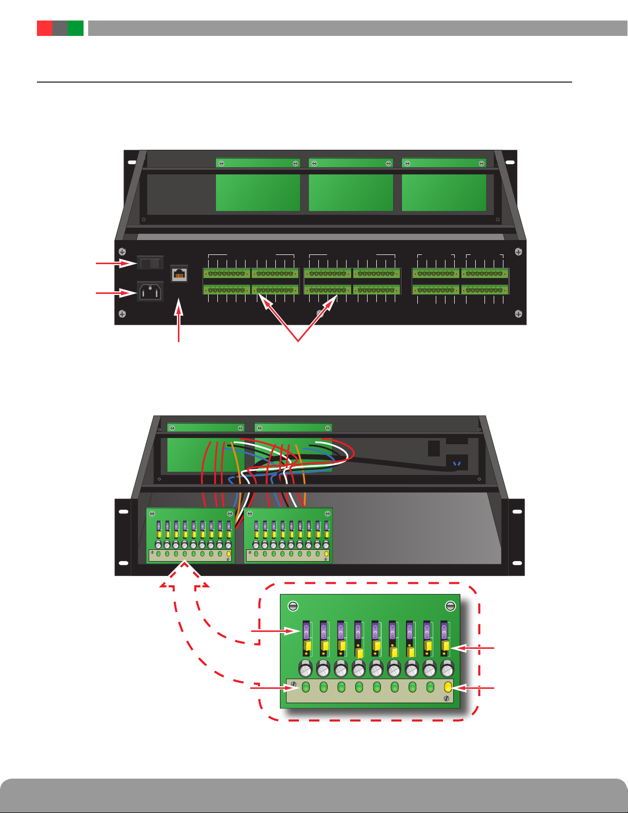
Field wiring connections are made on the rear panel after in-
stalling the iSCAN enclosure into the rack. Field wiring connec-
tions are made to the removable terminal strips, which accept
AWG 12-22 wire. The back panel is also where the main AC
power and optional ethernet connections are made.
1.4.1 Field Wiring
The ISCAN Rackmount series has terminals for various inputs
and outputs as follows:
Controlled Outputs
These terminals provide the distributed, controlled outputs
to the load devices. Depending on model, there will be either
8 or 16 output zones. The output zone numbers will cor-
respond with the the numbering of the zones on the front
panel. Polarity is indicated adjacent to each terminal. The
output is configured using the PowerCom browser interface.
Control Inputs
These are the zone input terminal strips. The terminals are
labeled on the back panel near the terminal strip.
• When using a dry contact input, the contact is connected
across the A and B terminals. When configured for a dry
contact input, it is normal to measure a voltage across these
two terminals. This voltage is current limited and will not
damage the activation contact.
• When using a voltage input, the voltage is connected to the
B terminal. The activation voltage must be common ground-
ed with the system voltage. The activation voltage must be
between 12 and 24VDC nominal. Do not connect anything to
the A terminal of the input.
• When using an open collector (transistor) input, place a
jumper across the A and B terminals and connect the open
collector to the B terminal. Note that the input source must
be common grounded with the iSCAN’s power source.
Distributed Outputs (optional)
If present, these terminals provide the non-controlled dis-
tributed outputs. The output zone numbers will correspond
with the numbering of the zones on the front panel. Polarity
is indicated adjacent to each terminal.
Battery (Bat+, Bat–)
This pair of terminals is for connection to a backup battery
set, if required for the installation. Polarity is noted adjacent
to the terminals. These terminals also charge the battery set.
NOTE: Observe polarity or damage to the system will occur.
Ensure the voltage of the battery set matches the voltage of
the power supply.
NOTE: It is the installer's responsibility to determine the
proper battery size for the installation. See the Specifications
section for battery standby current requirements.
DC1+, DC1–
The main DC output of the FPO power supply. The full cur-
rent of the FPO is available on these terminals at all times
and is unaffected by the FAI input.
DC2+, DC2–
The DC2 output may optionally be controlled by the FAI in-
put. The full current of the FPO is available on these termi-
nals. The DC2 output may be set to power up when an FAI
signal is received or to drop power when an FAI signal is
received by changing the position of the DC2 fuse on the
FPO before installing the ISCAN RM into the rack.
AC Fault (ACF)
These terminals provide the AC Fault relay output from the
FPO power supply. This relay signals when the internal FPO
power supply detects a low or missing AC input voltage.
From the factory this output is set to provide a CLOSED
connection when there is no fault. During a fault condition,
the connection between these terminals will OPEN. To re-
verse this operation, see Section 1.3.5 of this manual.
System Fault (SF)
These terminals provide the System Fault relay output from
the FPO power supply. This relay signals when any of the
following conditions occur:
• Missing Battery (If BAT DET jumper is ON)
• Earth Ground Fault (If EARTH GND DET jumper is ON)
• Battery voltage out of range
• DC output voltage out of range
• Ruptured fuse
• Accessory Board Fault
• Internal Fault
From the factory this output is set to provide a CLOSED
connection when there is no fault. During a fault condition,
the connection between these terminals will OPEN.To re-
verse this operation, see Section 1.3.5 of this manual.
FAI Input (V+, I+, I–, V–, L, L)
These terminals accept the optional FAI / Access Control in-
put for controlling the DC2 output. See Figure 4 - FAI Input
Usage for more information. Connections are as follows:
• L Terminals Latch Reset contact input. If a latching FAI Input
is desired, a normally closed contact is placed across these
terminals. When the FAI Input is activated, it will latch in the
activated state until this contact is momentarily opened. If the
latching feature is not desired, leave these terminals open.
• V+ & V– Terminals These terminals are a low-current aux-
iliary voltage output to be used with a dry contact or open
collector for activating the FAI Input.
• I+ & I– Terminals These terminals are the input terminals
for the FAI Input. The FAI input is activated when a voltage
between 9 and 30 volts is applied across these terminals
in the correct polarity.
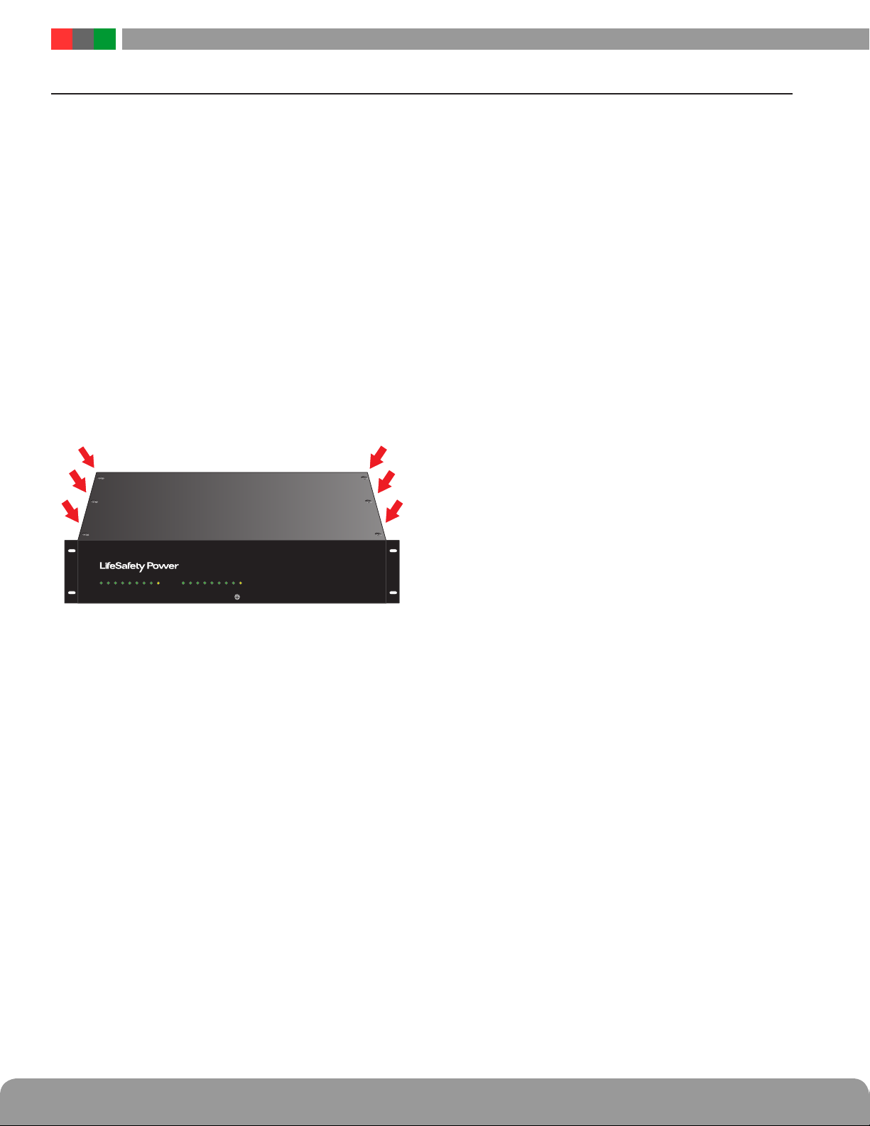
1.4 Making the Wiring Connections