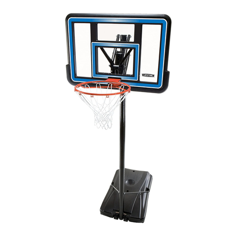
Lifetime 90160 User manual

1
Keep this Product ID Number and use when contacting Customer Service:
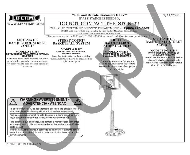
OWNER’S MANUAL
MODEL N° 90160
COPY

2
Save this owner’s manual for future reference and in the event that
the manufacturer has to be contacted.
**U.S. and Canada customers ONLY**
IF ASSISTANCE IS NEEDED,
DO NOT CONTACT THE STORE!
CALL OUR CUSTOMER SERVICE DEPARTMENT at
1 (800) 225-3865
HOURS: 7:00 a.m. to 5:00 p.m. Monday through Friday (Mountain Standard Time)
**Call or visit our Web site for Saturday hours**
Lifetime Products, Inc.
0/"OXs&REEPORT#ENTER"LDG$#LEARFIELD5TAH
**For customers outside the U.S. or Canada, please contact the store for assistance.**
REGISTER YOUR LIFETIME PRODUCT TODAY!
,)&%4)-%302/-)3%4/9/5
We invite you to read our privacy policy at www.lifetime.com
REGISTER today!
There are benefits to registering your Lifetime product. With our new online product registration form,
it’s fast and easy! Register with us at www.lifetime.com and enjoy these great benefits:
s2ECEIVEEXCLUSIVEMONEYSAVINGOFFERSFROM"UY,IFETIMECOMOURONLINESTOREASWELL
as NEW product notifications and special closeout promotions!
s)NTHEUNLIKELYEVENTOFAPRODUCTRECALLORSAFETYMODIlCATIONWEWILLNOTIFYYOU
s2EGISTERINGYOURPRODUCTGUARANTEESYOUWARRANTYSERVICE)FYOUDONOTREGISTERYOUR
PRODUCTYOURWARRANTYRIGHTSWILLNOTBEDIMINISHED"UTYOUWILLNEEDTOPROVIDEASALES
receipt to verify your product purchase date before warranty service will be provided.
Maintaining your privacy is our long-standing policy at Lifetime. And you can rest as-
sured that Lifetime will not sell or provide your personal data to other third parties, or
allow them to use your personal data for their own purposes.
INSTRUCTION #1076297 B 12/10/2010
COPY

3
Most injuries are caused by misuse and/or not following instructions. Use caution when using this product.
To ensure safety, do not attempt to assemble this product without reading and
FOLLOWINGALLINSTRUCTIONSCAREFULLY#HECKTHEENTIREBOXANDINSIDEALLPACKING
materials for parts and/or additional instruction material. "EFOREBEGINNINGASSEMBLY
identify and inventory all parts and hardware using the parts and hardware lists and
identifiers in this document. Proper and complete assembly, use and supervision
AREESSENTIALFORPROPERORIENTATIONANDTOREDUCETHERISKOFACCIDENTORINJURY!
HIGHPROBABILITYOFSERIOUSINJURYEXISTSIFTHISPRODUCTISNOTINSTALLEDMAINTAINED
and/or operated properly. Failure to comply with any of the warnings in this
INSTRUCTIONMANUALMAYRESULTINSERIOUSPERSONALINJURIESSUCHASCUTSBROKEN
BONESNERVEDAMAGEPARALYSISBRAININJURYORDEATH&AILURETOCOMPLYMAYALSO
result in property damage. Please heed all warnings and cautions.
&!),52%4/&/,,/74(%3%7!2.).'3-!92%35,4).3%2)/53).*529/202/0%249
DAMAGE AND WILL VOID WARRANTY.
s4HREECAPABLEADULTSARERECOMMENDEDFORTHISOPERATION
s)FUSINGALADDERDURINGASSEMBLYUSEEXTREMECAUTION
s"EFOREDIGGINGCONTACTUTILITYCOMPANYTOLOCATEUNDERGROUNDPOWERCABLESGAS
and water lines. Ensure that there are no overhead power lines within 20 ft. (7m)
radius of Pole location.
SAFETY INSTRUCTIONS
BEFORE BEGINNING ASSEMBLY
Keep the hardware bags and their contents separate. If any parts
are missing, call our Customer Service Department.
Identify and inventory all parts and hardware using the parts and
hardware lists and identifiers in this document.
4ESTlTALL"OLTSBYINSERTINGTHEMINTOTHEIRRESPECTIVEHOLES)F
NECESSARYCAREFULLYSCRAPEAWAYANYEXCESSPOWDERCOATING
buildup from inside the holes. Do not scrape away all of the
POWDERCOATING"AREMETALMAYRUST9OUMAYNEEDTOPOUND
SOME"OLTSINTOPLACEWITHAHAMMERORMALLET
TOOLS AND PARTS REQUIRED FOR THIS ASSEMBLY
*Two adults required to
complete assembly*
Only adults should set up the product. Do not allow children
in the setup area until assembly is complete.
Phillips Screwdriver
(1)
7/16” Wrench
(2)
Wood Block
(1) Included
(1)
Pliers
Rubber Mallet
(1)
1/2” Wrench
(2)
(7 80 lb bags)
9/16” Wrench
(2)
(1)
Electric Drill
v7RENCH
(2)
1/2” x 3’ Rebar
(1)
Shovel
Tape Measure
Cement Mix
(1)
(1)

5
This area is located at the top,
left-hand corner of the page
and indicates which tools
and hardware are needed to
complete the assembly steps
on a page.
Note:
!
Refer to the following areas throughout the instructions
to assist in the assembly process:
This area is usually located in the
bottom, left-hand corner of a step
and indicates that special attention
is needed to perform a particular
part of a step.
These areas are usually located in
the bottom, right-hand corner of a
step and indicate that damage to
the product or serious injury may
occur if the caution or warning is
not heeded. WARNING
ASSEMBLY GUIDES
TOOLS AND HARDWARE REQUIRED FOR THIS PAGE
CAUTION

6
PARTS LIST
ID Item Description Qty
!,( Top Pole 1
!,& Middle Pole 1
!,% "OTTOM0OLE 1
AJK 2IGHT"ACKBOARD"RACKET 1
AJJ ,EFT"ACKBOARD"RACKET 1
AJI "ACKBOARD 1
!,8 Rim 1
AKZ Net 1
!,$ Plastic Guard 1
!,, 0OLE"RACKET 1
AKC 3HORT%XTENSION!RM 2
!+" ,ONG%XTENSION!RM 2
AKQ Inner Channel 1
!," Outer Tube 1
AJS Channel Stop 1
AKI Handle 1
AMN Trigger 1
!*9 Spring 2
AMW 7OOD"LOCK 1
!,- Pole Cap 1
AJQ Center Frame Pad 1
!*8 Corner Frame Pad 2
AKP (EIGHT3TICKER 1
AMT 7ARNING3TICKER!PPLIEDTO-IDDLE0OLE 1
ID Item Description Qty
Pole Assembly Hardware (1068524)
ADS vXv3CREW 2
!": Xv3ELF$RILLING3CREW 2
AAF v7ASHER 2
!"" v#ENTERLOCK.UT 2
!"% vXv(EX"OLT 2
!"2 vXv3PACER 2
CIH $OMED#OUNTERSINK7ASHER 2
HARDWARE LIST

7
HARDWARE LIST
ID Item Description Qty
Backboard & Rim Assembly Hardware (1045426)
AAS vXv(EX"OLT 2
!"3 vXv'ALVANIZED3PACER 2
!!" v#ENTERLOCK.UT 2
AAJ v(EX4.UT 2
!"$ v7ASHER 2
!"& v2UBBER7ASHER 2
!"' vXv4AP"OLT 2
!"# vXv#ARRIAGE"OLT 2
AOU v5"OLT 1
!"+ v.YLOCK&LANGE.UT
AJW Compression Spring 2
AOW Spring Retainer Plate 1
AAV v*AM.UT 2
Backboard to Pole Assembly Hardware (1046466)
AAD vXv(EX"OLT 4
!", vXv"LACK3PACER 4
!!8 v#ENTERLOCK.UT 4
!". vXv3PACER 4
Handle Assembly Hardware (1046262)
APS ,OCK4AB 1
AEA 7ASHER 2
AAP Xv0HILLIPS3CREW 2
AQI Trigger Spring 1
!#9 vXv3CREW 2
AAC vXv(EX"OLT 1
AAN v#AP.UT 1
AAD vXv(EX"OLT 1
!!8 v#ENTERLOCK.UT 1
!"/ vXv0OLY3PACER 2
AAZ vXv(EX"OLT 1
!"" v#ENTERLOCK.UT 1
Frame Pad Assembly Hardware (HH00700)
ADP Xv3ELF$RILLING3CREW 10

8
Parts shown at 10% of Actual Size
ALHX
Top Pole
!,&X
Middle Pole
ALEX
"OTTOM0OLE
PARTS IDENTIFIER
!**X
,EFT"ACKBOARD"RACKET
!*+X
2IGHT"ACKBOARD"RACKET
43 ”
3/8
43 ”
3/8
AKCX
3HORT%XTENSION!RM
Warning Sticker
30 1/16”
AKBX
,ONG%XTENSION!RM
AKQX
Inner Channel
ALBX
Outer Tube
21 1/8”
43 ”
3/8
!*1X
Center Frame Pad
!*8X
Corner Frame Pad

9
AKZX
Net
!,8X
Rim
Parts shown at 5% of Actual Size
Parts shown at 10% of Actual Size
PARTS IDENTIFIER
!*)X
"ACKBOARD
Parts shown at 25% of Actual Size
!*3X
Channel Stop
ALLX
0OLE"RACKET
!*9X
Spring
ALMX
Pole Cap
AMNX
Trigger
AKIX
Handle
AKPX
(EIGHT3TICKER
ALDX
Plastic Guard
Part shown at 25% of
Actual Size

10
HARDWARE IDENTIFIER
POLE ASSEMBLY HARDWARE
Hardware shown at Actual Size
BACKBOARD TO RIM ASSEMBLY HARDWARE
Hardware shown at Actual Size
ADSX
vXv3CREW
ABZX
Xv3ELF$RILLING
Screw
ABBX
v#ENTERLOCK.UT
!!&X
v7ASHER
ABEX
vXv(EX"OLT
ABRX
vXv3PACER
AASX
vXv(EX"OLT
ABCX
vXv
#ARRIAGE"OLT
ABSX
vXv'ALVANIZED3PACER
ABGX
vXv4AP"OLT !!*X
v(EX4.UT ABDX
v7ASHER
AABX
v#ENTERLOCK.UT
!"&X
v2UBBER7ASHER
ABKX
v.YLOCK
Flange Nut
AAVX
v*AM.UT
CIHX
$OMED#OUNTERSINK
Washer

11
HARDWARE IDENTIFIER
BACKBOARD TO RIM ASSEMBLY HARDWARE (CONTINUED)
Hardware shown at 25% of Actual Size
!*7X
Compression Spring
AOUX
v5"OLT
AOWX
Spring Retainer Plate
AADX
vXv(EX"OLT
!!8X
1/2” Center
LOCK.UT
ABLX
vXv"LACK3PACER ABNX
vXv3PACER
BACKBOARD TO POLE ASSEMBLY HARDWARE
Hardware shown at Actual Size
7 1/8”
(Not actual length)
HANDLE ASSEMBLY HARDWARE
Hardware shown at Actual Size
APSX
,OCK4AB
ACYX
vXv3CREW
AACX
vXv(EX"OLT
7”
(Not actual length) ABOX
vXv0OLY3PACER
AAZX
vXv(EX"OLT

12
HARDWARE IDENTIFIER
AEAX
7ASHER
AAPX
Xv0HILLIPS
Screw
AQIX
Trigger Spring
AANX
v#AP.UT
!!8X
v#ENTERLOCK.UT
ABBX
v#ENTERLOCK.UT
AADX
vXv(EX"OLT
7 1/16”
(Not actual length)
HANDLE ASSEMBLY HARDWARE (CONTINUED)
Hardware shown at Actual Size
ADPX
Xv3ELF$RILLING3CREW
(Only eight of the 10 Screws will be used)
&2!-%0!$!33%-",9(!2$7!2%
Hardware shown at Actual Size

13
GROUND PREPARATION
HARDWARE REQUIRED
SEC
1
PARTS REQUIRED
TOOLS REQUIRED
Part shown at 10% of Actual Size
ALEX
"OTTOM0OLE
1/2” x 36” Rebar
Shovel
Tape Measure Cement Mix
XLB"AGS
Level
./(!2$7!2%2%15)2%$&/24()33%#4)/.

TOOLS AND HARDWARE REQUIRED FOR THIS PAGE
Dig a round hole 24” deep and 18” in diameter. If you live in an area
where frost heaves may pose a problem, consult your local building
inspector to determine the proper hole depth. The edge of the hole
should be flush with the edge of the playing surface.
SEC
1.1
Note: A Ground Sleeve is available as an alternative to cementing
the Pole into the ground. Please contact Customer Service or visit
Lifetime.com online for more information.
!
./(!2$7!2%2%15)2%$&/24()30!'%
-IXBAGSOFCONCRETE3AVEBAGOFCONCRETEMIXTOUSE
LATERINTHEASSEMBLY0OURTHEMIXEDCONCRETEINTOTHEHOLEUNTILITIS
filled to the level of the playing surface.
v
18”

15
TOOLS AND HARDWARE REQUIRED FOR THIS PAGE
ALE
v
-AKEAMARKINCHESFROMTHEDIMPLEDENDOFTHEBottom Pole
(ALE) (do not scratch the powder coating).
SEC
1.2
Slide the dimpled end of the Bottom Pole (ALE) into the cement up to
THEINCHMARK0OSITIONTHEPOLENEXTTOTHEPLAYINGSURFACE
SEC
1.3
./4//,3/2(!2$7!2%2%15)2%$&/24()30!'%

16
TOOLS AND HARDWARE REQUIRED FOR THIS PAGE
The slots in the Bottom Pole (ALE) must be parallel to the playing surface.
)FNECESSARYINSERTASTRAIGHTOBJECTARULERWIREETCTHROUGHTHE
SLOTSINTHE"OTTOM0OLE2OTATETHEPOLEUNTILTHESTRAIGHTOBJECTIS
parallel to the playing surface.
SEC
Note: Use a Level to make sure the Bottom Pole is standing vertical. Form
the cement into a downward slope away from the pole to allow water runoff.
Failure to do so may result in premature rusting of the Pole.
!
Playing Surface
./4//,3/2(!2$7!2%2%15)2%$&/24()30!'%

17
TOOLS AND HARDWARE REQUIRED FOR THIS PAGE
)NSERTTHEvXv2EBARNOTINCLUDEDINSIDETHEBottom Pole (ALE)
SOITISABOUTvFROMTHETOPOFTHEPOLE#HECKTHEPOLESEVERAL
TIMESWITHINTHElRSTHOURTOMAKESURETHATALLSIDESAREVERTICALAND
THATTHEINCHMARKREMAINSLEVELWITHTHESURFACE
SEC
1.5
Note: Allow 1-4 hours for the concrete to set before continuing.
!
1/2” x 36” Rebar
./(!2$7!2%2%15)2%$&/24()30!'%
Rebar

18
TOOLS AND HARDWARE REQUIRED FOR THIS PAGE
-IXTHEREMAININGBAGOFCONCRETE&ILLTHEBottom Pole (ALE) with
CONCRETEUNTILITJUSTBELOWTHESLOTSNEARTHETOPOFTHEPOLE$ONOT
OVERlLL4AMPTHECONCRETEDOWNINTHE"OTTOM0OLEWITHABROOM
HANDLETOREMOVEAIRPOCKETS#LEANALLCONCRETEOFFTHEOUTSIDEOF
the pole. Allow the concrete to set for at least 72 hours before installing the rest
of the system onto the Bottom Pole.
SEC
1.6
Cement Level
Inside Pole
Rebar
Note: STOP HERE! The concrete must cure for at least 72 hours (3 days) before
installing the rest of the system. In humid climates or wet weather, allow additional
time for the concrete to cure. Do not proceed until the curing process is complete.
!
./(!2$7!2%2%15)2%$&/24()30!'%

19
POLE ASSEMBLY
HARDWARE REQUIRED
PARTS REQUIRED
TOOLS REQUIRED
SEC
2
Parts shown at 10% of Actual Size
Phillips Screwdriver
Hardware shown at Actual Size
Wood Block
ADSX
vXv3CREW
ABZX
Xv3ELF$RILLING
Screw
ABBX
v#ENTERLOCK.UT
!!&X
v7ASHER
ABEX
vXv(EX"OLT
ABRX
vXv3PACER
ALHX
Top Pole
!,&X
Middle Pole
43 ”
3/8
43 ”
3/8
Warning Sticker
ALLX
0OLE"RACKET
Part shown at 25% of Actual Size
9/16” Wrench X Electric Drill
CIHX
$OMED#OUNTER
SINK7ASHER *Only one of the Domed Countersink Washers (CIH),
Xv3ELF4APPING3CREWS!":ANDvXv
Screws (ADS) will be used in this section. The remaining
hardware will be used later in the assembly.

20
TOOLS AND HARDWARE REQUIRED FOR THIS PAGE
Insert the vXv(EX"OLTS!"% with the v7ASHERS!!& into the
-IDDLE0OLE!,& as shown. Then slide the vXv3PACERS!"2 onto
THE(EX"OLTS
SEC
2.1
!,&
ABE
ABR
Warning
Sticker
!!&
Large Holes
Small Holes
!!&X
ABEX
ABRX
./4//,32%15)2%$&/24()30!'%
Table of contents
Other Lifetime Accessories manuals

Lifetime
Lifetime 90180 User manual

Lifetime
Lifetime 51544 User manual

Lifetime
Lifetime 71559 User manual

Lifetime
Lifetime 1533 User manual

Lifetime
Lifetime 71523 User manual

Lifetime
Lifetime 1529 User manual

Lifetime
Lifetime QUICK ADJUST 90023 User manual

Lifetime
Lifetime 90165 User manual

Lifetime
Lifetime 90179 User manual

Lifetime
Lifetime FreeStyle User manual
Popular Accessories manuals by other brands

celesco
celesco MTA-3 installation guide

Tobii Dynavox
Tobii Dynavox PCEye 5 Getting started guide

PCB Piezotronics
PCB Piezotronics PCB-(M)320C18 Installation and operating manual

Daewoo
Daewoo SDA1806 quick start guide

Meade
Meade Ultrawedge operating instructions

IME
IME enginko EGK-LW20W00 operating manual