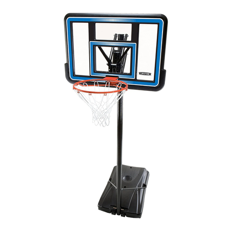
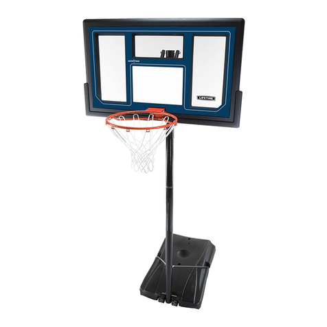
Lifetime 90191 User manual

1
Keep this Product ID Number and use when contacting Customer Service:
OWNER’S MANUAL
MODEL N° 90191
COPY

2
Save this owner’s manual for future reference and in the event that
the manufacturer has to be contacted.
**U.S. and Canada customers ONLY**
IF ASSISTANCE IS NEEDED,
DO NOT CONTACT THE STORE!
CALL OUR CUSTOMER SERVICE DEPARTMENT at
1 (800) 225-3865
HOURS: 7:00 a.m. to 5:00 p.m. Monday through Friday (Mountain Standard Time)
**Call us or visit our Web site for Saturday hours**
Lifetime Products, Inc.
0/"OXs&REEPORT#ENTER"LDG$#LEARFIELD5TAH
**For customers outside the U.S. or Canada, please contact the store for assistance.**
REGISTER YOUR LIFETIME PRODUCT TODAY!
,)&%4)-%302/-)3%4/9/5
We invite you to read our privacy policy at www.lifetime.com
2%')34%2TODAY
4HEREAREBENElTSTOREGISTERINGYOUR,IFETIMEPRODUCT7ITHOURNEWONLINEPRODUCTREGISTRATIONFORM
ITSFASTANDEASY2EGISTERWITHUSATWWWLIFETIMECOMANDENJOYTHESEGREATBENElTS
s2ECEIVEEXCLUSIVEMONEYSAVINGOFFERSFROM"UY,IFETIMECOMOURONLINESTOREASWELL
as NEW product notifications and special closeout promotions!
s)NTHEUNLIKELYEVENTOFAPRODUCTRECALLORSAFETYMODIlCATIONWEWILLNOTIFYYOU
s2EGISTERINGYOURPRODUCTGUARANTEESYOUWARRANTYSERVICE)FYOUDONOTREGISTERYOUR
product, your warranty rights will not be diminished. But you will need to provide a sales
receipt to verify your product purchase date before warranty service will be provided.
Maintaining your privacy is our long-standing policy at Lifetime. And you can rest as-
sured that Lifetime will not sell or provide your personal data to other third parties, or
allow them to use your personal data for their own purposes.
).3425#4)/. 2/15/2011
COPY

3
Most injuries are caused by misuse and/or not following instructions. Use caution when using this product.
To ensure safety, do not attempt to assemble this product without reading and
following all instructions carefully. Check the entire box and inside all packing
materials for parts and/or additional instruction material. Before beginning assembly,
identify and inventory all parts and hardware using the parts and hardware lists and
identifiers in this document. Proper and complete assembly, use and supervision
are essential for proper orientation and to reduce the risk of accident or injury. A
high probability of serious injury exists if this product is not installed, maintained,
and/or operated properly. Failure to comply with any of the warnings in this
instruction manual may result in serious personal injuries such as cuts, broken
bones, nerve damage, paralysis, brain injury, or death. Failure to comply may also
result in property damage. Please heed all warnings and cautions.
&!),52%4/&/,,/74(%3%7!2.).'3-!92%35,4).3%2)/53).*529/202/0%249
$!-!'%!.$7),,6/)$7!22!.49
s4HREECAPABLEADULTSARERECOMMENDEDFORTHISOPERATION
s)FUSINGALADDERDURINGASSEMBLYUSEEXTREMECAUTION
s"EFOREDIGGINGCONTACTUTILITYCOMPANYTOLOCATEUNDERGROUNDPOWERCABLESGAS
and water lines. Ensure that there are no overhead power lines within 20 ft. (7m)
radius of Pole location.
SAFETY INSTRUCTIONS
BEFORE BEGINNING ASSEMBLY
Keep the hardware bags and their contents separate. If any parts
are missing, call our Customer Service Department.
Identify and inventory all parts and hardware using the parts and
hardware lists and identifiers in this document.
Test fit all Bolts by inserting them into their respective holes. If
necessary, carefully scrape away any excess powder coating
buildup from inside the holes. Do not scrape away all of the
powder coating. Bare metal may rust. You may need to pound
some Bolts into place with a hammer or mallet.
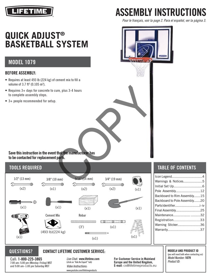

TOOLS AND PARTS REQUIRED FOR THIS ASSEMBLY
*Two adults required to
complete assembly*
/NLYADULTSSHOULDSETUPTHEPRODUCT$ONOTALLOWCHILDREN
INTHESETUPAREAUNTILASSEMBLYISCOMPLETE
Phillips Screwdriver
(1)
v7RENCH
(2)
!-77OOD"LOCK
(1, included)
(1)
Pliers
Rubber Mallet
(1)
v7RENCH
(2)
v7RENCH
(2)
(1)
Electric Drill
v7RENCH
(2)
30” Rebar Shovel
Tape Measure
Cement Mix
Level
(1)
(1)
(1)
(1)
(x7 80 lb. bags)
Hammer
(1)

5
This area is located at the top,
left-hand corner of the page
and indicates which tools
and hardware are needed to
COMPLETETHEASSEMBLYSTEPS
on a page.
Note:
!
Refer to the following areas throughout the instructions
to assist in the assembly process:
4HISAREAISUSUALLYLOCATEDINTHE
bottom, left-hand corner of a step
and indicates that special attention
is needed to perform a particular
part of a step.
4HESEAREASAREUSUALLYLOCATEDIN
the bottom, right-hand corner of a
step and indicate that damage to
THEPRODUCTORSERIOUSINJURYMAY
occur if the caution or warning is
not heeded. 7!2.).'
ASSEMBLY GUIDES
TOOLS AND HARDWARE REQUIRED FOR THIS PAGE
CAUTION

6
PARTS LIST
ID Item Description Qty
!,( Top Pole 1
!,& Middle Pole 1
!,% Bottom Pole 1
AJK Right Backboard Bracket 1
AJJ ,EFT"ACKBOARD"RACKET 1
AJI Backboard 1
AJX Corner Frame Guard 2
AJQ Center Frame Guard 1
!,8 Rim 1
AKZ Net 1
!,$ Plastic Guard 1
!,, Pole Bracket 1
AKC Short Extension Arm 2
AKB ,ONG%XTENSION!RM 2
AKQ Inner Channel 1
!," Outer Tube 1
AJS Channel Stop 1
AKI Handle Grip 2
AMN Trigger 2
CNF ,OCK4AB 1
CNG Handle Brace 1
CNJ Outer Tube Bushing 1
AJY Counterbalance Spring 2
AMW Wood Block 1
!,- Pole Cap 1
AKP Height Sticker 1
AMT Warning Sticker (Applied to Middle Pole) 1
ID Item Description Qty
Pole Assembly Hardware (1068524)
ADS 1/4” x 3/4” Screw 2
ABZ Xv3ELF4APPING3CREW 2
AAF 3/8” Washer 2
ABB 3/8” Centerlock Nut 2
ABE 3/8” x 4” Hex Bolt 2
ABR 1/2” x 3.41” Spacer 2
CIH Domed Countersink Washer 2
HARDWARE LIST

7
HARDWARE LIST
ID Item Description Qty
Backboard to Rim Assembly Hardware (1045426)
AAS 1/4” x 2 3/4” Hex Bolt 2
ABS 1/2” x 2 5/16” Galvanized Spacer 2
ABC 5/16” x 1 1/4” Carriage Bolt 2
ACS .38” x 1” Steel Spacer 2
AAB 1/4” Centerlock Nut 2
AAJ v(EX4.UT 2
ABD 5/16” Washer 2
ABF 7/16” Rubber Washer 2
ABG 5/16” x 2 1/2” Tap Bolt 2
AOU v5"OLT 1
ABK 5/16” Nylock Flange Nut 6
AJW Compression Spring 2
AOW Spring Retainer Plate 1
AAV 5/16” Jam Nut 2
Backboard to Pole Assembly Hardware (1046466)
AAD 1/2” x 7 1/8” Hex Bolt 4
!", .69” x .59” Black Spacer 4
AAX 1/2” Centerlock Nut 4
ABN 1/2” x 1/8” Spacer 4
Handle Assembly Hardware (1069824)
AAJ v(EX4.UT 4
CNI 5/16” x1 Pan Head Screw 4
AQH Trigger Spring 2
AAN 5/16” Cap Nut 1
AAX 1/2” Centerlock Nut 1
AZP 1/4” Nylock Nut 2
ABB 3/8” Centerlock Nut 1
ADR #7 x 3/8” Phillips Screw 4
AAC 5/16” x 1 3/4” Hex Bolt 1
CNH vXv5.#!3CREW 2
ABO 1/2” x 1” Poly Spacer 2
AAD 1/2” x 7 1/8” Hex Bolt 1
AAZ 3/8” x 7” Hex Bolt 1
CNE 4WO(EAD3NAP"UTTON 1
Frame Guard Assembly Hardware (HH00700)
ADP Xv3ELF$RILLING3CREW 10

8
Parts shown at 10% of Actual Size
ALH (x1)
Top Pole
!,& (x1)
Middle Pole
ALE (x1)
Bottom Pole
PARTS IDENTIFIER
!** (x1)
,EFT"ACKBOARD"RACKET
!*+ (x1)
Right Backboard Bracket
43 ”
3/8
43 ”
3/8
AKC (x2)
Short Extension Arm
7ARNING3TICKER
30 1/16”
AKB (x2)
,ONG%XTENSION!RM
AKQ (x1)
Inner Channel
ALB (x1)
Outer Tube
!*8 (x2)
Corner Frame Guard
!*1 (x1)
Center Frame Guard
21 1/8”
43 3/8”

9
Parts shown at 25% of Actual Size
PARTS IDENTIFIER
ALD (x1)
Plastic Guard
!*3 (x1)
Channel Stop
!*9 (x2)
Counterbalance Spring ALM (x1)
Pole Cap
ALL (x1)
Pole Bracket
AKP (x1)
Height Sticker
AKI (x2)
Handle Grip
AMN (x2)
Trigger
#.' (x1)
Handle Brace
#.& (x1)
,OCK4AB
#.* (x1)
Outer Tube
Bushing

10
AKZ (x1)
Net
!,8 (x1)
Rim
!*) (x1)
Backboard
Parts shown at 5% of Actual Size
Parts shown at 10% of Actual Size
PARTS IDENTIFIER

11
HARDWARE IDENTIFIER
0/,%!33%-",9(!2$7!2%
Hardware shown at Actual Size
"!#+"/!2$4/2)-!33%-",9(!2$7!2%
Hardware shown at Actual Size
ADS (x2)
1/4” x 3/4” Screw
ABZ (x2)
Xv3ELF4APPING3CREW
ABB (x2)
3/8” Centerlock Nut
!!& (x2)
3/8” Washer
ABE (x2)
3/8” x 4” Hex Bolt
ABR (x2)
1/2” x 3.41” Spacer
AAS (x2)
1/4” x 2 3/4” Hex Bolt
ABC (x2)
5/16” x 1 1/4” Carriage Bolt
CIH (x2)
Domed Counter
sink Washer
AAB (x2)
1/4” Centerlock Nut
!"' (x2)
5/16” x 2 1/2” Tap Bolt
AAV (x2)
5/16”Jam Nut
ABS (x2)
1/2” x 2 5/16” Galvanized Spacer
ACS (x2)
.38” x 1” Steel Spacer

12
HARDWARE IDENTIFIER
"!#+"/!2$4/2)-!33%-",9(!2$7!2%#/.4).5%$
Hardware shown at Actual Size
Hardware shown at 25% of Actual Size
!*7 (x2)
Compression Spring
AOU (x1)
v5"OLT
!/7 (x1)
Spring Retainer Plate
AAD (x4)
1/2” x 7 1/8” Hex Bolt
!!* (x2)
v(EX4.UT
ABD (x2)
5/16” Washer
!"& (x2)
7/16” Rubber Washer
ABK (x6)
5/16” Nylock Flange Nut
!!8 (x4)
1/2” Centerlock Nut
ABL (x4)
.69” x .59” Black Spacer
ABN (x4)
1/2” x 1/8” Spacer
"!#+"/!2$4/0/,%!33%-",9(!2$7!2%
Hardware shown at Actual Size
7 1/8”
(Not actual length)
(!.$,%!33%-",9(!2$7!2%
Hardware shown at Actual Size
7”
(Not actual length) ABO (x2)
1/2” x 1” Poly Spacer
AAZ (x1)
3/8” x 7” Hex Bolt

13
HARDWARE IDENTIFIER
(!.$,%!33%-",9(!2$7!2%#/.4).5%$
Hardware shown at Actual Size
&2!-%'5!2$!33%-",9(!2$7!2%
Hardware shown at Actual Size
ADP (x10)
Xv3ELF$RILLING3CREW
/NLYEIGHTOFTHE3CREWSWILLBEUSED
ADR (x4)
#7 x 3/8”
Phillips Screw
AQH (x2)
Trigger Spring
CNI (x4)
5/16” x 1” Pan Head Screw
AAC (x1)
5/16” x 1 3/4” Hex Bolt
AAN (x1)
5/16” Cap Nut
!!8 (x1)
1/2” Centerlock Nut
ABB (x1)
3/8” Centerlock
Nut
AAD (x1)
1/2” x 7 1/8” Hex Bolt
7 1/8”
(Not actual length)
AZP (x2)
1/4” Nylock Nut
CNE (x1)
4WO(EAD3NAP"UTTON
CNH (x2)
vXv
5.#!3CREW
!!* (x4)
v(EX4.UT

'2/5.$02%0!2!4)/.
HARDWARE REQUIRED
SEC
1
PARTS REQUIRED
TOOLS REQUIRED
Part shown at 10% of Actual Size
ALE (x1)
Bottom Pole
1/2” x 36” Rebar
Shovel
Tape Measure Cement Mix
(x7 80 lb. Bags)
Level
./(!2$7!2%2%15)2%$&/24()33%#4)/.

15
TOOLS AND HARDWARE REQUIRED FOR THIS PAGE
Dig a round hole 24” deep and 18” in diameter. If you live in an area
where frost heaves may pose a problem, consult your local building
inspector to determine the proper hole depth. The edge of the hole
should be flush with the edge of the playing surface.
SEC
1.1
Note: A Ground Sleeve is available as an alternative to cementing
the Pole into the ground. Please contact Customer Service or visit
Lifetime.com online for more information.
!
./(!2$7!2%2%15)2%$&/24()30!'%
Mix 6 1/2 bags of concrete. Save 1/2 bag of concrete mix to use
later in the assembly. Pour the mixed concrete into the hole until it is
filled to the level of the playing surface.
v
18”

16
TOOLS AND HARDWARE REQUIRED FOR THIS PAGE
ALE
v
Make a mark 14.5 inches from the dimpled end of the Bottom Pole
(ALE) (do not scratch the powder coating).
SEC
1.2
Slide the dimpled end of the Bottom Pole (ALE) into the cement up to
THEINCHMARK0OSITIONTHEPOLENEXTTOTHEPLAYINGSURFACE
SEC
1.3
./4//,3/2(!2$7!2%2%15)2%$&/24()30!'%

17
TOOLS AND HARDWARE REQUIRED FOR THIS PAGE
The slots in the Bottom Pole (ALE) must be parallel to the playing surface.
If necessary, insert a straight object (a ruler, wire, etc.) through the
slots in the Bottom Pole. Rotate the pole until the straight object is
parallel to the playing surface.
SEC
Note: Use a Level to make sure the Bottom Pole is standing vertical. Form
the cement into a downward slope away from the pole to allow water runoff.
Failure to do so may result in premature rusting of the Pole.
!
0LAYING3URFACE
./4//,3/2(!2$7!2%2%15)2%$&/24()30!'%

18
TOOLS AND HARDWARE REQUIRED FOR THIS PAGE
Insert the 1/2” x 36” Rebar (not included) inside the Bottom Pole (ALE)
so it is about 15” from the top of the pole. Check the pole several
times within the first hour to make sure that all sides are vertical and
THATTHEINCHMARKREMAINSLEVELWITHTHESURFACE
SEC
1.5
Note: Allow 1-4 hours for the concrete to set before continuing.
!
1/2” x 36” Rebar
./(!2$7!2%2%15)2%$&/24()30!'%
Rebar

19
TOOLS AND HARDWARE REQUIRED FOR THIS PAGE
Mix the remaining 1/2 bag of concrete. Fill the Bottom Pole (ALE) with
concrete until it just below the slots near the top of the pole. Do not
overfill. Tamp the concrete down in the Bottom Pole with a broom
handle to remove air pockets. Clean all concrete off the outside of
the pole. Allow the concrete to set for at least 72 hours before installing the rest
OFTHESYSTEMONTOTHE"OTTOM0OLE
SEC
1.6
Cement Level
Inside Pole
Rebar
Note: STOP HERE! The concrete must cure for at least 72 hours (3 days) before
installing the rest of the system. In humid climates or wet weather, allow additional
time for the concrete to cure. Do not proceed until the curing process is complete.
!
./(!2$7!2%2%15)2%$&/24()30!'%

20
POLE ASSEMBLY
HARDWARE REQUIRED
SEC
2
Hardware shown at Actual Size
ADS (x2)*
1/4” x 3/4” Screw
ABZ (x2)*
Xv3ELF4APPING3CREW ABB (x2)
3/8” Centerlock Nut
!!& (x2)
3/8” Washer
ABE (x2)
3/8” x 4” Hex Bolt
ABR (x2)
1/2” x 3.41” Spacer
CIH (x2)*
Domed Countersink Washer
.OTE/NLYONEXv3ELF4APPING3CREW!":ONE$OMED#OUNTER
SINK7ASHER#)(ANDONEvXv0AN(EAD3CREW!$3WILLBEUSED
FORTHISSECTION3AVETHEREMAININGHARDWAREFORLATERINTHEASSEMBLY
Table of contents
Other Lifetime Accessories manuals

Lifetime
Lifetime QUICK ADJUST 90023 User manual

Lifetime
Lifetime 71559 User manual

Lifetime
Lifetime 51587 Quick start guide

Lifetime
Lifetime FreeStyle User manual

Lifetime
Lifetime 90179 User manual

Lifetime
Lifetime 90180 User manual

Lifetime
Lifetime 51544 User manual

Lifetime
Lifetime FREESTANDINGPOWER LIFT 71730 Datasheet

Lifetime
Lifetime Elite 51546 Datasheet

Lifetime
Lifetime 1529 User manual
Popular Accessories manuals by other brands

celesco
celesco MTA-3 installation guide

Tobii Dynavox
Tobii Dynavox PCEye 5 Getting started guide

PCB Piezotronics
PCB Piezotronics PCB-(M)320C18 Installation and operating manual

Daewoo
Daewoo SDA1806 quick start guide

Meade
Meade Ultrawedge operating instructions

IME
IME enginko EGK-LW20W00 operating manual