LIMIT Limit 21 User manual

21

Red Black
fig.1 DC/AC Voltage Measurement
Red Black
fig.2 Testing for Continuity
40A
400A
fig.3 DC/AC Current Measurement
Screw
fig.4 Replacing the Battery
Illustrations
1
2
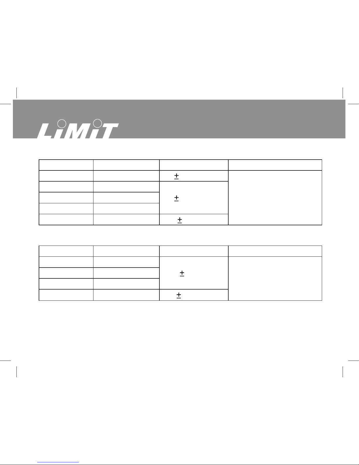
A. DC Voltage
Range Resolution Accuracy Overload protection
400.0mV
4.000V
40.00V
400.0V
600V
0.1mV
1mV
10mV
100mV
1V
(0.8%+3)
(0.8%+1)
(1%+3)
600V DC/AC
B. AC Voltage
Range Resolution Accuracy Overload protection
4.000V
40.00V
400.0V
600V
1mV
10mV
100mV
1V
(1%+5)
(1.2%+5)
600V DC/AC
21

3
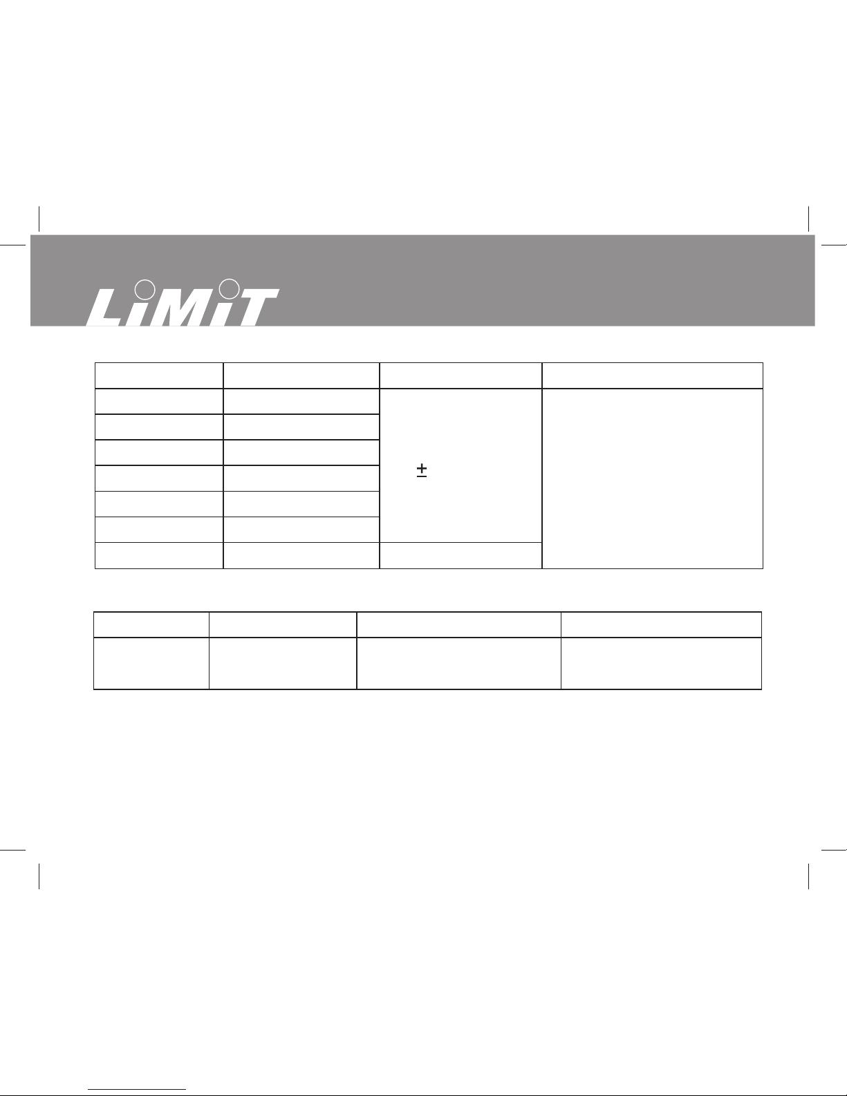
C. Resistance
Range Resolution Accuracy Overload protection
400.0
4.000k
40.00k
400.0k
4.000M
40.00M
100m
1
10
100
1k
10k
(1.2%+2)
(1%+2)
(1.2%+2)
(1.5%+2)
600Vp
D. Diode Test
Range Resolution Accuracy Overload protection
1mV Display forward voltage
drop nearest value 600Vp
E. Continuity Test
Range Resolution Accuracy Overload protection
100m Around 50 ,
the buzzer beeps 600Vp
Tables
F. Frequency
Range Resolution Accuracy Overload protection
10Hz
100Hz
1kHz
10kHz
100kHz
1MHz
10MHz
0.001Hz
0.01Hz
0.1Hz
1Hz
10Hz
100Hz
1kHz
(0.1%+3) 600Vp
For reference only
G. Duty Cycle
Range Resolution Accuracy Overload protection
0.1% For reference only 600Vp0.1%~99.9%
4
21
5
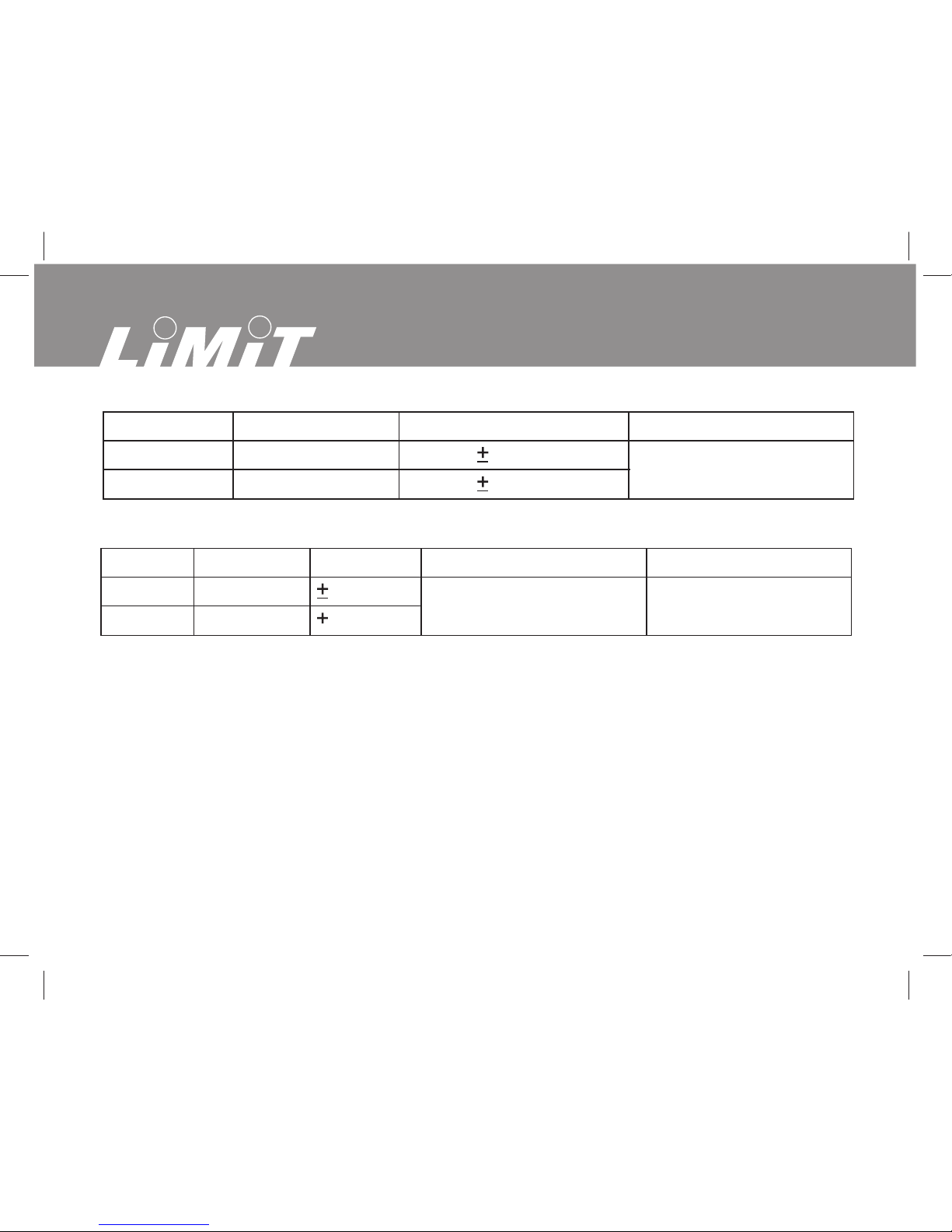
H. DC Current
Range Resolution Accuracy Overload protection
0.01A
0.1A 400A DC/AC
40.00A
400.0A (2%+5)
(2%+3)
I. AC Current
Range Resolution Accuracy Overload protection
0.01A
0.1A 400A DC/AC
40.00A
400.0A (2.5%+8)
(2.5%+5) 50Hz ~ 60Hz
Frequency Response
Tables

21
6
Language Contents
Language page
English ································································································7-14
Svenska ····························································································15-21
Norsk·································································································22-28
Dansk································································································29-35
Suomi································································································36-42
Deutsch·····························································································43-51
Nederlands························································································52-60
Français ····························································································61-69
Italiano·······························································································70-78
Español ·····························································································79-87
Português··························································································88-96
Ελληvikά··························································································97-105
Polski·····························································································106-115
Eesti ······························································································116-123
LietuviŠkai·····················································································124-131
Latviski ··························································································132-139
Pycckий ························································································140-148

7
Contents
Overview
General specification
Safety information
Voltage DC and AC
Current DC and AC
Resistance
Frequence and Duty cycle
Diodes test
Continuity test
Battery
English

8
Overview
This Operating Manual covers information on safety and cautions. Please read the
relevant information carefully and observe all the Warnings and Notes strictly.
Limit 21 is a clampmeter/multimeter for professional use. The instrument have
autorange and the display have large digits, shows rotary switch position witch
makes this instrument easy to handle for the user. For indoor use.
General Specifications
Measuring range and accuracy see page 2.
• Auto range.
• Display shows selected function.
• Maximum Display: 3999 or 3 ¾ digits.
• Displays OL when the instrument is overloaded.
• Max conductor diameter for clamp 26 mm.
• Sleep mode. Instrument turn off automatic if not active for 15 minutes.
• Measurement Speed: Updates 3 times /second.
• Temperature: Operating: 0°C~30°C
Storage: -20°C~60°C
• Battery 1 pcs 9 V Type 6F22.
English

9
• Safety/Compliances: IEC61010 CAT II 600V CAT III 300 V over voltage and
double insulation standard.
• Certification: CE
Safety Information
This Meter complies with the standards IEC61010: in pollution degree 2, category
CAT II 600V, CAT III 300V over voltage and double insulation.
Warning
To avoid possible electric shock or personal injury, and to avoid possible damage
to the Meter or to the equipment under test, adhere to the following rules:.
• Before using the Meter inspect the case. Do not use the Meter if it is damaged or
the case (or part of the case) is removed. Look for cracks or missing plastics. Pay
attention to the insulation around the connectors.
• Inspect the test leads for damages insulation or exposed metal. Check the test
leads for continuity.
• Do not apply more than the rated voltage, as marked on the Meter, between the
terminals or between any terminal and the grounding.
English

10
• The rotary switch should be placed in the right position and no any changeover of
range shall be made during measurement is conducted to prevent damage of the
Meter.
• Never attempt an in-circuit current measurement where the voltage between
terminals and ground is greater than 600 V.
• When the Meter working at an effective voltage over 60V in DC or 42V rms in AC,
special care should be taken for there is danger of electric shock.
• Do not use or store the Meter in an environment of high temperature; humidity,
explosive, inflammable and strong magnetic fields. The performance of the Meter
may deteriorate after dampened.
• When using the test leads, keep your fingers behind the finger guards.
• Disconnect circuit power and discharge all high-voltage capacitors before testing
resistance, continuity, diodes and current.
• Replace the battery as soon as the battery indicator appears. Whit to low battery,
the Meter might produce false readings that can lead to electric shock and personal
injury.
Functional buttons
Select • Change between DC and AC for voltage and current measurement.
• Change between continuity and diod test.
English

11
RELΔ• Relative mode for Current measurement.
• Select manual range for Voltage and Resistance measurement.
• Change between Hz and duty cycle %.
Hold • ON/OFF for hold function. H shows on display when value is
frozen.
Voltage measurement DC and AC (See fig 1)
1. Insert red test lead into the HzDuty%Vterminal and black test lead into the
COM terminal.
2. Set the rotary switch to V position.
3. Select DC or AC with select button. Display shows DC or AC.
4. Push RELbutton for manual ranging. AUTO disappere from the display. When
the value is
unknown always start from highest range.
5. Connect the test leads across with the object being measured. The measured
value shows on the display.
Current measurement DC and AC (See fig 3).
1. Set the rotary switch to 40 A or 400 A position. Start with 400 A when the value
is unknown.
2. Select DC or AC with select button. Display shows DC or AC.
English

12
3. Open the jaws and center one of the conductor. Make sure the conductor is
placed at center of the jaw. Only one conductor at each time can be measured.
The measured value shows on the display.
4. Push RELbutton for relative mode. It subtracts a stored value from the present
value. Displays shows .
Resistance measurement (See fig 1)
1. Insert red test lead into the HzDuty%Vterminal and black test lead into the
COM terminal.
2. Set the rotary switch to position. Displays shows .
3. Push RELbutton for manual ranging. AUTO disappere from the display. When
the value is
unknown always start from highest range.
4. Connect the test leads across with the object being measured. The measured
value shows on the display.
Note
• The test leads can add 0.1to 0.3of error to resistance measurement. To
obtain precision readings in low-resistance measurement, that is the range of 200,
short-circuit the input terminals beforehand and record the reading obtained. This is
the additional resistance from the test lead.
• OL displays when the circuit is open or the resistor value is higher than max
range.
English

13
Frequency and Duty Cycle measurement (See fig 2)
1. Insert red test lead into the HzDuty%Vterminal and black test lead into the
COM terminal.
2. Set the rotary switch to HzDuty% position.
3. Push RELbutton to select Hz or Duty Cycle. Displays shows Hz or %.
4. Connect the test leads across with the object being measured. The measured
value shows on the display.
Diode test (See fig 2)
Use the diode test to check diodes, transistors, and other semiconductor devices.
The diode test sends a current through the semiconductor junction, and then
measures the voltage drop across the junction. A good silicon junction drops
between 0.5V and 0.8V.
To test a diode out of a circuit, connect as follows:
1. Insert red test lead into the HzDuty%Vterminal and black test lead into the
COM terminal.
2. Set the rotary switch to diode position.
3. Push select button to select diode function. Displays shows diode symbol.
4. For forward voltage drop readings on any semiconductor component, place the
red test lead on the component’s anode and
place the black test lead
on the component’s cathode.
The measured value shows on the display.
English

14
Continuity test (See fig 2)
To test for continuity, connect as follows:
1. Insert red test lead into the HzDuty%Vterminal and black test lead into the
COM terminal.
2. Set the rotary switch to continuity position.
3. Push select button to select continuity function. Displays shows continuity
symbol.
4. Connect the test leads across with the object being measured. The buzzer
sounds if the resistance of a circuit under test is less than 50.
Replacing the Battery (See figure 4)
Replace battery as soon battery symbol is shown on display.
1. Disconnect the connection between the testing leads and the circuit under test
when battery indicator appears on the display.
2. Turn the Meter to OFF position.
3. Remove the screw, and separate the battery lid.
4. Replace the battery with 1 pcs 9 V Type 6F22.
5. Rejoin the battery lid and the screw.
English

15
Innehåll
Allmänt
Specifikationer
Säkerhetsföreskrifter
Spänningsmätning DC och AC
Strömstyrka DC och AC
Resistansmätning
Frekvensmätning och Pulskvot (duty cycle)
Diodtest
Kontinuitetstest
Batteri
Svenska

16
Allmänt
Denna bruksanvisning innehåller information om säkerhet och handhavande.
Läs noggrant igenom och observera alla varningar och säkerhetsföreskrifter.
Limit 21 är en tångampermeter/multimeter för framförallt yrkesmässig användning
vid mätning, kontroll och felsökning. Avsedd för inomhusanvändning.
Instrumentet har automatiskt områdesval. Displayen har stora siffror, visar också
valt mätområde, vilket gör instrumentet enkelt och tillförlitligt för användaren.
Specifikationer
Mätområden och noggrannhet se sid 2.
- Automatiskt områdesval.
- Displayen visar valt mätområde.
- Display 3¾ siffra eller 3999.
- Vid överbelastning visar displayen OL.
- Max kabeldiameter för tång 26 mm.
- Automatisk avstängning efter 15 minuter oaktivt.
- Mäthastighet 3 gånger per sekund.
- Temperatur. Arbetstemperatur 0 – 30ºC. Förvaringstemperatur – 20 - 60ºC.
- Batteri. 1 st 9 V standardbatteri typ 6F22.
- Säkerhet enligt IEC61010 CAT II 600V/ CAT III 300 V.
- Certifikat CE.
Svenska

17
Säkerhetsföreskrifter
Detta instrument uppfyller standard enligt IEC61010, Isolation CAT II 600 V, CAT
III 300 V.
Varning
Att undvika elektriska chocker eller personliga skador läs säkerhetsföreskrifterna
och ta del av nedanstående anvisningar innan ni tar instrumentet i bruk.
- Kontrollera att instrumentet är oskadat och inga sprickor finns i höljet. Kontrollera
speciellt isolationen kring testkabelanslutningarna.
- Kontrollera att testkablarna är oskadade.
- Anslut inte till högre spänning än instrumentet är märkt för mellan
kopplingsanslutningarna eller mellan fas och jord.
- Vridomkopplaren skall vara i inställd på korrekt position och skall inte ändras
under pågående mätning.
- Anslut aldrig testkablarna till en strömkrets där spänning till jord är större än 600
V.
- När instrumentet mäter en effektiv spänning över 60 V DC eller 42 V AC skall
extra försiktighet iakttas.
- Förvara inte instrumentet där det kan utsättas för höga temperatur, hög
luftfuktighet, explosionsrisk eller kraftiga magnetiska fält.
- Håll fingrar bakom skyddet på testkablarna.
Svenska

18
- Bryt strömmen före mätning av motstånd, kontinuitet, dioder eller strömstyrka.
- Byt batteri så fort batteriindikatorn på displayen visas.
Funktionsknappar
Select Växlar mellan V-- likström DC eller V~ växelström AC.
Växlar mellan Kontinuitet och Diod test när vridkopplaren är
inställd för någotdera.
RELΔRelativt mätvärde vid mätning av ampere.
För manuellt områdesval vid V och Ω.
Växla mellan Hz och Pulskvot (duty cycle) %.
Hold - På/av knapp för holdfunktionen. H visas på displayen när
mätvärdet är låst.
Spänningsmätning DC och AC (Se fig 1)
1. Sätt den röda testkabeln i HzDuty%VΩ-anslutningen och den svarta testkabeln i
COM-anslutningen.
2. Sätt vridkopplaren på V-läge.
3. Välj mellan V-- likström DC eller V~ växelström AC med SELECT knappen. DC
eller AC visas på displayen.
4. För manuellt områdesval tryck RELΔ. AUTO försvinner från displayen. Börja på
högsta läget om värdet är okänt.
5. Anslut testkablarna till mätobjektet. Mätvärdet visas på displayen.
Svenska

19
Strömstyrka DC och AC (Se fig 3)
1. Sätt vridkopplaren på 40 A eller 400 A läget. Börja på högsta läget om värdet är
okänt.
2. Välj mellan A-- likström DC eller A~ växelström AC med SELECT knappen. DC
eller AC visas på displayen.
3. Öppna tången och slut tången om en ledare. Endast en ledare i sänder skall
placeras i tången och sträva att placera ledaren så centralt som möjligt i tången.
4. Tryck RELΔknappen för att nollställa ett utgångsmätvärde och endast visa
skillnaden mellan utgångsvärdet och kommande mätvärden. Δvisas på displayen.
OL visas på displayen om mätområdet är för lågt.
Resistansmätning (Se fig 1)
1. Sätt den röda testkabeln i HzDuty%VΩanslutningen och den svarta testkabeln i
COM-anslutningen.
2. Sätt vridkopplaren till Ωläget.
3. För manuellt områdesval tryck RELΔ. AUTO försvinner från displayen. Börja på
högsta läget om värdet är okänt.
4. Anslut testkablarna till mätobjektet. Mätvärdet visas på displayen.
Testkablarnas resistans är 0,1 - 0,2 Ω. Detta kan medföra mätfel vid låga
resistanssvärden. OL visas på displayen när kretsen är bruten eller motståndet är
större än instrumentets max värde.
Svenska
Table of contents
Languages:
Other LIMIT Multimeter manuals


