LIMIT 500 Auto User manual

-measure with pleasure
manual_limit500auto.qxd 05-06-08 16.25 Sida 1

Operating manual
500
Auto
Digital Multimeter
manual_limit500auto.qxd 05-06-08 16.25 Sida 2

Fig 1. Voltage measurement
DC and AC Fig 2. Current measurement DC
Fig 3.
Resistance measurement
Diode test
Continuity test
Fig 4. Dwell test
Engine tach/Rotation speed
500
Auto
manual_limit500auto.qxd 05-06-08 16.25 Sida 3

Illustrations
1
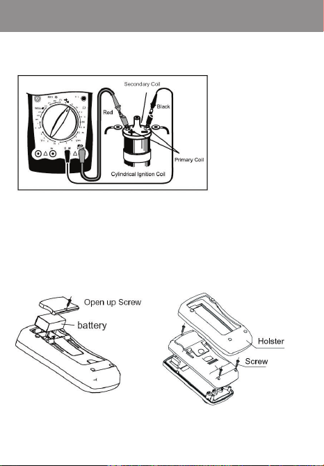
Fig 5. Ignition coil test
Fig 6. Replaceing the Battery Fig 7. Replace the fuse
manual_limit500auto.qxd 05-06-08 16.25 Sida 4
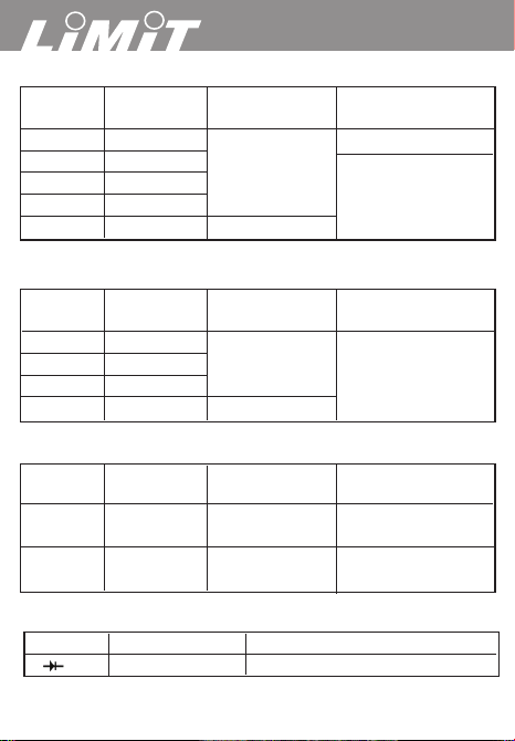
DC Voltage
Range Resolution Accuracy Overload
Protection
200mV 0.1mV 230V AC
2V 1mV ±(0,5%+1)
20V 10mV 1000V DC or 750
200V 100mV V AC continuous
1000V 1V ±(0,8%+5)
AC Voltage
Range Resolution Accuracy Overload
Protection
2V 1mV
20V 10mV ±(0.8%+5) 1000V DC or 750
200V 100mV V AC continuous
750V 1V ±(1.0%+4)
DC Current
Range Resolution Accuracy Overload
Protection
200mA 0.1mA ±(0.8%+5)
CE: Fuse 315mA, 250V,
fast type, 5x20 mm
10mA 10mA ±(1.2%+5)
CE: Fuse 10A, 250V,
fast type, 5x20 mm
Diodes Test
Range Resolution Overload Protection
1mV 600Vp
2
500
Auto
manual_limit500auto.qxd 05-06-08 16.25 Sida 5

Resistance
Range Resolution Accuracy Overload
Protection
200Ω0.1Ω
2kΩ1Ω600Vp
20kΩ10Ω±(0.8%+5)
200kΩ100kΩ
2MΩ1kΩ
20MΩ10MΩ±(1.5%+5)
Continuity test
Range Resolution Accuracy
1Ω600Vp
Dwell test
Range Resolution Accuracy Overload
Protection
4CYL
6CYL 0.1° ± (3%+5) 600Vp
8CYL
Tach (Rotation Speed) test
Range Resolution Accuracy Overload
Protection
4CYL
6CYL 10 RPM ± (3%+5) 600Vp
8CYL
3
Tabels
manual_limit500auto.qxd 05-06-08 16.25 Sida 6

4
Language page
English . . . . . . . . . . . . . . . . . . . . . . . . . . . . . . . .5-14
Svenska . . . . . . . . . . . . . . . . . . . . . . . . . . . . . .15-22
Norsk . . . . . . . . . . . . . . . . . . . . . . . . . . . . . . . .23-30
Dansk . . . . . . . . . . . . . . . . . . . . . . . . . . . . . . . .31-39
Suomi . . . . . . . . . . . . . . . . . . . . . . . . . . . . . . . .40-48
Deutsch . . . . . . . . . . . . . . . . . . . . . . . . . . . . . . .49-59
Nederlands . . . . . . . . . . . . . . . . . . . . . . . . . . . .60-69
Français . . . . . . . . . . . . . . . . . . . . . . . . . . . . . .70-79
Italiano . . . . . . . . . . . . . . . . . . . . . . . . . . . . . . .80-89
Español . . . . . . . . . . . . . . . . . . . . . . . . . . . . . . .90-99
Português . . . . . . . . . . . . . . . . . . . . . . . . . . .100-109
Polsku . . . . . . . . . . . . . . . . . . . . . . . . . . . . . .110-120
Eesti . . . . . . . . . . . . . . . . . . . . . . . . . . . . . . .121-128
Latviski . . . . . . . . . . . . . . . . . . . . . . . . . . . . .129-138
Lietuvi
Š
kai . . . . . . . . . . . . . . . . . . . . . . . .
139-149
Pyсский . . . . . . . . . . . . . . . . . . . . . . . . . . . .150-159
Language Contents
500
Auto
manual_limit500auto.qxd 05-06-08 16.25 Sida 7

5
English
Overview
General specification
Safety information
Voltage DC and AC
Current
Resistance
Diodes test
Continuity test
Dwell test
Engine tach/Rotation speed
Diagnosis test of fuses, switch, solenoid, relay etc.
Battery condition test
Battery consumption test
Battery charging test
Replace battery
Replace fuses
Contents
manual_limit500auto.qxd 05-06-08 16.25 Sida 8

Overview
This Operating Manual covers information on safety and cautions.
Please read the relevant information carefully and observe all the
Warnings and Notes strictly.
Limit 500 Auto are 3 1/2 digits multimeter, especially designed for
automotive troubleshooting but also for all kind of electrical measur-
ing. The display have large digits and also shows correct test leads
terminals and rotary switch position, makes this instrument easy to
handle for the user.
General Specifications
Measuring range and accuracy see page 2-3.
• Fused
µ
mA Input terminal: 0,5A, 250V fast type, 5x20 mm
• Fused 10 A Input terminal: 10 A, 250V fast type, 5x20 mm
• Range: Manual ranging
• Maximum Display: Display: 1999 or
3 1/2
digits.
•Measurement Speed: Updates 2-3 times /second.
• Temperature: Operating: 0°C~40°C (32°F~104°F).
Storage: -10°C~50°C (14°F~122°F).
•
Battery Type: One piece of 9V Battery NEDA 1604 or 6F22 or 006P.
•Safety/Compliances: IEC61010 CAT II 1000V, CAT III 600 V
over voltage and double insulation standard.
•Certification:
Safety Information
This Meter complies with the standards IEC61010: in pollution
degree 2, over voltage category (CAT II 1000V, CAT III 600V) and
double insulation.
Warning
To avoid possible electric shock or personal injury, and to
avoid possible damage to the Meter or to the equipment under
6
500
Auto
manual_limit500auto.qxd 05-06-08 16.25 Sida 9

7
English
test, adhere to the following rules.
•Before using the Meter inspect the case. Do not use the Meter if it
is damaged or the case (or part of the case) is removed. Look for
cracks or missing plastics. Pay attention to the insulation around
the connectors.
• Inspect the test leads for damages insulation or exposed metal.
Check the test leads for continuity.
• Do not apply more than the rated voltage, as marked on the
Meter, between the terminals or between any terminal and the
grounding.
• The rotary switch should be placed in the right position and no
any changeover of range shall be made during measurement is
conducted to prevent damage of the Meter.
• When the Meter working at an effective voltage over 60V in DC or
42V rms in AC, special care should be taken for there is danger of
electric shock.
• Do not use or store the Meter in an environment of high tempe-
rature; humidity, explosive, inflammable and strong magnetic
fields.
The performance of the Meter may deteriorate after dampened.
•
When using the test leads, keep your fingers behind the finger guards.
• Disconnect circuit power and discharge all high-voltage capacitors
before testing resistance, continuity, diodes and current.
• Before measuring current, check the Meter fuses and turn off
power to circuit before connecting the Meter to the circuit.
•Replace the battery as soon as the battery indicator appears. Whit
to low battery, the Meter might produce false readings that can
lead to electric shock and personal injury.
Functional buttons
Yellow • ON/OFF switch.
Hold • ON/OFF for hold function.
• H shows on the display when value is hold.
manual_limit500auto.qxd 05-06-08 16.25 Sida 10

8
Voltage measurement DC and AC (see fig 1)
1. Insert the red test lead into the VΩterminal and the black test
lead into the COM terminal.
2. Set the rotary switch to an appropriate measurement position in
V--range for DC or V~ for AC. When the value is unknown always
start from the max range 1000 V.
3. Connect the test leads across with the object being measured.
The measured value shows on the display.
Note
•Displays 1 selected range is overload; it is required to select a
higher range in order to obtain a correct reading.
•
In each range, the Meter has an input impedance of approx.10 MΩ.
This loading effect can cause measurement errors in high im-
pedance circuits. If the circuit impedance is less than or equal to
10kΩ, the error is negligible (0.1% or less).
Current measurement DC (see fig 2)
Warning
Never attempt an in-circuit current measurement where the voltage
between terminals and ground is greater than 250 V.
If the fuse burns out during measurement, the Meter may be damaged
or the operator himself may be hurt. Use proper terminals, function,
and range for the measurement.
When the testing leads are connect-ed to the current terminals, do
not parallel them across any circuit.
Measuring time for current should be less than 10 sec and interval
between measurement should be at least 15 minutes.
To measure current, connect as follows:
1.
Turn off power to the circuit. Discharge all high-voltage capacitors.
2. Insert the red test lead into the A or mA terminal and the black
test lead into the COM terminal.
500
Auto
manual_limit500auto.qxd 05-06-08 16.25 Sida 11

9
English
3. Set the rotary switch to an appropriate measurement position A
... range for DC or A~ for AC. When the value is unknown
always start from the max range 10 A.
4. Break the current path to be tested. Connect the red test lead to
the more positive side of the break and the black test lead to the
more negative side of the break.
5. Turn on power to the circuit. The measured value shows on the
display.
Note
• Displays 1 selected range is overload, it is required to select a
higher range in order to obtain a correct reading.
Resistance measurement (see fig 3)
1. Insert the red test lead into the VΩterminal and the black test
lead into the COM terminal.
2. Set the rotary switch to an appropriate measurement position in
Ωrange.
3. Connect the test leads across with the object being measured.
The measured value shows on the display.
Note
• Displays 1 selected range is overload, or the circuit is open.
•
The test leads can add 0.1Ωto 0.3Ωof error to resistance measure-
ment. To obtain precision readings in low-resistance measurement,
that is the range of 200Ω, short-circuit the input terminals before-
hand and record the reading obtained. This is the additional
resistance from the test lead.
Diode test (see fig 3)
Use the diode test to check diodes, transistors, and other semicon-
ductor devices. The diode test sends a current through the semicon-
ductor junction, and then measures the voltage drop across the
junction.
manual_limit500auto.qxd 05-06-08 16.25 Sida 12

10
Agood silicon junction drops between 0.5V and 0.8V.
To test a diode out of a circuit, connect as follows:
1. Insert the red test lead into the VΩterminal and the black test
lead into the COM terminal.
2. Set the rotary switch to diode position.
3. For forward voltage drop readings on any semiconductor compo-
nent, place the red test lead on the component’s anode and
place the black test lead on the component’s cathode.
The measured value shows on the display.
Continuity test (see fig 3)
To test for continuity Testing voltage is 2,7 V.
1. Insert the red test lead into the VΩterminal and the black test
lead into the COM terminal.
2. Set the rotary switch to continuity position.
3. Connect the test leads across with the object being measured.
The buzzer sounds if the resistance of a circuit under test is less
than 30Ω.
Dwell test (See fig 4)
For older cars it was important to test the dwell of the cut-off switch
of an ignition system. Dwell testing means the duration when the
cut-off switch remains off when the cam is turning.
1. Set the rotary switch to Dwell position and correct numbers of
cylinders.
2. Insert the red test lead into the V_Dwell terminal and the black
test lead into the COM terminal.
3. Connect the red test lead to the ignition coil and the black test
lead to ground as fig 4.
4. Read the ignition dwell on the display.
500
Auto
manual_limit500auto.qxd 05-06-08 16.25 Sida 13

11
Engine tach / Rotation speed (See fig 4)
1. Set the rotary switch to RPMx10 position and correct numbers of
cylinders.
2. SInsert the red test lead into the V_RPM terminal and the black
test lead into the COM terminal.
3. Connect the red test lead to the ignition coil and the black test
lead to ground as fig 4.
4. Start the engine and read the rotation speed on the display. The
reading must be multiplied by 10.
For example, actual rotation speed is 2350 RPM, the display shows 235.
Test of switches, fuses, solenoid, relay etc.
1. Set the rotary switch to 200 Ω.
2. Insert the red test lead into the Ωterminal and the black test lead
into the COM terminal.
3. Short circuit the red and black test leads. The display should
show 0,2 to 0,5 Ω.
4.
Connect the test leads parallel to the component which would be tested.
The impedance of most solenoids and relays is less than 200 Ω.
Fuses and switches have impedance around 10 Ωor less. Displays
1, the component is cut off or the rotary switch is in incorrect position.
Ignition coil test (see fig 5)
Before testing the engine must be cold and cut off the ignition coil.
1. Set the rotary switch to 200 Ω.
2. Insert the red test lead into the Ωterminal and the black test lead
into the COM terminal.
3. Short circuit the red and black test leads. The display should
show 0,2 to 0,5 Ω.
4. Connect the red test lead to the ignition coils primary + pole and
the black test leads to the primary - pole as fig 5. The resistance
should be less than 0,5 Ω.
English
manual_limit500auto.qxd 05-06-08 16.25 Sida 14

12
5. Set the rotary switch to 200 kΩ.
6. Connect the red test lead to the secondary outlet and the black
test leads to the primary - pole as fig 5.
The secondary outlet is generally in range 6 kΩto 30 kΩ. Refer to
various kind of automotives manuals.
Battery condition test
Test if battery is fully charged.
1. Set the rotary switch to 20 VDC position.
2. Insert the red test lead into the V terminal and the black test lead
into the COM terminal.
3. Turn off the ignition switch.
4. Turn on the driving lights for 10 sec. to release charges from the
battery.
5. Connect the black test lead to the battery negative pole and the
red to the positive pole.
The testing result are shown in contrast as follows. 12,6V-100%.
12,45V-75%. 12,3V-50%. 12,15V-25%.
Battery consumption test when the engine is off
The test is useful for determination of the additional consumption of
the battery.
1. Turn off ignition key and make sure lights etc are closed.
2. Set the rotary switch to 10A position.
3. Insert the red test lead into the A terminal and the black test lead
into the COM terminal.
4. Cut off the cable to the battery positive pole and connect the red
test lead to the battery positive pole and the black test lead to the
cable. The measured value shows on the display.
Power consumption to a frequent-modulated radio or clock needs a
current supply of 100 mA. If there emerges any additional current do
necessary service.
500
Auto
manual_limit500auto.qxd 05-06-08 16.25 Sida 15

13
English
Note
• Do not start the engine during test, or the instrument will be
damaged.
Battery charging test
For testing if the charging system operates normally.
1. Set the rotary switch to 20 VDC position.
2. Insert the red test lead into the V terminal and the black test lead
into the COM terminal.
3. Connect the black test lead to the battery negative pole and the
red to the positive pole.
4. Run the engine idle and close or turn off accessories as light, fan,
radio etc. Voltage would be 13,2 V to 15,2 V.
5. Open the throttle to 1800 RPM to 2800 RPM. The voltage would
increase max 0,5 V.
6. Turn on driving lights, fan, windscreen wipers etc. and increase
the loads of the electric system. The voltage would not be less
than 13,0 V if the charging system works properly.
Replacing the Battery (see fig 6)
1. Disconnect the connection between the testing leads and the
circuit under test when battery indicator appears on the display.
2. Turn the Meter to OFF position.
3.
Remove the screw, and separate the case bottom from the case top.
4. Replace the battery with a new 9V battery (NEDA 1604 or 6F22
or 006P).
5. Rejoin the case bottom and case top, and reinstall the screw.
Replace the fuse (see fig 7)
1. Disconnect the connection between the testing leads and the
circuit under test.
2. Turn the Meter to OFF position.
manual_limit500auto.qxd 05-06-08 16.25 Sida 16

500
Auto
14
3.
Remove the screw and separate the case bottom from the case top.
4. Replace only fuses with the identical type and specification as
follows. 315 mA, 250V, fast type, 5x20mm or 10 A, 250 V, fast
type 5x20 mm.
5. Rejoin the case bottom and case top, and reinstall the screw.
Replacement of the fuses is seldom required. Burning of a fuse
always results from improper operation.
manual_limit500auto.qxd 05-06-08 16.25 Sida 17

Svenska
15
Allmänt
Specifikationer
Säkerhetsföreskrifter
Spänningsmätning DC och AC
Strömstyrka DC
Resistansmätning
Diodtest
Kontinuitetstest
Kamvinkelmätning
Varvtalsmätning
Test av relä, magnetspole, säkringar, brytare
Batteritest
Batteribelastningstest
Batteriladdningstest
Batteribyte
Säkringar
Innehåll
manual_limit500auto.qxd 05-06-08 16.25 Sida 18

Allmänt
Denna bruksanvisning innehåller information om säkerhet och
handhavande. Läs noggrant igenom och observera alla varningar
och säkerhetsföreskrifter.
Limit 500 Auto är en speciellt anpassad multimeter för dig som
arbetar med bilmotorer, båtmotorer etc. För mätning, justering,
kontroll och felsökning.
Tydlig display med stora siffror som också visar också korrekt test-
kabelanslutning samt valt mätområde, vilket gör instrumentet enkelt
och tillförlitligt för användaren.
Specifikationer
Mätområden och noggrannhet se sid 2-3.
•
µ
mA anslutningen är säkrad : 315 mA, 250 V, Snabb, 5x20 mm.
• 10A anslutningen är säkrad : 10 A, 250 V, Snabb, 5x20 mm.
• Manuellt områdesval.
• Displayen visar korrekt testkabelanslutning samt valt mätområde.
• Display
3 1/2
siffra eller 1999.
• Mäthastighet 2-3 gånger per sek.
• Temperatur. Arbetstemperatur 0 – 40ºC.
Förvaringstemperatur – 10 - 50ºC.
• Batteri. 1 st. 9 V standardbatteri typ 6F22.
• Säkerhet enligt IEC61010 CAT II 1000V/ CAT III 600 V.
Certifikat CE.
Säkerhetsföreskrifter
Detta instrument uppfyller standard enligt IEC61010, Isolation CAT II
1000 V, CAT III 600 V.
Varning
Att undvika elektriska chocker eller personliga skador läs
säkerhetsföreskrifterna och ta del av nedanstående regler
16
500
Auto
manual_limit500auto.qxd 05-06-08 16.25 Sida 19

Svenska
17
innan ni tar instrumentet i bruk.
•
Kontrollera att instrumentet är oskadat och inga sprickor finns i höljet.
Kontrollera speciellt isolationen kring testkabelanslutningarna.
•
Kontrollera att testkablarna är oskadade.
•
Anslut inte till högre spänning än instrumentet är märkt för mellan
kopplingsanslutningarna eller mellan fas och jord.
•
Vridomkopplaren skall vara inställd på korrekt position och skall inte
ändras under pågående mätning.
•
När instrumentet mäter en effektiv spänning över 60 V DC eller 42 V
AC skall extra försiktighet iakttas.
•
Förvara inte instrumentet där det kan utsättas för hög temperatur, hög
luftfuktighet, explosionsrisk eller kraftiga magnetiska fält.
•
Håll fingrar bakom skyddet på testkablarna.
•
Bryt strömmen före mätning av motstånd, kontinuitet, dioder eller
strömstyrka.
•
Före mätning av strömstyrka, kontrollera instrumentets säkringar och
bryt strömmen före anslutning av instrumentet till kretsen.
•
Byt batteri så fort batteriindikatorn på displayen visas.
Funktionsknappar
Gul knapp • På/av knapp för instrumentet.
Hold • På/av knapp för holdfunktionen. H visas på
displayen när mätvärdet är låst.
Spänningsmätning DC och AC (Se fig 1)
1. Sätt den röda testkabeln i VΩ-anslutningen och den svarta
testkabeln i COM-anslutningen.
2. Sätt vridkopplaren på önskat V ... läge för likström eller V~läge
för växelström. Börja alltid på högsta värdet när mätområdet
är okänt.
3. Anslut testkablarna till mätobjektet. Mätvärdet visas på displayen.
manual_limit500auto.qxd 05-06-08 16.25 Sida 20
Other manuals for 500 Auto
1
Table of contents
Languages:
Other LIMIT Multimeter manuals
Popular Multimeter manuals by other brands

Unit
Unit UT501 operating manual

Kyoritsu Electrical Instruments Works, Ltd.
Kyoritsu Electrical Instruments Works, Ltd. 6010A instruction manual

Pro's Kit
Pro's Kit mt-1232 user manual

Digi-Sense
Digi-Sense 20250-50 user manual

EGAmaster
EGAmaster EGAtronik 51255 operating instructions

Unit
Unit UT51 operating manual