manuals.online logo
Brands
  1. Home
  2. •
  3. Brands
  4. •
  5. Lince
  6. •
  7. Security Sensor
  8. •
  9. Lince Bobby User manual

Lince Bobby User manual

1
REG. N. 4796
UNI EN ISO 9001:2000
________________________________________________________________
_____________________________________________
TECHNICAL MANUAL
_____________________ MADE IN ITALY ___________________
Art 1673
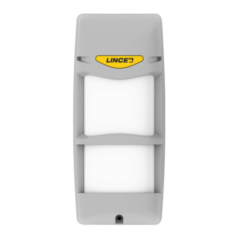
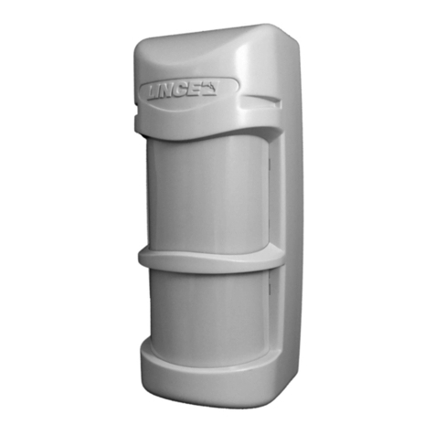
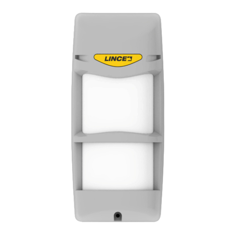
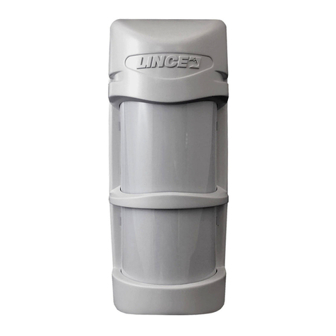
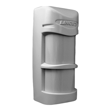
     / Triple technology outdoor detector
2

SUMMARY
/PAGE

Technical features
2

Description
3 - 4

Notices
4

Detection Area choice
4 - 5

Parts identification
6 -7

Installation
7- 8 -9

Wiring
10
LED 
Visualization LED
10
 PIR
Lower PIR adjustment
11 -12
 MW
MW range adjustment
13
 DIP Switches
DIP switches setting chart
13
 AND
AND mode
14
 OR
OR mode
15

Wrong installation examples
16 -17

Troubleshooting
20
 
TECNICAL FEATURES
, 
.
 PIR 
MW 
 MW: 10,525 GHz.
  
,  
 UV.

 ().
 Fresnel 
 UV.
: .
 +/- .
polycarbonate 
 UV.
    .
, 
(
).
 IP44.
.
.
 :-CC.
: 3 .
 11 ~ 15 Vcc.
: 25 mA.
 AND OR, .
: 81x56x189 mm.
Triple technology for outdoor use.
Two PIR sensors and one microwave with
switching function.
MW frequency 10.525 GHz.
Infrared sensors low consumption double
element and UV filter.
Fine adjustment of the lower beam (patented
system).
UV rays resistant Fresnel Lens.
.
Horizontal detection excursion + / - .
UV resistant polycarbonate case.
Stainless steel wall fixing bracket.
Stainless steel pole fixing brackets (available
on request).
Protection IP44.
Antimasking function.
Adjustable IR sensibility.
Operating temperature: -C C.
Operating range: 3 
Power supply from 11 to 15 Vdc.
Power consumption: 25mA.
AND/OR selectable function.
Dimensions: 81x56x189 mm.
3

DESCRIPTION
O    BOBBY
    -
    -
    0,525GHz. 
     
     
      -
.  3    -
     
    -
     
 3m  15m.
 BOBBY  
.
   
    -
  .
   
    
     -
  (  5~10
cm   .
 :
  DIP switch    
ON.
     
LED 30 
    
  30   
LED 
,      LED 
   30 -
     -


     
    -
     
-

      
LEDs     
-.
    
     15
    
 FAULT.
The BOBBY outdoor detector consists of two
dual PIR passive sensors and a 10,525GHz
microwave. The particularly evolved electronics
has been designed to guarantee the maximum
performances in external and rigid temperatures
environment. The three beams are adjustable
and allow getting a horizontal coverage

The lower infrared beam is even vertically
adjustable and it allows getting a detection
range between 3m and 15m.
Besides the alarm functions, the detector is
provided with ANTIMASKING functions
ANTIMASKING function has been implemented
to make the Bobby detector mostly unassailable
from those, who could have access to the site
where the sensor is installed, during the period
in which the system of alarm results disabled,
therefore in order to signalling attempts

The detector is able to notice attempts of
microwave obscuring with metallic or great
dimensions not metallic objects. 
to the detector).
Antimasking activation:
.
When this function is activated the blue LED get
blinking for 30 sec. Close the cover during the
blinking.
Then yellow and blue LED will blink
simultaneously for 30 s indicating that the
sensor is sampling the microwave reflection.
It is important that during the initialization no
obstacles or persons are closer than 1 meter to
the sensor. The cover must be in closed
position.
will return
to their normal function.
If the detector is blinded by a metallic object for
more than 15 s it indicates the masking and the
FAULT relay get opened.
At the first event of alarm the relay goes back to
4

 Relay     
 (NC).
O    -
     -


the default status (NC).
If Bobby is installed as a part of a Lince alarm
system, might be useful connect the fault output
to a SMS manager input (ex. Telephone dialler
GSM) .
It is not recommended to connect this output to
an alarm input.

NOTICES
     -
  3~4   -
     -
  .
    
     
 .
 30~40   
    
   .
  .  -
     LED.
     ~8


     
.
    
, .
After having turned on the detector, wait at
le
range in order to let the PIR become stable.
To get a real simulation, verify that the
protected area is free from obstacles in
movement.
Wait 30-40 seconds and try to enter in the
protected area. Pay attention to across the
beams.
Verify whether the detector works properly
checking if the blue LED gets on after motion
detection.
After the first alarm it must wait about 7- 8
seconds before to cause a new detection.
During the test, pay attention to across the
beams orthogonally (see Fig1)
The detection diagram is shown in fig.1 in next
page.

DETECTION AREA CHOICE
    15
 (   120cm) 

    
AND OR,     
  ( 
).
 AND:   , 
     
     
    
     -
    
     -
.
The maximum detection range is 15 m (at 120
cm from the ground) with covered area of

The detector can work both in AND or in OR
configuration for PIRs. (the microwave is
always on).
AND mode: In this configuration only the
simultaneous interruption of the two infrared
beams and the activation of the MW produce
an alarm. This setting is recommended in
outdoor environments and in presence of small
animals.
5
 OR:  , -
    
     -
   
  DIP switches   -
 
13, 14 & 15).
 OR   
    
     
.
OR mode: In this configuration the mana-
gement of the beams is separate; the possible
configurations are described in the paragraph
of setting out the DIP switch and relative
examples of installation. (page13, page14,
page15)
OR mode is not recommended in
completely outdoor environments and in
presence of small animals.
 ()
COVERED AREA PATTERN (PLAN VIEW)

  
Grey zones cannot be protected; the coverage of dashed zones can be obtained with rotation
of internal mechanism.
 1
Figure 1
6
  / PARTS IDENTIFICATION


Identification
A

Detector on wall fixing screws
B

Cover fixing screw
C
 Fresnel
Cover with Fresnel lens
D

PIR2
Adjusting knob for low PIR2
E
    
ntally rotating device
F
Tamper (
 A)
Antitamper micro switch (only if fixed with screw
A)
G
    (
 
Stainless steel wall fixing bracket
H
    )
( , 
. 001805/00102AA)

(ot supplied, available in kit 001805/00102AA)
I
 M4 x 6 
 ) -
( , 
 001805/00102AA)

brackets fixing (4pcs )
(Enclosed into kit item 001805/00102AA)
L
 M4 x 10 (4
)
( , 
. 001805/00102AA)
Stainless Steel metric screw M4 x 10
(Enclosed into kit item 001805/00102AA)
    (G)
 (A).
Tamper,

.


Fix the detector to the support (G) using the
two screws (A).
In particular, the mounting screw, close to
the micro switch, ensures, also the anti
tamper protection.
Do not touch the filter lenses on the

 1 / Table 1
 3
Figure 3
7

INSTALLATION
      
1 , 
.
     
 ,    
,    
      
 .
   B   

    
   A, (
8).    
 7.
   PIR 2 (),
   
  ,    
  (  12 
13).   trimmer  
    -
  ( 14).
     
   (B) ( 9).
Installation height must be between 1m and
1.30m (not tilted ground )
Important: if there is a medium size pet around
the detection area, please adjust installation
height as shown in the page 16
Fix the support on a wall or on a stable pole
Unscrew the (B) screw an remove the
front cover with lens.
Screw up the detector on the support
using the 2 provided screws (A) (see
fig 8) passing through the connection
cable as shown in the figures: fig 5 fig
6 fig 7
Lift up or take down the PIR 2 (lower)
using the adjusting knob to choose the
protected area as shown in fig 12 and
fig13
oRotate the trimmer to adjust the MW
sensibility.(see fig 14)
Mount the front cover fixing it with
screw (B) (see fig 9)
:    (15m) 
 120 cm.
Important: The maximum detection range (15 meters) is obtained only if the installation
height is 120 cm.
120 cm
 4
Figure 4
8
        .   
, ,        .
      fresnel   .  
   .
Avoid directing the detector towards moving objects or, if impossible, please take care in
adjusting the detector in order to avoid false alarms.
Be sure to install the cover with Fresnel lens before the detector testing.
Without cover, the detector .

ASSEMBLY SEQUENCE
 4   

    
  



 7.
Make four holes on the wall and
insert the plugs.
Pass the wires through the
support slot and fix the metallic
support on the wall.
To fix the metallic support on
the pole, please see fig.7


.
Fix the metallic support on the
wall perpendicularly to the
ground.
 5
Figure 5
6
Figure 6
9
    
 
  
  
  
 U
(
Fix the support onto the
mounting support with
supplied screws.
Place the brackets (not
included) around the pole
and fasten using the pole
locking screws.
   
  
  
    
   
  .
Locate the detector body on
the metallic support and slide
it down, then fix it using the
supplied screws.
   PIR
2  MW,  
   
 


Adjust PIR2 and MW, close
the detector inserting
downwards the coverage as
shown in figure.
Fix the cover using the
metric screw.
 7
Figure 7
 8
Figure 8
 9
Figure 9
    



Perforate the cable passage
knockout using a sharp
point tool, as a screwdriver
or similar.
10
 / LECTRIC WIRING
 LEDs INDICATION LEDs


Color
Function
LED 1 (Μπλε)
LED  
LED 1 (Blue)
General alarm LED
LED 2
(Κίτρινο)
LED 

LED 2 (Yellow)
Microwave LED
LED 3
(Πράσινο)
LED  
PIR
LED 3 (Green)
Upper PIR LED
LED 4
(Πράσινο)
LED  
PIR
LED 4 (Green)
Lower PIR LED
 2 / Table 2
Fig 10
 11
Figure 11
.
Antimasking output: To transmit technical alarm
 12 Vcc (10 ~ 15 Vcc)
Power 12 Vdc (10 ~ 15 Vdc)
Tamper 24
24 h Antitamper output
: NC 
Alarm output: normally closed relay in stand by
11
 PIR 2
PIR 2 ADJUSTMENT
 PIR 2 

cm.

PIR 2.
PIR2 adjustment through adjusting knob.
Installation height 120 cm
Position adjustment related to different lower
PIR 2 range.
 E / Position E
 D / Position D
3 m 4 m 7 m 11 m 15 m
120 cm
3 m 4 m 7 m 11 m 15 m
120 cm
 12
Figure 12
12
3 m 4 m 7 m 11 m 15 m
 C / Position C
 B / Position B
 A / Position A
       (.. ),    
     15 .
 AND (Dip 3  4  OFF), 
PIR 2 ().
If the object in motion is very large (for example a car) there is possibility that the detector can detect
its presence  15m.
If the detector is set in triple AND (Dip 3 and 4 in OFF position) configuration, the maximum distance
of detection is the one setted through the Adjustment of the PIR 2
3 m 4 m 7 m 11 m 15 m
120 cm
120 cm
120 cm
 13
13
MW
MW RANGE ADJUSTMENT
14 / Figure 14


Adjust the microwave sensibility in relationship to the needed detection range.
DIP SWITCHES  JUMPER
DIP SWITCHES AND JUMPER SETTINGS
Dip 1
Off
 OFF
Dip 1
Off
ANTIMASKING
OFF
Dip 1
On

ON
Dip 1
On
ANTIMASKING ON
Dip 2
Off

 IR
Dip 2
Off
IR sensitivity low
Dip 2
On

IR
Dip 2
On
IR sensitivity high
Dip 3
Dip 4
Off
Off
 +
PIR1 + PIR2
Dip 3
Dip 4
Off
Off
Microwave and
PIR1 & PIR2
Dip 3
Dip 4
Off
On
+
PIR2
(PIR1 )
Dip 3
Dip 4
Off
On
Microwave and
PIR1
(PIR2 disabled)
Dip 3
Dip 4
On
Off
 +
PIR1 (PIR2
)
Dip 3
Dip 4
On
Off
Microwave and
PIR2
(PIR1 disabled)
Dip 3
Dip 4
On
On
 +
 OR
 PIR 1
 PIR 2
Dip 3
Dip 4
On
On
Microwave and the
OR function
between PIR and
PIR2
Jumper
J1

LED 
Jumper
J1
Plugged
LEDs enabled
Jumper
J1

LED 
Jumper
J1
Unplugged
LEDs disabled
     
11     
DIP switches  J1

.
Refer to the following chart and to the fig.11 for
dip switches and jumper J1 set up.
14
AND
AND MODE OPERATION

 AND (Dip 3  4  OFF)
1. 
     2
  3 PIR  MW).

2. 
    2
 3 PIR  MW).
.
3 
     3
 (PIR 1+ PIR 2 + MW).
.

AND
DIP switches 



Warning: the examples are referred to the
triple AND set up. In case of different set up
(see DIP Switches 3 and 4 in ON position
page 17) alarms are enabled also in the
previous examples (1 and 2).
Example of detection in triple AND
configuration
(Dip 3 and 4 in OFF position)
1. NO ALARM
The pet is detected only by two of the three
sensor elements (PIR low and MW).
The alarm is not enabled.
2. NO ALARM
The body is detected only by two of the
three sensor elements (PIR high and MW).
The alarm is not enabled.
3 ALARM
The body is detected by the three sensor
elements (PIR 1+PIR 2+MW).
The alarm is enabled
15
 OR
OR MODE OPERATION
DIP Switch
DIP 3 OFF
DIP 4 ON
 + PIR2 (
PIR 1 )
MW + PIR 2 ( PIR 1 is
disabled)
    DIP switches, 
  ,  PIR 1 ()
     
PIR 2 () 
 .


Setting up the DIP as shown in the table, PIR 1
(high) is excluded, and then the alarm will be
enabled only when PIR 2 (lower) and
microwave will detect an intrusion.
This set up is not recommended in completely
external environment
DIP Switch
DIP 3 ON
DIP 4 OFF
 + PIR 1
(PIR2 )
MW + PIR 1
(PIR 2 is disabled)
    DIP switches, 
  ,  PIR 2 ()
     
PIR 1 () 
.


Setting up the DIP as shown in the table, PIR
2 (lower) is excluded, then the alarm will be
enabled only when PIR 1 (high) and
microwave will detect an intrusion.
This set up is not recommended in completely
external environment
DIP Switch
DIP 3 ON
DIP 4 ON
 +
PIR 1 PIR 2
MW + PIR 1 or PIR 2
    DIP switches 
   , 
  
    
PIR PIR 2.

o
Setting up the DIP as shown in the table, the
alarm is enabled when the microwave and one
of the two PIRs (regardless of which of the
two) detect an intrusion.
This set up is not recommended in completely
external environment
16

 

CORRECT INSTALLATION
Position the detector vertically and
perpendicularly to the ground

()
    
    ,  
   .
WRONG INSTALLATION
(detector tilted downwards)
If the detector is not installed
perpendicularly to the ground, as shown,
operational reliability may result
decreased.

X
17


()
    
    ,  
   .
WRONG INSTALLATION
(detector tilted upwards)
If the detector is not installed perpendicularly to
the ground, as shown, operational reliability
may result decreased.
 



NOT CORRECT MOUNTING
Take care to install the detector
perpendicularly to the ground.
X
18
 Bobby   
     
.  , 
     
   



Bobby is designed to avoid any light
disturbance. However too strong light as direct
sunlight may cause unstable condition of
detector, for example direct sunlight.

installation.
:
Installing constraints:
     
    
 .    
   1m  
      
     
 10 .    
   130 cm,  
    
   .
The detector installation height is a
fundamental factor for its correct
operation. If the installation height is
smaller than 1m it is possible that small
animals can be detected and the
maximum detection area is less than ten
meters; if the installation height is greater
than 130 cm, there will be a great not
protected area in the down portion of the
detection range.
19



 LEDs 

9.5  16 Vdc)
jumper


       PIR 
    


MW 


PIR 
 MW 
   
 FAULT


TROUBLE SHOOTING
Trouble
Solution
LEDs inactive
Check wiring connection
Check the presence of current and if the voltage is between 9.5 and 16
Vdc
Check if the jumper j1 is set or not
Make alarm even though no
moving objet is in the area
(false alarms)
The detector is not perpendicular to the ground
Check if the lower detection area is wider than your planning
Check if there are objects in movement in the detection area.
MW adjustment is set at maximum level
No detection, sometimes.
The Lower PIR is not properly adjusted
MW adjustment is set at minimum level
Continuous alarm from FAULT
output
Check if there are any object around the detector
Check if there are metallic objects around the detector
20
www.sigmasec.gr

Other manuals for Bobby

2

This manual suits for next models

1

Other Lince Security Sensor manuals

Lince BABY UNIVERSALE User manual

Lince

Lince BABY UNIVERSALE User manual

Lince BABY User manual

Lince

Lince BABY User manual

Lince 4059GR868ZENITH User manual

Lince

Lince 4059GR868ZENITH User manual

Lince 9528-GOLD-TP-L User manual

Lince

Lince 9528-GOLD-TP-L User manual

Lince Bobby User manual

Lince

Lince Bobby User manual

Lince 1673BOBBY User manual

Lince

Lince 1673BOBBY User manual

Lince DTP 20 User manual

Lince

Lince DTP 20 User manual

Lince GR868DT User manual

Lince

Lince GR868DT User manual

Lince 1486DTP20 User manual

Lince

Lince 1486DTP20 User manual

Lince BOBBY-AM/E User manual

Lince

Lince BOBBY-AM/E User manual

Lince ZENITH GOLD 869 Series User manual

Lince

Lince ZENITH GOLD 869 Series User manual

Lince BABY WIRELESS GR868 User manual

Lince

Lince BABY WIRELESS GR868 User manual

Lince DTP 100 User manual

Lince

Lince DTP 100 User manual

Lince Bobby Universale User manual

Lince

Lince Bobby Universale User manual

Lince OBLO'/E User manual

Lince

Lince OBLO'/E User manual

Lince GR868 Bobby User manual

Lince

Lince GR868 Bobby User manual

Lince ZENITH GOLD 869 Series User manual

Lince

Lince ZENITH GOLD 869 Series User manual

Lince BOBBY GOLD Series User manual

Lince

Lince BOBBY GOLD Series User manual

Lince JOLLY User manual

Lince

Lince JOLLY User manual

Lince Sigma 1946-BOBBY180-24-AM-V User manual

Lince

Lince Sigma 1946-BOBBY180-24-AM-V User manual

Lince 1906-BOBBY-T-E User manual

Lince

Lince 1906-BOBBY-T-E User manual

Lince 1883 ZENITH DT/E User manual

Lince

Lince 1883 ZENITH DT/E User manual

Lince BOBBY-AM User manual

Lince

Lince BOBBY-AM User manual

Lince 1866BABY-BA/E User manual

Lince

Lince 1866BABY-BA/E User manual

Popular Security Sensor manuals by other brands

Theben compact office EIB installation manual

Theben

Theben compact office EIB installation manual

RectorSeal AQUAGUARD 4200E installation instructions

RectorSeal

RectorSeal AQUAGUARD 4200E installation instructions

Risco ViTRON RWT6G installation instructions

Risco

Risco ViTRON RWT6G installation instructions

Aritech DDI602AM Installation sheet

Aritech

Aritech DDI602AM Installation sheet

TH COMMUNICATIONS DoorProtect user manual

TH COMMUNICATIONS

TH COMMUNICATIONS DoorProtect user manual

Leuze electronic OPSL 775 manual

Leuze electronic

Leuze electronic OPSL 775 manual

3M 8511 User instructions

3M

3M 8511 User instructions

System Sensor 4451HT Installation and maintenance  instruction

System Sensor

System Sensor 4451HT Installation and maintenance instruction

Elko iNels DMD3-1 manual

Elko

Elko iNels DMD3-1 manual

MUELLER CO. 107 Series instructions

MUELLER CO.

MUELLER CO. 107 Series instructions

ABB IR/KB Technical data

ABB

ABB IR/KB Technical data

Latchways R20 Usage Guide

Latchways

Latchways R20 Usage Guide

Orisec IR-100 user manual

Orisec

Orisec IR-100 user manual

Satel abax 2 ADD-200 manual

Satel

Satel abax 2 ADD-200 manual

Varian 380-LC Service manual

Varian

Varian 380-LC Service manual

Nortech PD230 Enhanced Vehicle Detector user manual

Nortech

Nortech PD230 Enhanced Vehicle Detector user manual

Basalte AURO 0180-02 installation manual

Basalte

Basalte AURO 0180-02 installation manual

TeraBee Air Quality SB5 quick start guide

TeraBee

TeraBee Air Quality SB5 quick start guide

manuals.online logo
manuals.online logoBrands
  • About & Mission
  • Contact us
  • Privacy Policy
  • Terms and Conditions

Copyright 2025 Manuals.Online. All Rights Reserved.