manuals.online logo
Brands
  1. Home
  2. •
  3. Brands
  4. •
  5. Elko
  6. •
  7. Security Sensor
  8. •
  9. Elko iNels DMD3-1 User manual

Elko iNels DMD3-1 User manual

DMD3-1
1/2
110°
+
-
BUS
BUS
BUS +
BUS -
DALI
DALI
RUN SET
140°
4 m
4 m
Combined detector
EN
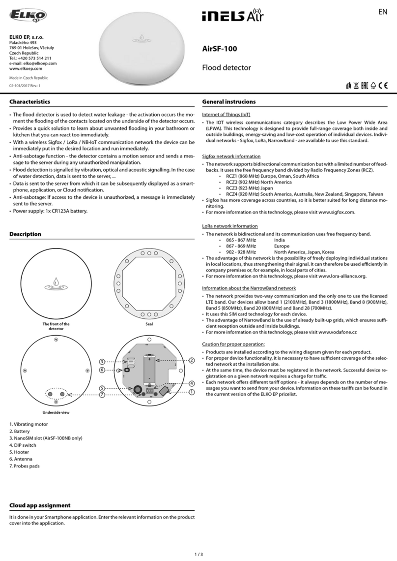
Characteristics
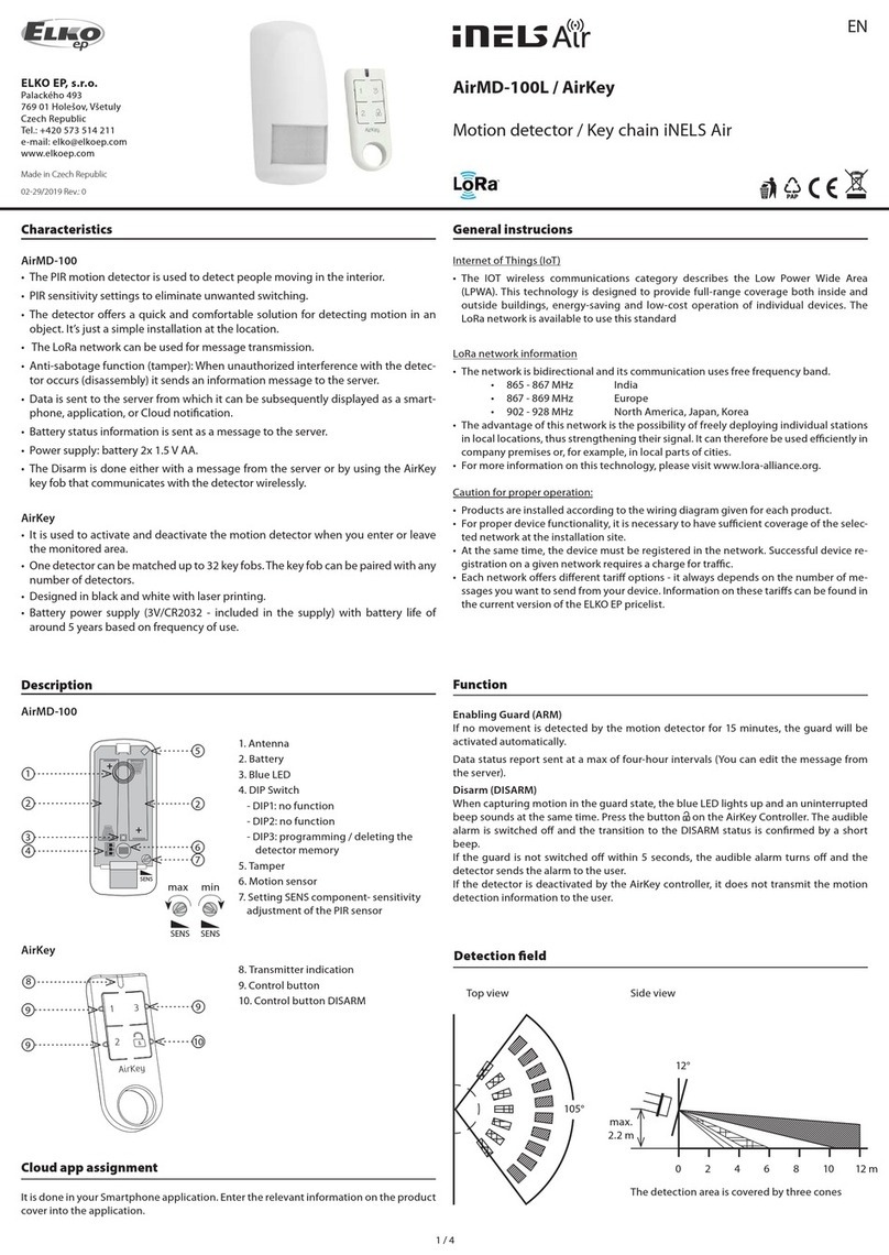
• DMD3-1 is a combined detector for ceiling mounting.
• DMD3-1 can be used in two basic ways:
- Motion detector
- Sensor luminescence
• The unit is equipped with two communication interfaces:
- Installation iNELS BUS
- DALI
• The motion detector is used to detect people moving in the area. Using the passive scanning
infrared spectrum for detection.
• Integrated luminescence sensor can be used for sensing current luminescence at the point of
installation of the unit. This information can be used in tasks to maintain a constant luminescence.
In space where it is possible, thanks to the contribution of natural light from the outside to adjust
the artifi cial light, which can reduce energy consumption.
• Setting the communication interface is done using the SET button.
• The unit can be configured via the iNELS3 Designer & Manager software, which, among other
things it is possible to:
- Set the desired function depending on detected motion.
- Resolve jobs based on the value of luminescence.
- Enable / disable the alarm LED on the detector housing.
• DMD3-1 detector is designed for indoor installation and is not intended for outdoor use.
• DMD3-1 detector is powered directly via the iNELS BUS installation (nominal 27 V DC) or DALI BUS
(nominal 16 V DC).
General instrucions
CONNECTION TO THE SYSTEM, INSTALLATION BUS
iNELS3 peripheral units are connected to the system through the BUS installation. Installation
BUS conductors are connected to the terminal units to BUS + and BUS-terminals, wires cannot be
interchanged. For installation of BUS it is necessary to use a cable with a twisted pair of wires with
a diameter of at least 0.8 mm, the recommended cable is iNELS BUS Cable, whose features best
meet the requirements of the BUS installation. Bearing in mind that in terms of all the properties
iit is it is possible in most cases also use the cable JYSTY 1x2x0.8 or JYSTY 2x2x0.8, however it is not
recommended as the best option. In the case of a cable with two pairs of twisted wires it is not possible
to use the second pair of the other for modulated signal due to the speed of communications; it is
not possible within one cable to use one pair for one segment BUS and the second pair for the
second segment BUS. For installation of BUS it is vital to ensure that it is kept at a distance from the
power lines of at least 30 cm and must be installed in accordance with its mechanical properties.
To increase mechanical resistance of cables we recommend installation into a conduit of suitable
diameter. Topology installation of BUS is free except for a circle, each end of the BUS must terminate
at terminals BUS + and BUS-. While maintaining all the above requirements, the maximum length
of one segment of the installation BUS can reach up to 550 m. Due to the data communication
and supply of units in one pair of wires, it is necessary to keep in mind the diameter of wires with
regards to voltage loss on the lead and the maximum current drawn. The maximum length of the
BUS applies provided that they comply with the tolerance of the supply voltage.
For the management of DALI BUS there is not an exact cable type recommended, but it is important
to keep some installation conditions. For DALI BUS lines up to 100 m the recommended min.
conductor cross section is 0.5 mm2. For management between 100 m -150 m a cross section of 0.75
mm2and more than 150 m the recommended min is 1.5 mm2. Management of more than 300 m
is not recommended. The voltage drop at the end of the installation may not be greater than 2 V.
CAPACITY AND CENTRAL UNIT
It is possible to connect to the central unit CU3-01M or CU3-02M two independent BUSes by means
of terminals BUS1+, BUS1- and BUS2+, BUS2-. It is possible to connect to each BUS up to 32 units, so
it is possible to connect directly to the central unit a total of 64 units. It is necessary to comply with
the requirement of a maximum load of one BUS line - maximum up to 1000 mA current. It is the sum
of the rated currents of the units connected to the BUS line, other units can be connected using the
units MI3-02M, which generate further BUSes. These are connected to the CU3 unit via the system
BUS EBM and you can connect a total of 8 units via EBM BUS to the central unit MI3-02M .
SUPPLYING THE SYSTEM
For supplying power to system units, it is recommended to use the power source of ELKO EP titled
PS3-100/iNELS. We recommend backing up the system with backup batteries connected to the
source of PS3-100/iNELS (see sample diagram of connecting the control system).
GENERAL INFORMATION
To operate the unit, it is necessary that the unit is connected to a central unit CU3 series, connected
to the central unit of the system CU3, or to a system that already contains this unit as its expansion to
include further system. All unit parameters are set through the central unit CU3-01M in the software
iDM3.
There is LED diode on the PCB for indication of supply voltage and communication with the
central unit series CU3. In case that the RUN diode flashes at regular intervals, so there is standard
communication between the unit and BUS. If the RUN diode lights permanently, so the unit is
supplied from BUS, but there is no communication between BUS and unit. In case that RUN diode is
OFF, so there is no supply voltage on the terminals BUS+ and BUS-.
Light sensor
Connection
• For proper function of the detector it is necessary to eliminate all interference from heat or light
sources in the sensing area.
• The detector cannot be installed on an unstable or vibrating surface.
• Lower mounting height will reduce the overall size of the detection zone.
• The distance from the unit and the colour of the illuminated area affects the resulting value of the
measured illumination by the DMD3-1 unit.
Scanning range
Motion detector
Setting
• Long press of SET key (> 8s): BUS change (DALI/BUS)
• Short press of SET key (< 1s): Signalling of the selected BUS:
- DALI - LED RUN flashes 1x long flash
- BUS - LED RUN 3x flash
02-65/2017
Rev.0
2/2
DMD3-1
ELKO EP, s.r.o. | Palackého 493 | 769 01 Holešov, Všetuly | Czech republic | e-mail: [email protected]
TECHNICAL SUPPORT | E-mail: [email protected] | Mobil: +420 778 427 366 | Tel.: +420 573 514 276, +420 573 514 211 | Fax: +420 573 514 227 | www.inels.com
Technical parameters Warning
Before the device is installed and operated, read this instruction manual carefully and with full
understanding and Installation Guide System iNELS3. The instruction manual is designated for
mounting the device and for the user of such device. It has to be attached to electro-installation
documentation. The instruction manual can be also found on a web site www.inels.com. Attention,
danger of injury by electrical current! Mounting and connection can be done only by a professional
with an adequate electrical qualification, and all has to be done while observing valid regulations.
Do not touch parts of the device that are energized. Danger of life-threat! While mounting,
servicing, executing any changes, and repairing it is essential to observe safety regulations, norms,
directives and special regulations for working with electrical equipment. Before you start working
with the device, it is essential to have all wires, connected parts, and terminals de-energized. This
instruction manual contains only general directions which need to be applied in a particular
installation. In the course of inspections and maintenance, always check (while de-energized) if
terminals are tightened.
Inputs
Angle of motion detection:
Recommended installation
height:
Changing the PIR sensitivity:
PIR scan type:
Default setup PIR:
Temperature measuring:
Scope and accuracy of
temp. measurement:
Humidity measurement:
Humidity meas. range:
Humidity meas. acc
urancy:
Light Metering:
Detection angle:
Measuring range:
Number of control buttons:
Outputs
Indication red LED:
Indicating blue LED:
Indication green LED RUN:
Communication
Interface:
Power supply
From iNELS BUS:
Rated current:
From DALI BUS:
Rated current:
Connection
Terminals:
Operating conditions
Operating temperature:
Storing temperature:
Protection degree:
Operation position:
Installation:
Dimension and weight
Dimension:
- installation hole diameter:
- diameter visible:
Weight:
140 °, 4 m
2.5 - 3 m
Yes, 0.. 127 (max.
sensitivity)
single / dual
99 dual
YES, built-in temperature sensor
-25.. +110 °C; ± 0.3 °C
YES
0 .. 99% RH
± 4 % RH
YES
± 55 °
1 - 100 000 lx
1
identication DALI MASTER /
communication options
PIR Activation
communications / unit status
Installation BUS iNELS DALI
27 V DC, -20 / +10 %
18 mA
16 V (max. 23 V)
27 mA
0.3 - 0.8 mm2
-20 .. +55 °C
-30 .. +70 °C
IP20
vertical
celling
Ø 76 x 73 mm
60 mm
76 mm
81 g

Other manuals for iNels DMD3-1

1

Other Elko Security Sensor manuals

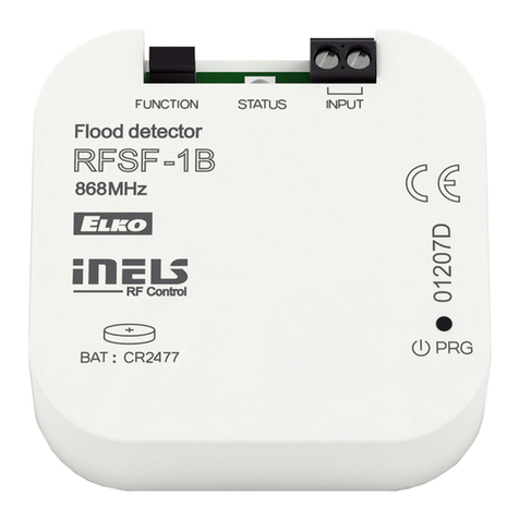
Elko inels RFSF-1B User manual

Elko

Elko inels RFSF-1B User manual

Elko inelsAir AirSF-100L User manual

Elko

Elko inelsAir AirSF-100L User manual

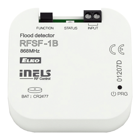
Elko inels RFSF-1B User manual

Elko

Elko inels RFSF-1B User manual

Elko iNELS RFSF-100 Operator's manual

Elko

Elko iNELS RFSF-100 Operator's manual

Elko iNELS RFMD-100 User manual

Elko

Elko iNELS RFMD-100 User manual

Elko inels RFSF-1B User manual

Elko

Elko inels RFSF-1B User manual

Elko iNELS RFSF-100 User manual

Elko

Elko iNELS RFSF-100 User manual

Elko iNELS RFWD-100 User manual

Elko

Elko iNELS RFWD-100 User manual

Elko INELS RFWD-100 User manual

Elko

Elko INELS RFWD-100 User manual

Elko iNELS RFWD-100 User manual

Elko

Elko iNELS RFWD-100 User manual

Elko iNels RFMD-100 User manual

Elko

Elko iNels RFMD-100 User manual

Elko iNELS Air AirKey User manual

Elko

Elko iNELS Air AirKey User manual

Elko iNels RFMD-100 User manual

Elko

Elko iNels RFMD-100 User manual

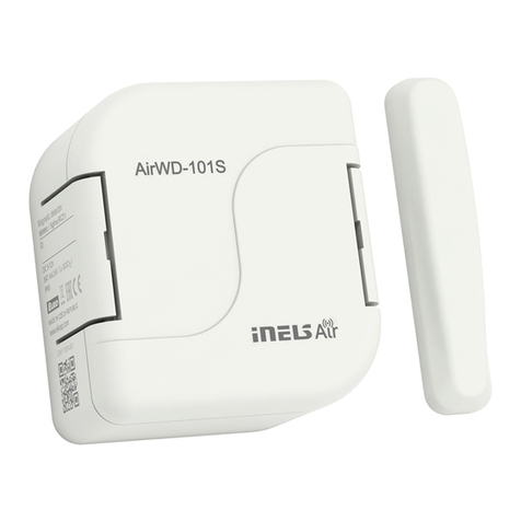
Elko iNels Air AirWD-101 Series User manual

Elko

Elko iNels Air AirWD-101 Series User manual

Elko iNELS Air AirWD-100NB User manual

Elko

Elko iNELS Air AirWD-100NB User manual

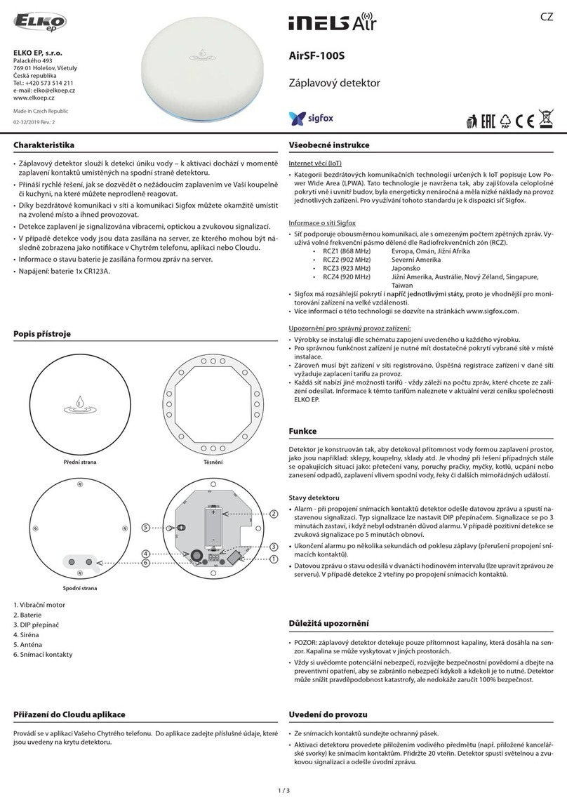
Elko inelsAir AirSF-100S User manual

Elko

Elko inelsAir AirSF-100S User manual

Elko iNELS RFWD-100 User manual

Elko

Elko iNELS RFWD-100 User manual

Elko AirMD-100L User manual

Elko

Elko AirMD-100L User manual

Elko iNels DMD3-1 User manual

Elko

Elko iNels DMD3-1 User manual

Elko ineLS RFSF-100 User manual

Elko

Elko ineLS RFSF-100 User manual

Elko Inels RFSF-18 User manual

Elko

Elko Inels RFSF-18 User manual

Elko inels RFWD-100 User manual

Elko

Elko inels RFWD-100 User manual

Elko iNELS RF Control RFMD-100 User manual

Elko

Elko iNELS RF Control RFMD-100 User manual

Elko iNels Air AirSF-100 User manual

Elko

Elko iNels Air AirSF-100 User manual

Popular Security Sensor manuals by other brands

Reed Instruments R9100 instruction manual

Reed Instruments

Reed Instruments R9100 instruction manual

ORORO HEATED JACKET/HOODIE manual

ORORO

ORORO HEATED JACKET/HOODIE manual

Rielta STEKLO-3 installation guide

Rielta

Rielta STEKLO-3 installation guide

RectorSeal AQUAGUARD 4200E installation instructions

RectorSeal

RectorSeal AQUAGUARD 4200E installation instructions

THORLABS APD440A Operation manual

THORLABS

THORLABS APD440A Operation manual

GDZX ZXSF-1D manual

GDZX

GDZX ZXSF-1D manual

RKI Instruments 65-2494RK Operator's manual

RKI Instruments

RKI Instruments 65-2494RK Operator's manual

ELRO AG40PR11 manual

ELRO

ELRO AG40PR11 manual

System Sensor 4451HT Installation and maintenance  instruction

System Sensor

System Sensor 4451HT Installation and maintenance instruction

Innotech AIO-ENDS-10 instruction manual

Innotech

Innotech AIO-ENDS-10 instruction manual

Philio Technology Corporation PSP05-A manual

Philio Technology Corporation

Philio Technology Corporation PSP05-A manual

GasTech F-GUARD IR3-HD user manual

GasTech

GasTech F-GUARD IR3-HD user manual

Zircon Leak Alert WiFi manual

Zircon

Zircon Leak Alert WiFi manual

System Sensor 5151 Installation and maintenance instructions

System Sensor

System Sensor 5151 Installation and maintenance instructions

Teleco RAIN102H quick start guide

Teleco

Teleco RAIN102H quick start guide

Selcom Security CAYMAN operating manual

Selcom Security

Selcom Security CAYMAN operating manual

Theben compact office 24V installation manual

Theben

Theben compact office 24V installation manual

Gas Clip Technologies Multi Gas Clip Operator's manual

Gas Clip Technologies

Gas Clip Technologies Multi Gas Clip Operator's manual

manuals.online logo
manuals.online logoBrands
  • About & Mission
  • Contact us
  • Privacy Policy
  • Terms and Conditions

Copyright 2025 Manuals.Online. All Rights Reserved.